Nice HySecurity SlideSmart DC Series Assembly instructions

Installation and Programming Manual
SlideSmart™DC
DC10F, DCS10F, DC15, DCS15
Vehicular slide gate operator with Smart DC Controller

(This page intentionally blank)
MX4505 Rev. E ©2020
2 hysecurity.com | 800-321-9947 SlideSmart DC Programming and Operations

TABLE OF CONTENTS
SlideSmart DC
TABLE OF CONTENTS.................................... 4
INTRODUCING SLIDESMART DC ................... 5
Intelligent Features: Smart DC ControllerTM ............................5
Technical Support.......................................................5
Installer's Check List......................................................6
Installer’s Check List ..................................................6
SlideSmart DC Components ......................................... 7
Safety Requirements.....................................................8
INSTALLATION ............................................. 19
Pad Condition...........................................................20
Using an Existing Pad ..............................................21
Front Installation.......................................................22
Rear Installation .......................................................23
Unpacking the Operator ...........................................24
Concrete Pad Mount ................................................25
Gate Bracket and Chain Installation.........................26
Aligning the Chain ....................................................27
Connecting Battery and Turning DC Power On .......28
Programming the Initial Setup Menu........................28
Establishing the Open & Close Limits ......................30
Installing the Target Magnet .....................................31
Installing The Earth Ground .....................................33
POWER ......................................................... 33
Wiring AC Power ...................................................... 34
Wiring 115VAC Power ..............................................35
Wiring 208/230VAC Power....................................... 36
Using A Solar Powered Operator .............................37
Design Requirements & Considerations ..................37
Connecting the SlideSmart DCS to Solar Power .....38
Connecting Peripherals to Solar Operators .............40
Understanding Gate Activity based on Solar Zones. 41
Considerations For DC-Powered Operators ............42
Installing the Extended Battery Backup Kit ..............43
Initial Setup .............................................................. 45
Turning Both Power Switches On ............................ 45
DISPLAY AND MENU OPTIONS .................... 45
Using Smart DC Controller Buttons In Menu Mode .47
Run Mode.................................................................48
Using Smart DC Controller Buttons in RUN Mode...48
Viewing Operator Status Displays............................49
User Menu................................................................50
Adjusting the Close Timer ........................................ 50
Setting the Time and Date........................................ 51
Setting AC Power Loss Gate Function.....................51
Adjusting the Display Contrast ................................. 53
Installer Menu...........................................................57
Resetting the OPEN and CLOSE Limits ..................58
Adjusting Gate Speed ..............................................59
Adjusting the IES Sensitivity ....................................60
Reinstating Factory Defaults .................................... 62
Enabling the Fire Department Override ...................63
SMART DC CONTROLLER ............................ 74
Overview Of The Smart DC Controller.....................75
Vehicle Detector Installation Options .......................78
Connecting Hy5B Vehicle Detectors ........................ 79
Install Standard 11-Pin Box Type Vehicle Detectors 81
Connecting Accessory Devices................................82
Entrapment Sensor Connections ..........................82
Manual Push Button Station.....................................83
User Relays - Programming Procedure ...................84
Power Requirements................................................87
BI-PARTING GATE SYSTEMS ....................... 87
Primary And Secondary Wiring Connections ........... 88
Primary and Secondary Menu Setup .......................89
ACCESSORY CONNECTIONS ....................... 90
Connecting A Radio Receiver For Remote Open.....90
Installing A Maglock Or Solenoid Lock ..................... 90
MX4505 Rev. E ©2020 SlideSmart DC Programming and Operations hysecurity.com | 800-321-9947 3

TABLE OF CONTENTS
Installing a Lock for 12VDC or 24VDC Systems ...... 91
Installing a Lock for High Voltage Systems ..............91
Installing Vehicle Detectors and Loops .................... 92
Monitored External Entrapment Sensors .................95
External Entrapment Protection ...............................97
Photo Eye Installation Tips .......................................97
Photo Eye Function:..............................................98
Edge Sensor Installation Tips................................. 100
Smart DC Controller Troubleshooting .................... 101
Vehicle Detector and Loop Fault Diagnostics ........ 111
SCHEMATICS.............................................. 114
MAINTENANCE........................................... 116
GENERAL MAINTENANCE ................................... 116
Smart Touch Analyze and Retrieve Tool ............. 116
What You Need ................................................... 116
Installing Start Software ...................................... 116
Setting User Account Controls ............................ 117
Electrical Controls .................................................. 117
Mechanical Maintenance ....................................... 117
Software Maintenance ........................................... 117
Drive Belt Tension And Alignment .......................... 118
DC Battery Replacement ....................................... 119
Clock Battery Replacement....................................120
APPENDIX A - INSTALL CONFIGURATIONS 121
APPENDIX B - FRENCH TRANSLATIONS ... 131
PARTS & LIMITED WARRANTY.................. 135
Slidesmart Parts.....................................................135
Slidesmart Parts List ..............................................136
WARRANTY ................................................ 137
SLIDESMART DC SPECIFICATIONS ........... 138
NOTICE
Visit https://hysecurity.com/technical-support/ for installation manuals, replacement part instructions, part
diagrams and more.
MX4505 Rev. E ©2020
4 hysecurity.com | 800-321-9947 SlideSmart DC Programming and Operations

INTRODUCING SLIDESMART DC
Thank you for purchasing our premium SlideSmart DC™ slide gate operator. At HySecurity® Gate, Inc.,
we pride ourselves on quality. Our new line of electromechanical gate operators include a number of
unparalleled user benefits:
Robust - An especially low flex, corrosion resistant, steel chassis combines with an attractive, key-locked,
fade resistant, roto-molded cover. The components on the Smart DC Controller™ are protected by
opto-isolators which shield them from power surges and lightning strikes.
Power - The Smart DC Controller provides variable speed control to a powerful, continuous duty
24V DC motor which drives the gearbox. The electronics, motor and gear box are rated to operate in
temperatures that range from -13°F to 158°F (-25°C to 70°C). SlideSmart DC 15 is rated for gates up
to 40 feet long and 1,500 pounds (12m and 682kg). SlideSmart DC 10F is rate for gates up to 40ft and
1,000lbs. (12m and 454kg). Solar options are available for both models.
Finesse - A variable rate of gate acceleration and deceleration, dependent upon gate weight and length,
assures very smooth handling.
UPS backup and Solar ready - Two 12V, 8 amp hour (Ah) batteries will provide a fully functional gate
operator (up to 4000ft/1219m of gate travel) when AC power is unavailable. Four user-selectable UPS
modes are available. 12VDC and 24VDC are available to power accessory controls. An optional base
extension is available that provides space for the optional 50Ah batteries which support solar applications
or usage during extended power outages.
INTELLIGENT FEATURES: SMART DC CONTROLLERTM
Menus and User relays - The Smart DC Controller has over 55 menu items to allow installer configuration
of gate function and two user relays, which can be configured for over 30 different functions.
Independent adjustment for open and close gate speeds - An easy-to-use menu on the Smart DC
Controller allows the installer to vary the open and close speed settings.
Intelligent Inherent Entrapment Sensor (IES) - Any impediment to gate travel is sensed by the system,
stopping gate movement per UL 325 Safety Standards. The intelligent system monitors gate power then
adapts the IES to trip at an adjustable threshold above normal power.
Improved Liquid Crystal Display (LCD) - A 32-character LCD provides increased readability for
programming and troubleshooting.
USB communications port - A direct connect provides accessibility to download system diagnostics
and upload system configurations using the Smart Touch Analyze and Retrieve Tool (START) software.
START software and diagnostics - With START software loaded on a laptop computer, you can get
the latest software upgrade and have an invaluable troubleshooting tool for all HySecurity operators.
To download this free software, visit the HySecurity website at www.hysecurity.com.
TECHNICAL SUPPORT
For technical support, call your installer or authorized HySecurity distributor. Obtain the serial number
of your operator before calling. Refer to SlideSmart Components on the front page. For the name of a
distributor near you, call HySecurity at 800-321-9947.
For information about HySecurity training for installers, maintenance personnel and end users, refer to
the company website at www.hysecurity.com or call 800-321-9947.
MX4505 Rev. E ©2020 SlideSmart DC Programming and Operations hysecurity.com | 800-321-9947 5

INSTALLER'S CHECK LIST
INSTALLER’S CHECK LIST
The following list provides a high level overview of the tasks involved in installing the SlideSmart DC
gate operator. Take a moment to review the list and check off the items as you complete the install.
Site Prep - concrete pad location/dimensions, distance from gate, chain height, and
mounting considerations: post or base extension, front or rear installation.
Make sure gate installation complies with ASTM F2200 Standard Specification for
Automated Vehicular Gate Construction. And, install the supplied WARNING signs
on both sides of the gate.
Check for compliance with local codes, site conditions, and NEC standards.
Install operator - (on concrete pad use four ½ - 13 x 3.5in long concrete wedge anchors.)
Attach chain end bracket to gate at proper height.
Attach chain to end brackets and feed under SlideSmart idlers and over chain sprocket.
Tighten chain using tensioning bolts.
Verify chain is level with idlers and parallel to operator and gate.
Connect red wire to DC Power Switch.
Turn DC Power ON.
Complete Initial Setup Menu programming.
Install the target magnet and make sure it is in line with and passes by the target sensor
so it can be recognized by the software programming.
Connect AC Power.
Connect all accessory devices.
Set the Close Timer (through the User Menu).
Set gate speed, if applicable (through Installer Menu). Refer to START ("Smart Touch
Analyze and Retrieve Tool" on page 113 in the "Reference" on page 87.
Adjust IES sensitivity, if needed (through Installer Menu).
Check the Smart DC Controller software version. If needed, upload the latest version
from www.hysecurity.com. See "Smart Touch Analyze and Retrieve Tool" on page 113.
Program changes through the Installer Menu depending on the accessory devices
that you have installed.
Give a copy of the operator instructions to the end user. Show the end user how to:
Remove the operator cover. Turn the power off and on to demonstrate learn
limits after DC/AC cycles.
Turn the DC power switch off, which disengages the motor, and manually push
the gate.
Test the red Emergency Stop Button located on the side of the control box. It
can be accessed through a hole in the cover. See illustration on page XXX.
Take photographs of the completed installation site and save it in your business files.
Install external entrapment sensors as needed.
Refer to "Parts & Limited Warranty" on page 132 for SlideSmart parts list.
MX4505 Rev. E ©2020
6 hysecurity.com | 800-321-9947 SlideSmart DC Programming and Operations

SLIDESMART DC COMPONENTS
Service Outlet
115VAC, 15A
O
DC
POW
OF
O
AC
POW
OF
COVER, LATCH
COVER
WARNING
LABEL
PULLEY,
MOTOR
PROTECTION
PLATE
& COVER
PULLEY, GEARBOX
BELT DRIVE, 2 ft/s
PULLEY, GEARBOX
BELT DRIVE, 1 ft/s
GEARBOX
BRUSH
KIT
TRANSFORMER
BATTERY KIT,
8 Ah
SPROCKET
IDLER (x2)
BASE
PLATE
30 ft OF #40 CHAIN,
BRACKET & HARDWARE
BOARD, POWER SUPPLY
TARGET SENSOR (x2)
SERIAL # LOCATION
AC SWITCH,
ON/OFF
115VAC
SERVICE
OUTLET
MOTOR
DC SWITCH,
ON/OFF
SWITCH, RESET
EMERGENCY
STOP BUTTON
BUZZER
CONTROL BOX
BOARD, SMART
DC CONTROLLER
CIRCUIT
BREAKER
MX4505 Rev. E ©2020 SlideSmart DC Programming and Operations hysecurity.com | 800-321-9947 7
SAFETY REQUIREMENTS
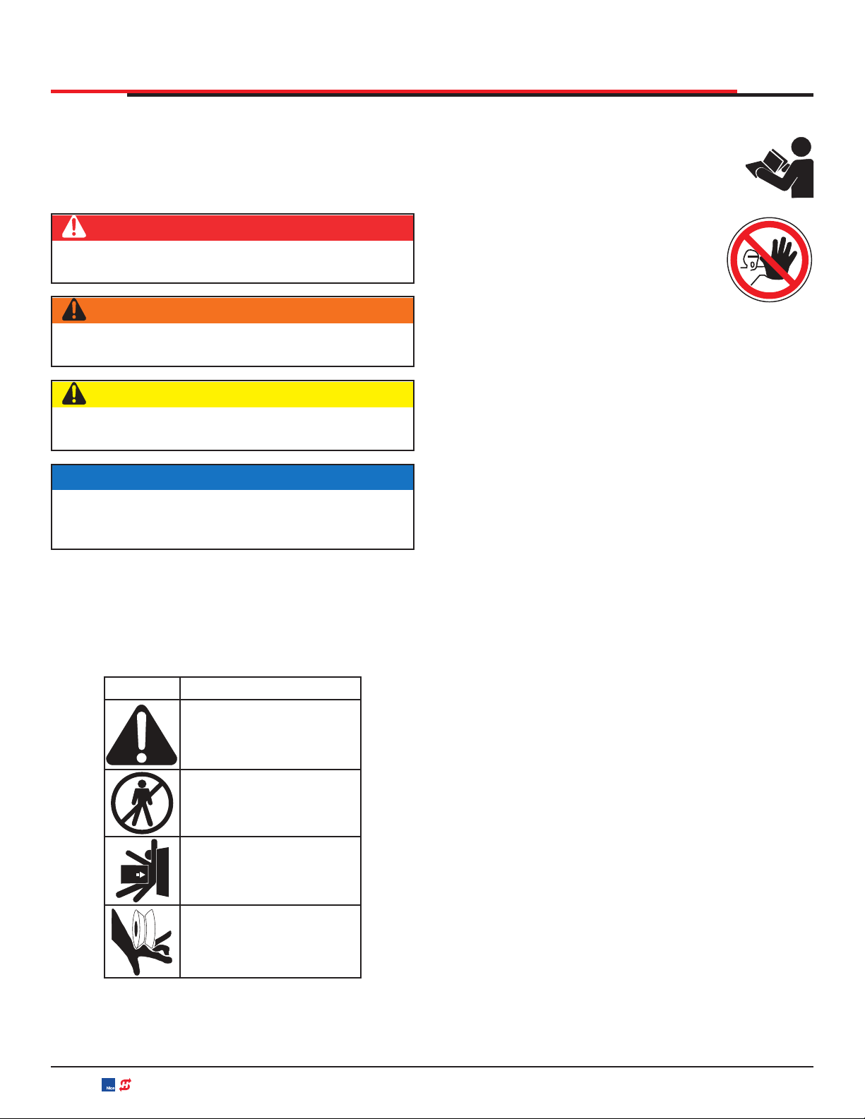
SAFETY MESSAGES
The safety messages below inform you about potential
hazards that can result in injury. Safety messages specifically
address level of exposure to operator and are preceded by
one of four words: DANGER, WARNING, CAUTION or
NOTICE.
COMMON INDUSTRIAL SYMBOLS
These international safety symbols may appear on product
or in its literature to alert of potential personal injury hazards.
Obey all safety messages that follow these symbols to avoid
possible injury or death.
Symbol Safety Hazard
Attention -
Take Notice
Danger -
Keep Away
Entrapment Zone
Possible Pinch Point
DANGER
Indicates a hazardous situation which, if not avoided,
WILL result in DEATH or SERIOUS INJURY.
WARNING
Indicates a hazardous situation which, if not avoided,
COULD result in DEATH or SERIOUS INJURY.
CAUTION
Indicates a hazardous situation which, if not avoided,
COULD result in MINOR or MODERATE INJURY.
NOTICE
Addresses practices not related to personal injury.
Indicates damage to equipment is probable if the
hazardous situation is not avoided.
IMPORTANT SAFETY INSTRUCTIONS
Hazards, associated with automatic gates, can
be reduced with proper site design, installation,
and use. Installers, maintenance crews, and
owners/users must read and follow the safety
requirements found in HySecurity® product
manuals.
It is important that only qualified installers
handle installation of HySecurity Gate
vehicular gate operators. A “qualified”
installer has one of the following:
1. A minimum of three years experience installing simila
r
equipment.
2. Proof of attending a HySecurity Technical Training
seminar within the past three years.
3. Significant manufacturer endorsements of technical
aptitude in gate operator installation and operation.
Underwriter Laboratories (UL) and the American Society fo
r
Testing and Materials (ASTM) are responsible for current
safety standards and regulations regarding gate operators
and automated gates. All aspects of gate installation must
comply with the appropriate safety standard. For the most
up-to-date ASTM F2200 Gate and Fence Standards, refe
r
to www.astm.org. For UL 325 Safety Standard, refer to
www.ul.com. Consult local government agencies for up-to-
date rules and regulations as certain municipalities have
established licensing, codes or regulations that regulate
automated gate system design and installation.
GENERAL SAFETY INFORMATION
A gate operator is only a component in a gate system.
The other parts of the gate system can include the
gate, the external safety sensors, access controls, and
vehicle detectors. To have a gate system that provides
for safety, security, and reliable operation it is essential
these components operate together as a system. It is
the responsibility of the system designer and/or installe
r
to ensure any safety or operational issues have been
addressed.
MX4505 Rev. E ©2020
8 hysecurity.com | 800-321-9947 SlideSmart DC Programming and Operations
SAFETY REQUIREMENTS
WARNING
To reduce the risk of injury or death:
1. READ AND FOLLOW ALL INSTRUCTIONS.
2. Never let children operate or play with gate controls. Keep the remote control away from children.
3. Always keep people and objects away from the gate. NO ONE SHOULD CROSS THE PATH OF THE MOVING
GATE.
4. Test the gate operator monthly. The gate MUST reverse on contact with a rigid object or stop when an object
activates the non-contact sensors. After adjusting the force or the limit of travel, retest the gate operator. Failure to
adjust and retest the gate operator properly can increase the risk of injury or death.
5. Use the emergency release only when the gate is not moving.
6. KEEP GATES PROPERLY MAINTAINED. Read the user’s manual. Have a qualified service person make repairs to
gate hardware.
7. The entrance is for vehicles only. Pedestrians must use separate entrance.
8. SAVE THESE INSTRUCTIONS.
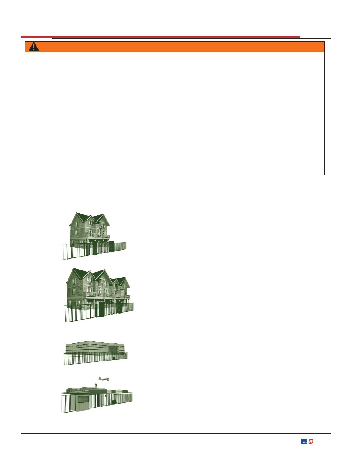
IDENTIFYING GATE OPERATOR CATEGORY AND UL 325 USAGE CLASS
The UL 325 standard covers gate operators. Within this safety standard several Usage Classes are described that defin
e
different types of installations where gate operators can be applied. Some operators are restricted in their usage application
.
Appropriate Usage Classes are shown in the Specifications.
Class I Class I: Intended for use in a location of one to four single family dwellings
or a parking area associated with one to four single family dwellings.
Class II
Class II: Intended for use in a commercial location or building such as a multi-
family housing units (five or more single family units) hotels, garages, retail
stores or other buildings servicing general public.
Class III Class III: Intended for use in an industrial location or building such as factories
or loading docks or other locations not accessible by the general public.
Class IV
Class IV: Intended for use in guarded industrial locations or buildings such as
an airport security area or other restricted access location, not servicing general
public, in which access is monitored by security personnel or via closed circuitry.
MX4505 Rev. E ©2020 SlideSmart DC Programming and Operations hysecurity.com | 800-321-9947 9

SAFETY REQUIREMENTS
VEHICULAR TRAFFIC ONLY
WARNING
This automatic gate operator is not designed nor is it intended for pedestrian traffic. Vehicular gate operators must by
their nature be powerful to function reliably. This power can cause injury or death. Accordingly, direct all pedestrian traffic
to a separate walk-through gate.
Install this gate operator only when:
The operator is appropriate for the construction of the
gate and the usage Class of the gate.
All openings of a horizontal slide gate are guarded or
screened from the bottom of the gate to a minimum of
1.83 m (6 ft) above the ground to prevent a 57.2 mm (2-1/4
in) diameter sphere from passing through the openings
anywhere in the gate, and in that portion of the adjacent
fence that the gate covers in the open position.
All exposed pinch points are eliminated or guarded.
Guarding is supplied for exposed rollers.
The operator is intended for installation only on gates used for
vehicles. Pedestrians must be supplied with a separate access
opening. The pedestrian access opening shall be designed to
promote pedestrian usage. Locate the gate such that persons
will not come in contact with the vehicular gate during the entire
path of travel of the vehicular gate.
The gate must be installed in a location so that enough
clearance is supplied between the gate and adjacent structures
when opening and closing to reduce the risk of entrapment.
Swinging gates shall not open into public access areas.
The gate must be properly installed and work freely in both
directions prior to the installation of the gate operator. Do
not over-tighten the operator clutch or pressure relief valve
to compensate for an improperly installed, improperly
functioning, or damaged gate.
Permanently mounted controls intended for user activation
must be located at least 1.83 m (6 ft) away from any moving
part of the gate and where the user is prevented from
reaching over, under, around or through the gate to operate
the controls.
Exception: Emergency access controls only accessible
by authorized personnel (e.g. fire, police, EMS) may be
placed at any location in the line-of-sight of the gate.
The Stop and/or Reset button must be located in the line-
of-sight of the gate. Activation of the reset control shall not
cause the operator to start.
A
minimum of two (2) WARNING SIGNS shall be installed,
in the area of the gate. Each placard is to be visible by
persons located on the side of the gate on which the placard
is installed.
For gate operators utilizing a non-contact sensor (Photo
Eye):
See instructions on the placement of non-contact
sensors for each type of application.
Care shall be exercised to reduce the risk of nuisance
tripping, such as when a vehicle trips the sensor while
the gate is still moving.
One or more non-contact sensors shall be located where
the risk of entrapment or obstruction exists, such as the
perimeter reachable by a moving gate or barrier.
For a gate operator utilizing a contact sensor (Edge):
One or more contact sensors shall be located where
the risk of entrapment or obstruction exists, such as at
the leading edge, trailing edge, and postmounted both
inside and outside of a vehicular horizontal slide gate.
A hardwired contact sensor shall be located and its
wiring arranged so that the communication between
the sensor and the gate operator is not subjected to
mechanical damage.
A wireless device such as one that transmits radio
frequency (RF) signals to the gate operator fo
r
entrapment protection functions shall be located where
the transmission of the signals are not obstructed o
r
impeded by building structures, natural landscaping
or similar obstruction. A wireless device shall function
under the intended end-use conditions.
One or more contact sensors shall be located on
the inside and outside leading edge of a swing gate.
Additionally, if the bottom edge of a swing gate is greate
r
than 152 mm (6 in) but less than 406 mm (16 in) above
the ground at any point in its arc of travel, one or more
contact sensors shall be located on the bottom edge.
USE OF VEHICLE DETECTORS
Use of vehicle detectors (loop detectors) is strongly
encouraged to prevent damage to vehicles caused by gates
closing on them. This is not considered to be a safety item as
vehicle detectors cannot provide protection to pedestrians.
In some situations, photoelectric devices may be used as
vehicle detectors, but should be wired accordingly.
GATE CONSTRUCTION AND SAFETY
Gate construction plays a very important role in ensuring
the safety of any automated gate system. The standard fo
r
gate construction is ASTM F2200. Below are key areas to
address in gate design for safety. For complete information
consult the standard. Copies of the standard are available at:
https://www.astm.org/Standards/F2200.htm.
MX4505 Rev. E ©2020
10 hysecurity.com | 800-321-9947 SlideSmart DC Programming and Operations

SAFETY REQUIREMENTS
A
nother source of information is available from DASMA, the
Door and Access System Manufacturer’s Association. The
A
ssociation publishes Technical Data Sheets, one of which
concerns ASTM F2200. For more information, see:
http://www.dasma.com/PDF/Publications/TechDataSheets/
OperatorElectronics/TDS370.pdf.
General Requirements for gate construction:
Gates shall be constructed in accordance with the
provisions given for the appropriate gate type listed.
Refer to ASTM F2200 for additional gate types.
Gates shall be designed, constructed and installed to not fall
over more than 45 degrees from the vertical plane, when a
gate is detached from the supporting hardware.
Gates shall have smooth bottom edges, with vertical bottom
edged protrusions not exceeding 0.50 in (12.7 mm) other
than the Exceptions listed ASTM F2200.
The minimum height for barbed wire shall not be less than 6
ft (1.83 m) above grade. The minimum height for barbed tape
shall not be less than 8 ft (2.44 m) above grade.
An existing gate latch shall be disabled when a manually
operated gate is retrofitted with a powered gate operator.
A gate latch shall not be installed on an automatically
operated gate.
Protrusions shall not be permitted on any gate. Consult
ASTM F2200 for exceptions.
Gates shall be designed, constructed and installed such
that their movement shall not be initiated by gravity when
an automatic operator is disconnected.
For pedestrian access in the vicinity of an automated
vehicular gate, a separate pedestrian gate shall be
provided. The pedestrian gate shall be installed in a
location such that a pedestrian shall not come in contact
with a moving vehicular access gate. A pedestrian gate
shall not be incorporated into an automated vehicular
gate panel.
Any non-automated gate that is to be automated shall be
upgraded to conform to the provisions of this specification.
This specification shall not apply to gates generally
used for pedestrian access and to vehicular gates not
to be automated.
Any existing automated gate, when the operator requires
replacement, shall be upgraded to conform to the
provisions of this specification in effect at that time.
The following provisions shall apply to Class I, Class II,
Class III, and Class IV vehicular horizontal slide gates:
All weight bearing exposed rollers 8 ft (2.44 m), or less, above
grade shall be guarded or covered.
All openings shall be designed, guarded, or screened from
the bottom of the gate to the top of the gate or a minimum o
f
72 inch (1.83 m) above grade, whichever is less, to prevent
a 2-1/4 inch (57 mm) diameter sphere from passing through
the openings anywhere in the gate, and in that portion o
f
the adjacent fence that the gate covers in the open position.
The gate panel shall include the entire section of the moving
gate, including any back frame or counterbalance portion o
f
the gate.
A gap, measured in the horizontal plane parallel to the
roadway, between a fixed stationary object nearest the
roadway (such as a gate support post) and the gate frame
when the gate is in either the fully open position or the fully
closed position, shall not exceed 2-1/4 inches (57 mm).
Exception: All other fixed stationary objects greater than 16
inches (406 mm) from the gate frame shall not be required
to comply with this section.
Positive stops shall be required to limit travel to the designed
fully open and fully closed positions. These stops shall be
installed at either the top of the gate, or at the bottom of the
gate where such stops shall horizontally or vertically project
no more than is required to perform their intended function.
All gates shall be designed with sufficient lateral stability to
assure that the gate will enter a receiver guide. Consult ASTM
F2200 for details on various gate panel types.
SECONDARY ENTRAPMENT PROTECTION
SENSORS
Most HySecurity gate operators are equipped with a Type
A, Inherent Entrapment Sensor (IES). UL 325 Safety Standard
compliance requires installation of external entrapment
protection sensors, the number of which, depends on
entrapment hazards that exist at each particular installation.
To comply with UL 325, the following external sensors may
be used:
Contact sensors, such as edge sensors
Non-contact sensors, such as photo eyes
Site designer or installer can choose either photo eyes,
edge sensors, or a combination of these devices. Whatever
devices are used, protection in both opening and closing
directions of gate travel must be provided.
UL 325 Safety Standard for automatic sliding gates
specifically requires that edge sensors, photo eyes, or a
combination of both devices be installed to protect against
pedestrian entrapment in BOTH directions of gate travel
and wherever entrapment hazards exist.
MX4505 Rev. E ©2020 SlideSmart DC Programming and Operations hysecurity.com | 800-321-9947 11

SAFETY REQUIREMENTS
PHOTO EYES: One or more non-contact sensor
(photo eyes) shall be located where entrapment risk
or obstruction exists, such as perimeter reachable by a
moving gate.
Care shall be exercised to reduce the risk of nuisance
tripping, such as when a vehicle trips the sensor while the
gate is moving.
EDGE SENSORS: One or more contact sensors (edge
sensors) shall be located at leading edge, trailing edge,
and post-mounted, both inside and outside of a sliding
gate.
One or more contact sensors shall be located on the inside
and outside leading edge of a swing gate. Additionally, if
the bottom edge of a swing gate is greater than 6"(152mm)
but less than 16"(406mm) above the ground at any point in
its arc of travel, one or more contact sensors shall be located
on the bottom edge.
SENSOR SECURITY: A hard-wired contact sensor shall
CAUTION
A contact or non-contact sensor is also required to
protect against possible entrapment if gate opens to
a position less than 16 inches from any object, such as
a post or wall.
be located and its wiring arranged so that communication
between sensor and gate is not subjected to mechanical
damage.
SENSOR FUNCTION and COMMUNICATION: A sensor
that transmits its signal to gate operator must be located
so its signal is not impeded by building structures or other
obstructions. All sensors must be installed so that they
function as intended for end-use conditions.
UL 325 LISTING: Edge sensors and photo eyes must
be tested and labeled as “Recognized Components” or
otherwise certified to UL 325 requirements in order to
be deemed acceptable for use in a gate operator. Study
Important Safety Instructions and consider your specific
installation to determine where greatest entrapment
risks exist. Locate edge sensors and/or photo sensors
accordingly. Be certain that a sufficient number of sensors
are used so that pedestrians are protected from entrapment
in both directions of gate travel and all hazard areas are
fully protected. Most HySecurity gate operators require
external entrapment sensors that utilize Normally Closed
(NC) contact means of monitoring. HySecurity gate
operators utilizing the SmartCNX Controller require external
entrapment sensors that have a 10k Ohm or 4-wire pulsed
monitoring scheme. Refer to UL website at www.ul.com for
most up-to-date list of gate operator safety standards (UL
325). Refer to www.astm.org for a complete list of ASTM
F2200 Gate and Fence Standards.
Gate operator will not automatically cycle the gate unless an indication that the appropriate
number of external entrapment protection sensors are connected and operational.
The normally closed (NC) entrapment protection sensors wired to the Controller’s SENSOR
inputs are monitored using HySecurity software. Prompts appear on the display requesting
specific configurations based on the gate operator type.
Use of Approved External Entrapment
Protection Sensors is REQUIRED
325
Effective August 1st, 2018, the UL 325 Standard has changed:
• The operator shall monitor for the presence of every device at least once during each open and close cycle (32.1.8)
• It shall not be possible to make simple modifications in the field by adding, suppressing or changing, either on the operator or
external entrapment protection device(s), to bypass, interfere with, or otherwise defeat the monitoring function. (32.1.10)
• Entrapment zones are now defined for each gate type (4.23, 4.24, 4.29, 4.34)
SLIDE GATES: To enable fully automatic operation, all SLIDE gate operators will require a minimum of TWO monitored external
entrapment protection sensors (one for each direction) to protect entrapment zones in both the open and close direction of travel.
Preferred solution for slide gates: A photo eye for the close direction and a hard-wired edge sensor for the open direction
that is mounted to the face of the leading post of the fence behind the gate. (Reach through injuries are the most common
hazard associated with automatic sliding gates)
SWING GATES: To enable fully automatic operation, all SWING gate operators will require a minimum of ONE monitored external
entrapment protection sensor to protect entrapment zones in either the open or close direction of travel. However, an additional
monitored sensor is required if there is a risk of entrapment in both directions of gate travel.
Preferred solution for swing gates: A photo eye for the close direction and/or a hard-wired wraparound edge sensor on the
leading edge of the gate, which protects for both directions of gate travel.
MX4505 Rev. E ©2020
12 hysecurity.com | 800-321-9947 SlideSmart DC Programming and Operations
SAFETY REQUIREMENTS
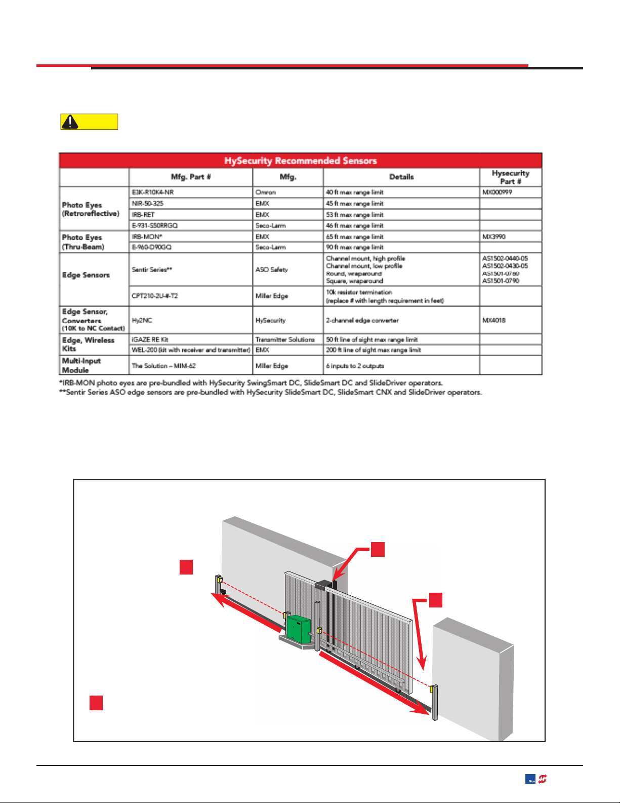
T
h
e
f
o
ll
owing sensors
h
ave
b
een teste
d
wit
h
HySecurity gate operators
b
y an in
d
epen
d
ent
l
a
b
oratory an
d
certi
fi
e
d
to
comply with UL 325 7th Edition. Select sensors from this list for UL compliant gate automation solutions. Contact the
sensor manufacturer for specific recommendations for use.
CAUTION All external entrapment protection sensors must have NC sensor outputs and be wired to the SENSOR COM
terminal for monitoring and powering purposes. Depending on software version, the sensor becomes powered
when the gate operator’s motor runs or is always powered when the operator is connected to AC power.
Installers must assess each specic site and
install sensors that protect all potential entrapment zones.
For more information visit Gate Safety at www.hysecurity.com/gatesafety or
see latest operator manual at www.hysecurity.com/contact-us/technical-support/installation-manuals
Protects open direction
(EDGE OPEN)
1
A
Install Edge for
Draw-in Zone
Trailing End
Leading End
PUBLIC
SECURE
2
Install Photo eye
Protects Leading End
(EYE CLOSE)
Slide Gate
Common
Entrapment
Zones
Indicates Additional Potential Entrapment Zone
A
MX4505 Rev. E ©2020 SlideSmart DC Programming and Operations hysecurity.com | 800-321-9947 13

SAFETY REQUIREMENTS
ELECTRICAL SAFETY
Turn gate operator and all circuit
breakers OFF before performing
maintenance on the gate operator
or making contact with output
receptacles.
Never insert any objects into output
receptacles during operation. The
possibility exists of electrical shock,
electrocution, or death.
Never let power wires lay in water.
Never use damaged or worn wire when connecting
equipment. Inspect for cuts in the insulation.
Never grab or touch a live power
cord or cable with wet hands. The
possibility exists of electrical shock,
electrocution or death.
Always make certain that proper
power has been selected for the job.
See Cable Selection Chart in this
manual.
GROUNDING SAFETY
Always make sure that electrical
circuits are properly grounded to a
suitable earth ground (ground rod)
per the National Electrical Code
(NEC) and local codes. Severe
injury or death by electrocution
can result from operating an
ungrounded operator.
Never use gas piping as an electrical ground.
BATTERY SAFETY
HySecurity operators use sealed Absorbed Glass Mat (AGM)
batteries and HySecurity highly recommends replacing used
batteries with new AGM-type batteries.
CAUTION
Batteries used with HySecurity gate operator contain
materials considered hazardous to environment.
Proper battery disposal is required by federal law.
Refer to Hazardous Waste Regulations federal
guidelines.
To reduce risk o
f
fi
re or injury to persons:
Observe polarity between batteries and charging circuit.
Never mix battery sizes, types, or brands. Charging circuit
on HySecurity DC operators is designed for AGM-type
batteries, not flooded lead acid-type batteries.
Exercise care in handling batteries. Be
aware metal found in rings, bracelets, and
keys can conduct electricity, short
batteries, and cause potential injury.
Do not open or mutilate batteries. Battery cells
contain corrosive materials which may cause
burns and other injuries. Material within
batteries is toxic.
Always dispose of batteries properly. Do not
place batteries in fire. Battery cells may
explode. Follow federal guidelines for proper
disposal of hazardous waste.
Always keep battery cables in good working
condition. Repair or replace all worn cables.
Replace batteries according to instructions
found in DC Battery Replacement.
Do not charge frozen battery. Battery can
explode. If frozen, warm the battery to at
least 61°F (16°C).
ENVIRONMENTAL SAFETY/
HAZARDOUS MATERIALS AND PROPER
DISPOSAL
Decommissioning is a controlled process used to safely
retire a piece of equipment that is no longer
serviceable. If the equipment poses an
unacceptable and unrepairable safety risk due to
wear or damage or is no longer cost effective to
maintain (beyond life-cycle reliability) and is to be
decommissioned (demolition and dismantlement), be sure to
follow rules below.
Do not pour waste or oil directly onto the ground, down a
drain or into any water source.
Contact your country's Department of Public Works o
r
recycling agency in your area and arrange for prope
r
disposal of any electrical components, waste or oil
associated with this equipment.
When the life cycle of this equipment is over, remove battery
and bring to appropriate facility for lead reclamation. Use
safety precautions when handling batteries that contain
sulfuric acid.
When the life cycle of this equipment is over, it is
recommended that the frame and all other metal and plastic
parts be sent to a recycling center.
Metal and plastic recycling involves the collection of metal and
plastic from discarded products and its transformation into raw
materials to use in manufacturing a new product.
MX4505 Rev. E ©2020
14 hysecurity.com | 800-321-9947 SlideSmart DC Programming and Operations

SAFETY REQUIREMENTS
Recyclers and manufacturers alike promote the process
of recycling metal and plastic. Using a metal and plastic
recycling center promotes energy cost savings.
WIND LOAD FACTORS & SITE PREP
Wind load is always a factor when
considering the appropriate gate for a
particular site. Solid gate panels produce
a larger wind load than gates with slats
or open decorative features. If you are
installing a gate operator in a high wind
area, gate design will affect the load on
the gate operator because wind load acts
the same as an obstruction. Good gate
panel design presents a low surface area
to reduce the wind load.
If gate is heavy and near weight capacity of what the gate
operator can handle (see specifications), make sure it has
an open design that allows wind to flow through it. A solid or
semi-solid gate design under certain wind load conditions
may cause damage to gate operator and is not covered by
the HySecurity Limited Warranty.
Several factors play into calculations of wind load on a gate
panel. To find out maximum wind speed in areas around
the United States, search for US government wind speed
maps on the internet. If you don’t know how to calculate for
wind load, ask a mechanical engineer or site architect for
assistance prior to installing gate operator and gate panels.
When the IES trips, it sends a signal to gate operator to stop
and reverse direction. This feature may be falsely triggered
in excessively windy conditions because wind itself, acting
over surface area of gate panel, can provide necessary
force to trigger IES.
CAUTION
Do not adjust IES sensitivity to accommodate for
inappropriately designed gate panels. Loss of IES
sensitivity increases mechanical wear on gate
hardware and gate operator. It may also pose a safety
hazard. Compensating for wind loads by adjusting
IES may set IES sensitivity to a level which, when
encountering an obstruction, ignores obstruction and
fails to reverse direction. For more information, refer to
Adjusting the IES Sensitivity.
MAINTENANCE
OF
GATE
SYSTEMS
To keep your automated gate system performing both safely
and reliably it is important to ensure that the components o
f
that system are functioning properly.
At least monthly:
Disconnect the gate operator and manually move the
gate through its range of travel. Note any squeaks from
rollers or hinges or areas of binding. The gate should
travel smoothly and quietly throughout its range. If it
does not, contact a gate professional to correct the
problem.
Reconnect the gate operator and perform the following
tests:
• With the gate opening, block any photo eyes and/
or depress any safety edges used to protect the
open direction. The gate should stop and/or reverse.
• With the gate closing, block any photo eyes and/o
r
depress any safety edges used to protect the close
direction. The gate should stop and/or reverse.
• Using a suitable obstruction in the path of the gate
(a solid, immovable object), run the gate in the open
direction until it contacts the obstruction. The gate
should stop and reverse.
• Using a suitable obstruction in the path of the gate
(a solid, immovable object), run the gate in the close
direction until it contacts the obstruction. The gate
should stop and reverse.
MX4505 Rev. E ©2020 SlideSmart DC Programming and Operations hysecurity.com | 800-321-9947 15
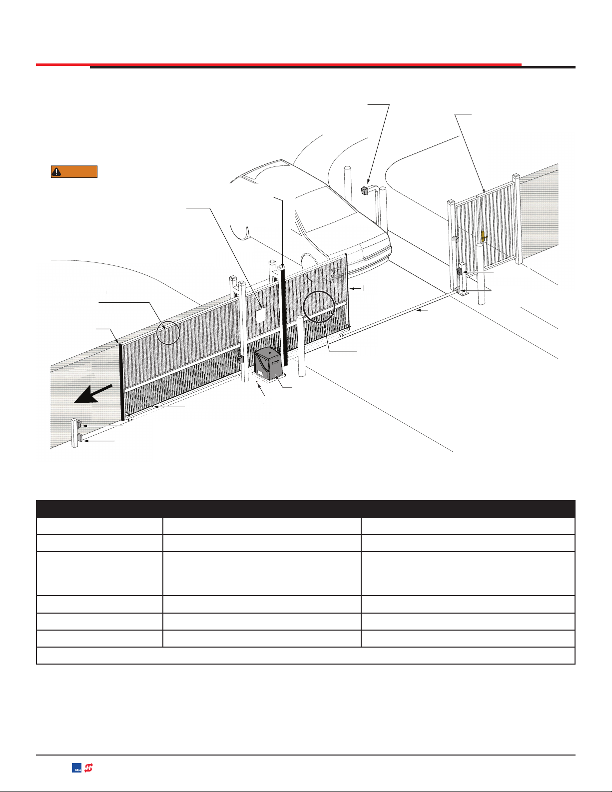
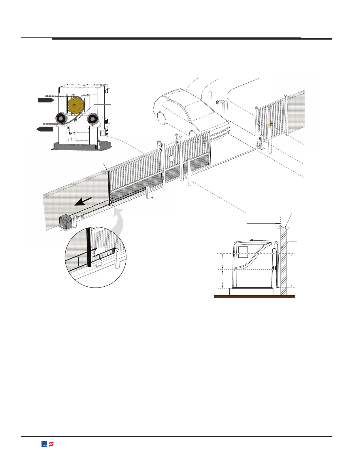
INSTALLATION
Site Overview & Planning
Figure 1. Site Overview and Planning
Table 1. SlideSmart Specifications
Operator SlideSmart DC 15 SlideSmart DC 10F
Duty Cycle Continuous Continuous
Power, 1Ø
Switch Selectable
115 volts, 3 amps, 50/60 Hertz
208-230 volts, 1.5 amps, 50/60 Hertz
Switch Selectable
115 volts, 3 amps, 50/60 Hertz
208-230 volts, 1.5 amps, 50/60 Hertz
Motor ½ hp ½ hp
Gate Speed 0.75, 1 ft/s (23, 30, 38 m/s) 1.75, 2 , or 2.25 ft/s (53, 61, or, 69 cm/s)
Gate Weight Maximum 1500 lbs (675 kg) Maximum 1000 lbs (450 kg)
Note: For SlideSmart DC Solar operators, refer to www.hysecurity.com
Secure Side
Public Side
Attach WARNING Signs
Be sure to place the
WARNING signs on both
sides of the gate. For your records, take a
ƉŚŽƚŽŐƌĂƉŚŽĨƚŚĞĐŽŵƉůĞƚĞĚŝŶƐƚĂůůĂƟŽŶƐŝƚĞ
WARNING
Maximum 2¼" (57mm)
width between
ǀĞƌƟĐĂůďĂƌƐ
>ĞŌ,ĂŶĚ'ĂƚĞ
opening
Physical stop - weld stops at both ends of V track
WŚŽƚŽĞLJĞ;ĞŶƚƌĂƉŵĞŶƚƉƌŽƚĞĐƟŽŶƐŚŽǁŶŝŶĨŽƵƌůŽĐĂƟŽŶƐͿ
Pedestrian gate.
Key or Card reader
Mount access control
ĚĞǀŝĐĞƐĂƚůĞĂƐƚϲŌ
(183cm) beyond the gate.
Make sure a separate walk-
through entrance is available
and its pedestrian path is
clearly designated.
Target magnet on chain
SlideSmart
To comply with ASTM F2200, a screened wire
mesh extends to the top of the gate or to a mimimum
ŚĞŝŐŚƚŽĨϲŌ;ϭϴϯĐŵͿŝĨĂϮЬΗ;ϱϳŵŵͿŽƌůĂƌŐĞƌŐĂƉĞdžŝƐƚƐ
ďĞƚǁĞĞŶƚŚĞǀĞƌƟĐĂůďĂƌƐ
Site Overview
Edge sensor on
leading edge
V track
Physical
stop
Earth ground
Photo eye
2¼"
(
57mm
)
ween
ƌƐ
ŶĚ'ĂƚĞ
g
Target magnet on chain
h
T
o co
m
Edge
l
ead
Edge sensor
on trailing
edge
Edge sensor
MX4505 Rev. E ©2020
16 hysecurity.com | 800-321-9947 SlideSmart DC Programming and Operations

PAD CONDITION
1. Follow the local building codes to identify the
frost line and determine the required depth of
the concrete pad. HySecurity recommends a
minimum 16-inch depth with a minimum 2-inch
extension Refer to Figure 2.
2. Before pouring the pad, consider conduit
placement so it fits within the confines of the
6.9 x 12-inch cutout in the SlideSmart as shown
in Figure 2. Run separate conduits for:
high voltage wiring (115/230V supply power)
including equipment ground
INSTALLATION
Low voltage wiring (12V and 24V accessory
power)
• vehicle loop control wiring
• primary/secondary connections
Earth ground (NEC/NFPA)
3. Extend conduit height 2-inches (5cm) above
the pad (4-inches (9cm) above ground level).
Make sure the concrete forms are square with
the gate and the pad is level. The operator
footprint, with covers, is approximately an
18-inch square (4.7cm). See Figure 2 for the
minimum pad dimensions.
Figure 2. Conduit View
Grounding rod depth at
10(3m) or per local code
Vehicle loop
control wires
Extra conduit
(Dual Gate wiring)
(Conduit may be shared with low voltage wires)
Low
voltage/Communicaon wires
20.7"
(52.6cm)
Conduit runs
2" (5cm) above
concrete pad
Minimum pad
height is 2" (5cm)
above grade level.
High voltage wires
Main AC power
Cut-away
view
Concrete pad
(depth set per
local codes)
Consult local
codes for
proper depth
3 max.
(91.4cm)
Ground
lug
Chain
SlideSmart HD
operator
Grade level
Ground
wire & rod
19" minimum
(48.3cm)
Area
cut out
for
conduit
6.9 x 12"
(17.5 x 30.5cm)
GateChain,
#40 Roller
Sloed holes (4x) for
concrete anchors:
½ - 13 x 3½"
21"
(53.3cm)
10.5"
(26.7cm)
1.6"
(4.1cm)
6.4"
(16.3cm)
10.4"
(26.4cm)
Concrete
pad
MX4505 Rev. E ©2020 SlideSmart DC Programming and Operations hysecurity.com | 800-321-9947 17

USING AN EXISTING PAD
In many applications, SlideSmart may be a
replacement operator for an existing gate system.
Make sure the pad is level and inspect the pad for:
Compliance with local building codes.
Appropriate distance from the gate. See Figure
3.
Appropriate dimensions (See Figure 3) for
SlideSmart installation.
Durability.
INSTALLATION
To use an existing pad, take the following steps:
1. Remove any existing equipment from the pad.
2. Measure the pad to ensure it is sized properly
for SlideSmart.
3. Check the mounting hole locations and re-drill,
if necessary.
4. Follow the steps in "Concrete Pad Mount" on
page 22.
CAUTION
Consider positioning the operator so existing
conduit enters the cutout in the SlideSmart
base plate. Cutting small holes in the plastic
base plate and cover for pre-existing conduit
is permissible. Two 0.875-inch (22mm) diameter
holes for running conduit are also provided on
both sides of the chassis. See Figure 4.
Figure 3. Conduit Side View
Side View
7¾"
(19.7cm)
Gate
Chain to Gate
Ideal distance = 3-1/4" (8.25cm)
Min. distance = 2-1/2" (6.4cm)
Chain
height
Grade
level
Concrete pad
Cut out
if rear
install
Conduit cut outs
Figure 4. Conduit Cut Out Views
MX4505 Rev. E ©2020
18 hysecurity.com | 800-321-9947 SlideSmart DC Programming and Operations

FRONT INSTALLATION
The most common and cost efficient type of installation is the front installation. See Figure 5 and Figure 6.
Figure 5. Front Installation
Figure 6. Base Extension Mount
Secure Side
Public Side
P
ublic
S
id
e
Chain bracket (x2)
Chain
Physical Stop (x2)
NOTICE
Several different ways to mount the SlideSmart operator exists. A few are shown here. For more
detailed drawings, refer to the "Appendix A - Installation Configurations" on page 118.
OPTIONAL
50Ah
batteries
BASE EXTENSION
MOUNT
POST MOUNTED POST MOUNTED WITH
BASE EXTENSION
CHAIN
INSTALLATION
MX4505 Rev. E ©2020 SlideSmart DC Programming and Operations hysecurity.com | 800-321-9947 19
REAR INSTALLATION
A rear installation requires additional idler wheels and gate brackets, but it provides aesthetics as the
chain is not visible along the gate. See Figure 7.
Figure 7. Rear Installation
>ĞŌ,ĂŶĚ'ĂƚĞ
ŽƉĞŶŝŶŐ
8"
5"
/ĚůĞƌWŽƐƚ
WŽƐŝƟŽŶƉŽƐƚƚŽŵĂŝŶƚĂŝŶĂŵŝŶŝŵƵŵ
ĚŝƐƚĂŶĐĞŽĨϭĨŽŽƚ;ϯϭĐŵͿĨƌŽŵƚŚĞĞŶĚ
ŽĨƚŚĞŐĂƚĞǁŚĞŶŐĂƚĞŝƐĨƵůůLJĐůŽƐĞĚ
ŶĚŽĨƚŚĞŐĂƚĞ
ŚĂŝŶΘďƌĂĐŬĞƚƉŽƐŝƟŽŶ
ϴ;ϮϬĐŵͿĂŶĚϱ;ϭϯĐŵͿ
'ĂƚĞ
Side View
ŽŶĐƌĞƚĞƉĂĚ
Chain to Gate
/ĚĞĂůĚŝƐƚĂŶĐĞсϯвΗ;ϵϱĐŵͿ
DŝŶĚŝƐƚĂŶĐĞсϮЪΗ;ϲϰĐŵͿ
7вΗ
;ϭϵϳĐŵͿ
8"
;ϮϬϯĐŵͿ
ŚĂŝŶ
ŚĞŝŐŚƚ
>ĞŶŐƚŚĞŶƚŚĞ
ĐŚĂŝŶĂĐĐĞƐƐƐůŽƚďLJ
ĐƵƫŶŐƚŚĞĐŽǀĞƌŽŶ
ƚŚĞĐŚĂŝŶƐŝĚĞŽŶůLJ
ϭϳЪΗ
;ϰϰϱĐŵͿ
^WZK<d
,/E
/>Zt,>
dZ'd
D'Ed
dĂƌŐĞƚŵĂŐŶĞƚƉŽƐŝƟŽŶ
ďĞƚǁĞĞŶŝĚůĞƌǁŚĞĞůĂŶĚ
ƐƉƌŽĐŬĞƚǁŚĞŶŐĂƚĞŝƐ
ĨƵůůLJĐůŽƐĞĚ
sŝĞǁƐŚŽǁƐŚŽǁƚŽ
ĚĞĞĚĐŚĂŝŶŽǀĞƌ
ƐƉƌŽĐŬĞƚĂŶĚŝĚůĞƌǁŚĞĞů
ĨŽƌĂƌĞĂƌŝŶƐƚĂůůĂƟŽŶ
KWE
KWE
INSTALLATION
MX4505 Rev. E ©2020
20 hysecurity.com | 800-321-9947 SlideSmart DC Programming and Operations
This manual suits for next models
4
Table of contents
Popular Garage Door Opener manuals by other brands

Automatic Technology
Automatic Technology ATS Series instruction manual

Decko
Decko 24000-DKO owner's manual

Chamberlain
Chamberlain 7710CB manual

Cardin Elettronica
Cardin Elettronica 311/GL124EBSS instruction manual

APRITECH
APRITECH ANTES 24 GUIDE FOR THE INSTALLER

Chamberlain
Chamberlain D2101 installation manual


Roger Technology
Roger Technology R41 Series INSTRUCTIONS AND RECOMMENDATIONS FOR THE INSTALLER

Raynor
Raynor Navigator 2245RGD owner's manual

SAMT
SAMT RGD350 Installation instructions and user guide

Chamberlain
Chamberlain 8500 manual

DOORWORKS
DOORWORKS GDC6 Installation instructions & owner's manual

GRITAL
GRITAL GR30 manual