NiceRF G-NiceRF RF125 Owner's manual


www.nicerf.com RF125
NiceRF Wireless Technology Co., Ltd. Rev 1.1 -2-
sales@nicerf.com
Catalogue
1. Overview......................................................................................................................................................................... 3
2. Features........................................................................................................................................................................... 3
3. Applications.....................................................................................................................................................................4
4. Electrical Characteristics(@Vcc=3.3V ANT connected to 50 ohm load)................................................................... 4
5. Operation Description.....................................................................................................................................................5
6. Block Diagram................................................................................................................................................................ 7
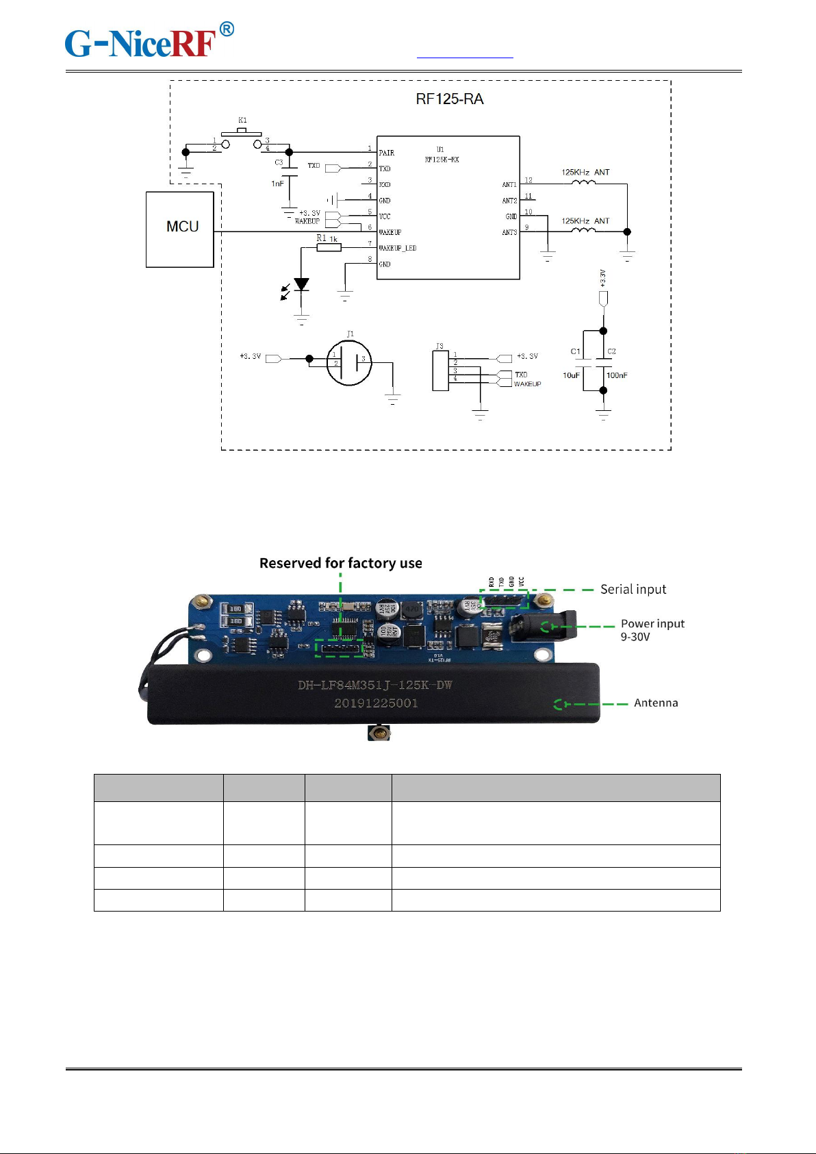
7. Typical circuit..................................................................................................................................................................9
8. Pin definition.................................................................................................................................................................10
9. Communication antenna............................................................................................................................................... 12
10. Mechanical dimension(Unit: mm)..............................................................................................................................12
11. RF125-RA operating instructions............................................................................................................................... 13
Appendix 1: Furnace temperature curve...........................................................................................................................14
Note: Revision History
Revision
Date
Comment
V1.0
2021-1
First release
V1.1
2021-11
Add RF125-TX2

www.nicerf.com RF125
NiceRF Wireless Technology Co., Ltd. Rev 1.1 -3-
sales@nicerf.com
1. Overview
The RF125-TX module, combined with our RF125-RX module, 125K wireless air wake-up and data
transmission, can be applied to PKE keyless access control, campus access control, etc.
For RF125-TX, the transmitter ID, transmission data content, and transmission time interval can be set
through the serial port.
RF125-RX, the receiver has low power consumption and wireless wake-up, can wake itself up in the
air and wake up the connected device at the same time, the receiver serial port outputs the received
wireless data. It can work in pairing mode or broadcast mode. The communication distance is 5-8
meters, far exceeding the same type of products.
RF125-RA is a full-featured wireless wake-up module that integrates RF125-RX, 125KHz antenna,
pairing button, and coin cell for battery. Just insert the battery and start to use.
2. Features
Transmitter RF125-TX wide voltage
input: 6-30V
Transmitter RF125-TX2 voltage input: 9-12V
Transmitter operating temperature range: -40
~85℃
The transmitter can send default data or customize
data content
Transmitter ID can be modified
The transmission time interval can be modified
Transmitter built-in overvoltage protection
Transmitter built-in overcurrent protection
Transmitter built-in reverse connection protection
Receiver wakes up connected device
The receiver supports pairing mode and broadcast
mode
Receiver ultra-low power consumption
Small receiver size
Long communication distance (far beyond
products of the same type)
High receiving performance
Receiver working voltage: 2.5~3.6V
Receiver operating temperature range: -40
~85℃
Receiver carrier frequency range: 15-150KHz
Low-power three-channel low-power ASK
receiver
Receive and wake up sensitivity: 80uVRMS
The lowest power consumption in the listening
state of the receiver in low power consumption
mode: <9uA
Receiver 1/2/3 channel independent operation
Programmable sensitivity adjustment range
False trigger counter
Support RTC wake-up timing

www.nicerf.com RF125
NiceRF Wireless Technology Co., Ltd. Rev 1.0 -4-
sales@nicerf.com
The receiver supports three wake-up modes:
frequency detection/pattern recognition/
location recognition
32-bit programmable Manchester wake-up mode
3. Applications
Campus access card
Industrial data collection
BRT platform gate system
PKE keyless access control
4. Electrical Characteristics(@Vcc=3.3V ANT connected to 50 ohm load)
RF125-TX /RF125-TX2
Parameters
Min.
Typ.
Max.
Unit
Condition
Temperature Parameter
Temperature
range
-40
25
85
℃
When working
-40
25
125
℃
When storing
Voltage Parameter
Operating
Voltage
12
30
V
RF125-TX
9
12
RF125-TX2
Current Parameter
Working current
-
<300
-
mA
@12V
Radio Frequency Parameters
Communication
distance
>5
m
Cooperate with our receiver
RF125-RX / RF125-RA
Parameters
Min.
Typ.
Max.
Unit
Condition
Temperature Parameter
Temperature
range
-40
25
85
℃
When working
-40
25
125
℃
When storing
Voltage Parameter
Operating
Voltage
2.5
3.3
3.6
V
Current Parameter
Receive current
-
<3
-
mA
Close to the transmitter
-
<9
-
uA
No transmission
Radio Frequency Parameters

www.nicerf.com RF125
NiceRF Wireless Technology Co., Ltd. Rev 1.1 - 5 -
sales@nicerf.com
Receiving
sensitivity
-
80
uvRMS
Communication
distance
>5
m
Cooperate with our transmitter
5. Operation Description
1. Transmitter configuration mode
The parameters of the transmitter can be modified through the serial port, including: setting the
content of transmission data, modifying the transmitter ID, setting the transmission time interval,
and reading the transmitter ID. The format of the serial port is 9600, 8, N, 1, and the data content
is (HEX) hexadecimal, with 0x0D 0x0A as the end sign. The minimum interval between two
consecutive setting commands is 100ms.
The module automatically verifies the input command. If the command is correct, the hexadecimal
return "OK\r\n" is 0x4F 0x4B 0x0D 0x0A. The error return "ERROR\r\n" hexadecimal is 0x45
0x52 0x52 0x4F 0x52 0x0D 0x0A
Users can directly connect the module to the PC through our USB adapter board, and use the
serial port assistant to operate.
(1) Set transmission data content
Set sending data:
CMD (1Byte)
Length(1Byte)
Payload(Length Byte)
0x57
CMD: 1 byte, 0x57
Length: 1 byte, the length of the data packet, excluding the command word and this byte. The
range is 0~0x2D (a packet can transmit maximum 45 (0x2D) bytes)
Payload: data content
Example:
0x57 0x05 0x01 0x02 0x03 0x04 0x05 0x0D 0x0A
Return: 0x4F 0x4B 0x0D 0x0A
CMD: 0x57
Length: 0x05
Payload: 0x01 0x02 0x03 0x04 0x05
(2) Modify transmitter ID:

www.nicerf.com RF125
NiceRF Wireless Technology Co., Ltd. Rev 1.1 - 6 -
sales@nicerf.com
ID is greater than 0x7F as an error
CMD (1Byte)
ID(7Bit)
0x58
CMD: 1 byte, 0x58
ID: 7 Bits, the range is 0~0x7F, more than 0x7F is regarded as an error
Example:
Set the ID of the transmitter to 0x01
0x58 0x01 0x0D 0x0A
Return: 0x4F 0x4B 0x0D 0x0A
(3) Read transmitter ID, return transmitter ID (1Byte)
CMD(1Byte)
0x52
Example: The ID of the transmitter is 0x01
0x52 0x0D 0x0A
Return:0x01 0x0D 0x0A
(4) Set the transmission time interval (ms) of the transmitter not to be less than 250ms
(0x00FA), if it is less than 250ms, it will be automatically set
CMD(1Byte)
TIME_H(1Byte)
TIME_L(1Byte)
0x53
CMD: 0x53
TIME_H: the upper 8 bits of the time
TIME_L: the lower 8 bits of the time
Example:
Set the interval of 1000ms, 1000 to hexadecimal is 0x03e8
The command is: 0x53 0x03 0xe8 0x0D 0x0A
Return: 0x4F 0x4B 0x0D 0x0A
2. Function description
RF125-TX worked with RF125-RX, and the receiver can work in pairing mode or broadcast
mode.
2.1 The transmission time for one packet: [32.5 + (data packet length +3) *8]ms

www.nicerf.com RF125
NiceRF Wireless Technology Co., Ltd. Rev 1.1 - 7 -
sales@nicerf.com
For example: the time required to send 45 bytes is: 416.5ms
2.2 The receiver wakes up the external device
The module will verify the content of the received data, and if the verification is correct, it will
output a 50ms high pulse to wake up the external device. If the check fails, there is no pulse
output.
Check content:
Pairing mode: check whether the ID matches the machine, the length of the data packet, and
the CRC check the data packet.
Broadcast mode: data packet length, CRC check data packet.
Figure 1 is the time taken by the receiver to receive 15 data, Wake_Up is the wake-up pulse of the
receiver, and Uart_Data is the data output through the serial port.
Figure 1
2.3 Wake-up indication:
RF125-RX will automatically wake up the external device after receiving the correct data, and the
blue LED will flash once.
6. Block Diagram
(1)RF125-TX:


www.nicerf.com RF125
NiceRF Wireless Technology Co., Ltd. Rev 1.1 - 10 -
sales@nicerf.com
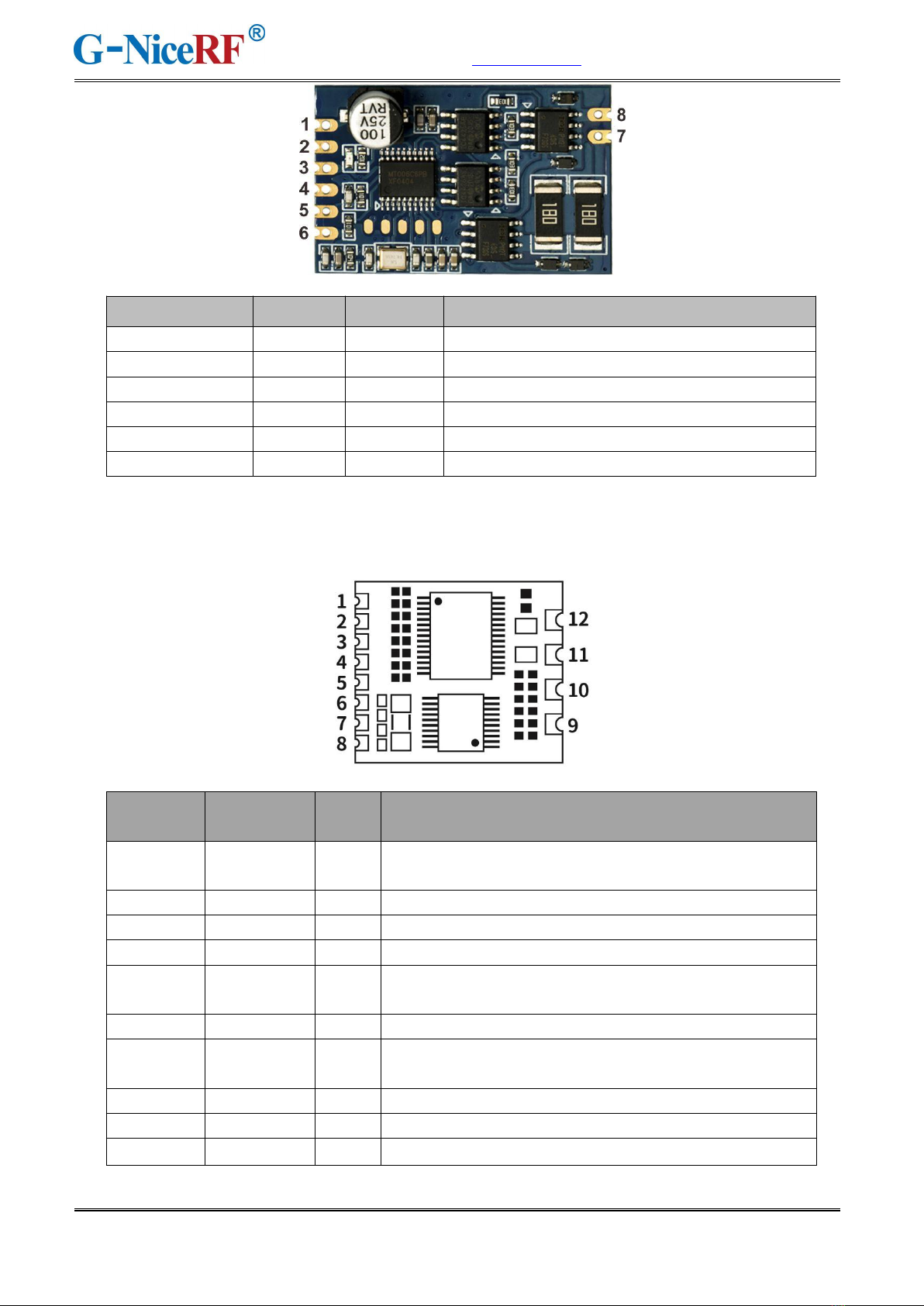
8. Pin definition
(1)RF125-TX:
(2)RF125-TX2:
Pin definition
I/O
Voltage
Description
VCC
12-30v
Can be connected to the positive pole of
12-30V power supply
GND
0
Connect the negative pole of the power supply
TXD
O
0-3.3v
Serial output port
RXD
I
0-3.3v
Serial input port
www.nicerf.com RF125
NiceRF Wireless Technology Co., Ltd. Rev 1.1 - 11 -
sales@nicerf.com
(2)RF125-RX:
Pin number
Pin
definition
I/O
Description
1
PAIR
I
Code pairing button, pull down for more than 1 second
to enter code pairing mode, usually high level
2
TXD
O
Data output port
3
RXD
I
Reserved for factory use
4,8,10
GND
Power ground
5
VCC
Can be externally connected with a positive voltage of
2.5-3.6V
6
WAKE UP
O
After receiving 125K signal, output high pulse
7
LED
O
External LED light can be connected, high level light
up
9
ANT3
I
External 125K patch antenna, the inductance is 7.2mH
11
ANT2
I
External 125K patch antenna, the inductance is 7.2mH
12
ANT1
I
External 125K patch antenna, the inductance is 7.2mH
Pin definition
I/O
Voltage
Description
1
VCC
Externally connect with DC 9-12V
2,4
GND
Externally connect with power ground
3
+3.3V
Externally connected with voltage of 2.5-3.6V
5
TXD
O
Serial output port
6
RXD
I
Serial input port
7,8
ANT
O
External 125K transmitting antenna
www.nicerf.com RF125
NiceRF Wireless Technology Co., Ltd. Rev 1.1 - 12 -
sales@nicerf.com
9. Communication antenna
The antenna is an important part of the communication system, and its performance directly affects the
indicators of the communication system. The internal matching of the module is done, and the external
antenna of the RF125-RX must meet the following parameters:
(1) @125KHZ, the inductance=7.2mH %5
(2) Q value is greater than 30
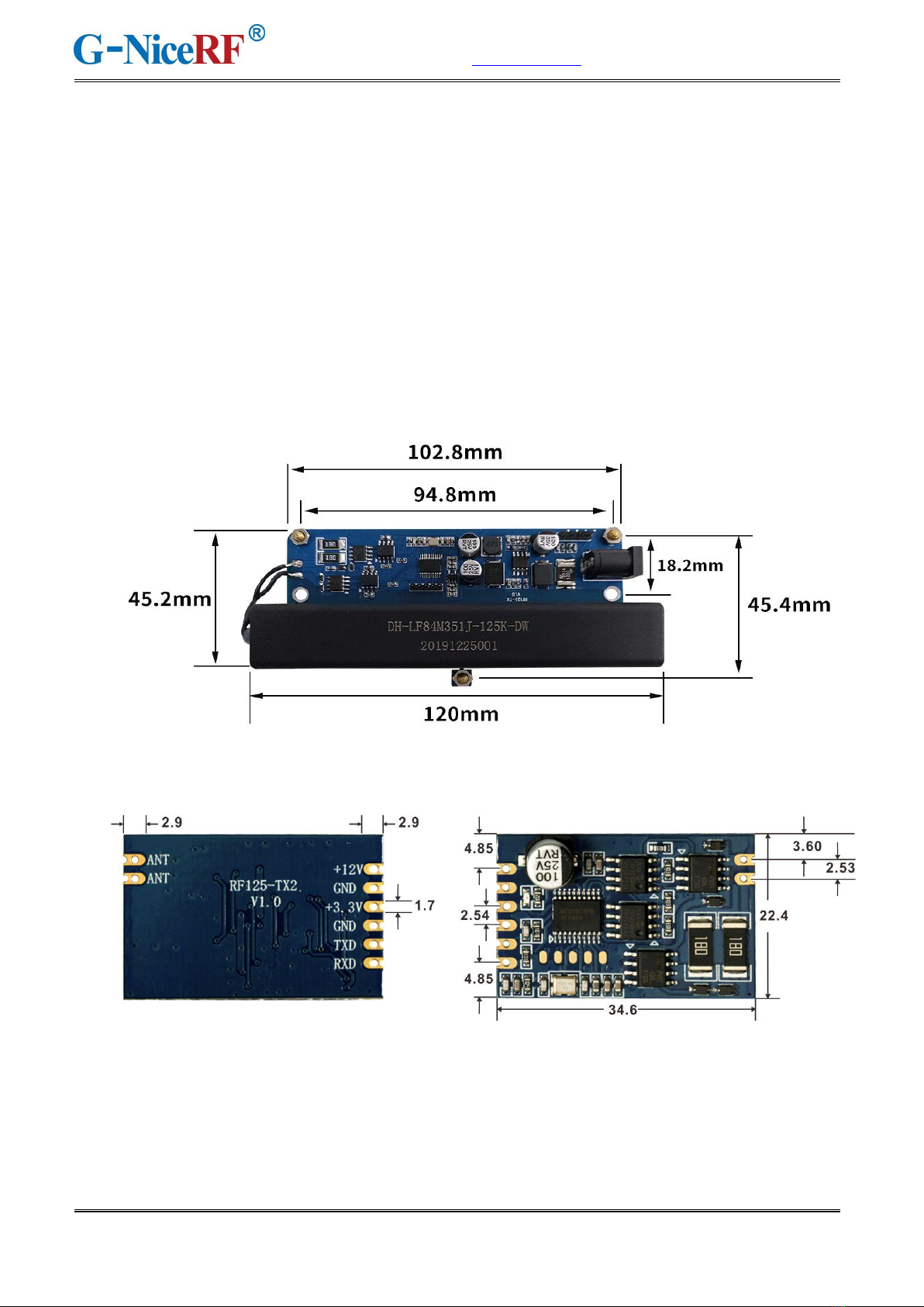
10. Mechanical dimension(Unit: mm)
(1)RF125-TX:
(2)RF125-TX2:
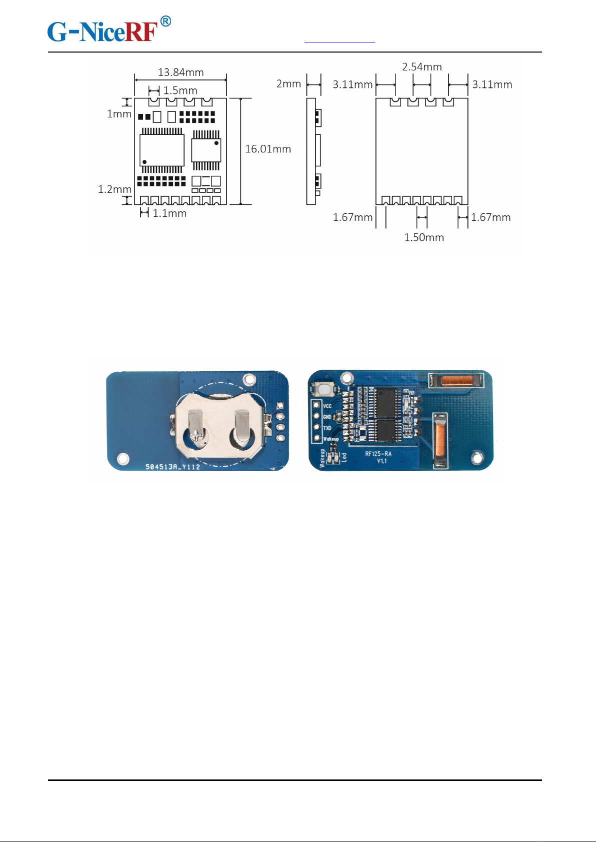
(3)RF125-RX:
www.nicerf.com RF125
NiceRF Wireless Technology Co., Ltd. Rev 1.1 - 13 -
sales@nicerf.com
11. RF125-RA operating instructions
RF125-RA is a full-featured product based on RF125-RX, which integrates RF125-RX module, two
125K antennas, battery slices, and buttons. Customers can use it directly without debugging.
pairing mode: Press and hold the button (more than two seconds), then release it, wait and observe
that the indicator light turns on, the indicator light flashes once per second, and enters the paring mode
after flashing 3 times. The transmitter will pared with the receiver which received the first packet after
entering the paring mode. After pared, only the data packet sent by the pared transmitter can be
received.
Broadcast mode: Press and hold the button (more than two seconds), then release, wait and observe
that the indicator light turns on. The indicator light flashes 2 times per second, and enters the broadcast
mode after 6 flashes. In the broadcast mode, the module can receive all the data sent by the transmitter
package.

This manual suits for next models
3
Table of contents


