Nidec Leroy-Somer LSA 50.2 Instruction Manual

LSA 50.2
Low Voltage Alternator - 4 pole
Installation and maintenance

2019.02 / j
2
Electric Power Generation Installation and maintenance
LSA 50.2
Low Voltage Alternator - 4 pole
4099 en -
SAFETY MEASURES
Before using your machine for the rst time,
it is important to read the whole of this
installation and maintenance manual.
All necessary operations and interventions
on this machine must be performed by a
qualied technician.
Our technical support service will be pleased
to provide any additional information you
may require.
The various operations described in this
manual are accompanied by recommenda-
tions or symbols to alert the user to potential
risks of accidents. It is vital that you under-
stand and take notice of the following war-
ning symbols.
Warning symbol for an operation capable
of damaging or destroying the machine
or surrounding equipment.
Warning symbol for general danger to
personnel.
Warning symbol for electrical danger to
personnel.
SAFETY INSTRUCTIONS
We wish to draw your attention to the
following 2 safety measures which must be
complied with:
a) During operation, do not allow anyone
to stand in front of the air outlet guards,
in case anything is ejected from them.
b) Do not allow children younger than 14
to go near the air outlet guards.
A set of self-adhesive stickers depicting the
various warning symbols is included with
this maintenance manual. They should be
positioned as shown in the drawing below
once the machine has been fully installed.
WARNING
The alternators must not be put into
service until the machines in which they
are to be incorporated have been
declared compliant with Directives EC
and plus any other directives that may be
applicable.
This manual is to be given to the end
user.
The range of electric alternators and
their derivatives, manufactured by us or
on our behalf, comply with the technical
requirements of the customs Union
directives (EAC).
© - We reserve the right to modify the
characteristics of this product at any time in
order to incorporate the latest technological
developments. The information contained
in this document may therefore be changed
without notice.
This document may not be reproduced in
any form without prior authorisation.
All brands and models have been registered
and patents applied for.
WARNING
This manual concerns the alternator which you have just purchased.
We wish to draw your attention to the contents of this maintenance manual.

2019.02 / j
3
Electric Power Generation Installation and maintenance
LSA 50.2
Low Voltage Alternator - 4 pole
4099 en -
CONTENTS
1 - RECEIPT ............................................................................................................ 4
1.1 - Standards and safety measures............................................................................... 4
1.2 - Inspection ................................................................................................................. 4
1.3 - Identication ............................................................................................................. 4
1.4 - Storage ..................................................................................................................... 4
1.5 - Applications .............................................................................................................. 4
1.6 - Usage restrictions..................................................................................................... 4
2 - TECHNICAL CHARACTERISTICS.................................................................... 5
2.1 - Electrical characteristics ........................................................................................... 5
2.2 - Mechanical characteristics ....................................................................................... 5
3 - INSTALLATION.................................................................................................. 6
3.1 - Assembly .................................................................................................................. 6
3.2 - Checks prior to rst use............................................................................................ 6
3.3 - Terminal connection diagrams.................................................................................. 7
3.4 - Commissioning ....................................................................................................... 10
3.5 - Setting up ............................................................................................................... 10
4 - SERVICING - MAINTENANCE......................................................................... 11
4.1 - Safety measures......................................................................................................11
4.2 - Routine maintenance...............................................................................................11
4.3 - Bearings ................................................................................................................. 12
4.4 - Mechanical defects................................................................................................. 12
4.5 - Electrical faults ....................................................................................................... 13
4.6 - Dismantling, reassembly ........................................................................................ 15
4.7 - Installation & maintenance of the PMG .................................................................. 17
4.8 - Table of characteristics ...................................................................................... 17-18
5 - SPARE PARTS................................................................................................. 19
5.1 - First maintenance parts .......................................................................................... 19
5.2 - Technical support service ....................................................................................... 19
5.3 - Accessories ........................................................................................................... 19
5.4 - Exploded views, parts list and tightening torque .................................................... 20
Disposal and recycling instructions
Declaration of EC compliance and incorporation

2019.02 / j
4
Electric Power Generation
LSA 000-1-006 e
Moteurs Leroy-Somer - Boulevard Marcellin Leroy,
CS 10015 - 16915 Angoulême Cedex 9 - France
IEC 60034 - 1 & 5. / ISO 8528 - 3. / NEMA MG1 - 32 & 33.
R
CUS Made in ............................
166631
IPLSA
N°:
Th.class.
A.V.R. Excit.
Excit. values full load : V / A
at no load : A
D.E. bearing
N.D.E. bearing
Altitude : m
kVA
kW
A
V
kVA
kW
A
Weight : kg
r.p.m.
P.F. :
Hz
RATINGS
Voltage
Phase
Conn.
Contin.
P.R.
B.R.
40°C.
Std by
27°C.
Date :
Installation and maintenance
LSA 50.2
Low Voltage Alternator - 4 pole
4099 en -
1 - RECEIPT
1.1 - Standards and safety
measures
Our alternators comply with most
international standards.
See the EC Declaration of Incorporation on
the last page.
1.2 - Inspection
On receipt of your alternator, check that it
has not suffered any damage in transit. If
there are obvious signs of knocks, contact
the transporter (you may be able to claim
on their insurance) and after a visual
check, turn the machine by hand to detect
any malfunction.
1.3 - Identication
The alternator is identied by means of a
nameplate xed on the machine (see
drawing).
Make sure that the nameplate on the
machine conforms to your order.
So that you can identify your alternator
quickly and accurately, we suggest you ll in
its specications on the nameplate below.
1.4 - Storage
Prior to commissioning, machines should
be stored :
- away from humidity (< 90%); after a long
period of storage, check the machine
insulation. To prevent the bearings from
becoming marked, do not store in an
environment with signicant vibration.
1.5 - Application
These alternators are mainly designed to
produce electricity in the context of
applications involving the use of
generators.
1.6 - Usage restrictions
Use of the machine is restricted to operating
conditions (environment, speed, voltage,
power, etc) compatible with the characteri-
stics indicated on the nameplate.

2019.02 / j
5
Electric Power Generation Installation and maintenance
LSA 50.2
Low Voltage Alternator - 4 pole
4099 en -
2 - TECHNICAL CHARACTERISTICS
2.1 - Electrical characteristics
This alternator is a machine without
sliprings or revolving eld brushes, wound
as “2/3 pitch”; 6 wire, with class H
insulation and a eld excitation system
available in either AREP or PMG version
(see diagrams and AVR maintenance
manual).
• Electrical options
- Stator temperature detection sensors
- Bearing sensors (PTC, PT 100, ...)
- Space heaters
- Terminal box with connector links for
mounting protection or measurement C.T.
In order to conform to standard EN 61000-
6.3, EN 61000-6.2, EN 55011, the R791
interference suppression kit is needed.
2.2 - Mechanical characteristics
- Steel frame
- Cast iron end shields
- Protected ball bearings, permanently
greased
- Mounting arrangement: single-bearing
with feet and SAE anges/coupling discs,
twin-bearing with SAE ange and standard
cylindrical shaft extension
- Drip-proof machine, self-cooled
- Degree of protection: IP 23
• Mechanical options
- Regreasable ball bearings
- Protection against harsh environments
- Air inlet lter, air outlet labyrinth seals: IP 44
To prevent excessive temperature rise
caused by clogged lters, it is advisable to
monitor the stator winding with thermal
sensors (PTC or PT100).
- Bearing temperature detection sensors
T1 T2 T3
T4 T5 T6
Surge suppressor
5+ 6-
R450
Aux. windings
Exciter
Field
Armature
MAIN FIELD
Voltage reference
STATOR : 6-wire (marked T1 to T6)
T1 T2 T3
T4 T5 T6
Surge suppressor
5+ 6-
R450
PMG
Exciter
Field
Armature
MAIN FIELD
Voltage reference
STATOR : 6-wire (marked T1 to T 6)
• AREP three-phase 6-wire
• PMG three-phase 6-wire

2019.02 / j
6
Electric Power Generation Installation and maintenance
LSA 50.2
Low Voltage Alternator - 4 pole
4099 en -
3 - INSTALLATION
Personnel undertaking the various
operations indicated in this section must
wear personal protective equipment
appropriateformechanicaland electrical
hazards.
3.1 - Assembly
All mechanical handling operations
must be undertaken using suitable
equipment and the machine must be
horizontal.Checkhow much the machine
weighs before choosing the lifting tool.
During this operation, do not allow
anyone to stand under the load.
• Handling
The generously-sized lifting eyes are for
handling the alternator only. They must not
be used to lift the genset. The choice of
lifting hooks or handles should be
determined by the shape of the lifting eyes.
Choose a lifting system which respects the
integrity and the environment of the
machine.
During this operation, do not allow
anyone to stand under the load.
• Single-bearing coupling
Before coupling, check the compatibility
between the alternator and the engine by
performing:
- undertaking a torsional analysis of the
transmission (alternators data are available
on request),
- checking the dimensions of the ywheel
and its housing, the ange, coupling discs
and offset.
WARNING
When coupling the alternator to the
prime mover, do not use the fan to turn
the alternator or rotor.
The holes of the coupling discs should
be aligned with the ywheel holes by
cranking the engine.
Make sure the machine is securely
bedded in position during coupling.
Check that there is lateral play on the
crankshaft.
• Double-bearing coupling
- Semi-exible coupling
Careful alignment of the machines is
recommended, checking that the lack of
concentricity and parallelism of both parts
of the coupling do not exceed 0.1 mm.
This alternator has been balanced with a
1/2 key.
• Location
The room where the alternator is placed
must be ventilated to ensure that the
ambient temperature cannot exceed the
data on the nameplate.
3.2 - Checks prior to rst use
• Electrical checks
Under no circumstances should an
alternator, new or otherwise, be operated
if the insulation is less than 1 megohm
for the stator and 100,000 ohms for the
other windings.

2019.02 / j
7
Electric Power Generation Installation and maintenance
LSA 50.2
Low Voltage Alternator - 4 pole
4099 en -
There are 2 possible methods for restoring
the above minimum values.
a) Dry out the machine for 24 hours in a
drying oven at a temperature of 110 °C
(without the regulator).
b) Blow hot air into the air intake, having
made sure that the machine is rotating with
the exciter eld disconnected.
Note : Prolonged standstill
In order to avoid these problems, we
recommend the use of space heaters, as
well as turning over the machine from time
to time. Space heaters are only really
effective if they are working continuously
while the machine is stopped.
Ensure that the alternator has the degree
of protection matching the dened
environmental conditions.
• Mechanical checks
Before starting the machine for the rst time,
check that:
- all xing bolts are tight,
- the length of bolt and the tightening torque
are correct,
- the cooling air is drawn in freely,
- the protective grills and housing are cor-
rectly in place,
- the standard direction of rotation is clock-
wise as seen from the drive end (phase
rotation in order 1 - 2 - 3).
For anti-clockwise rotation, swap 2 and 3.
- the winding connection corresponds to the
site operating voltage (see section 3.3).
3.3 - Terminal connection diagrams
To modify the connection, change the
position of the stator cables on the terminals.
The winding code is specied on the
nameplate.
Any intervention on the alternator
terminals during reconnection or checks
should be performed with the machine
stopped. In no case should the internal
connections in the terminal box be
subjected to stresses due to cables
connected by the user.
WARNING

2019.02 / j
8
Electric Power Generation Installation and maintenance
LSA 50.2
Low Voltage Alternator - 4 pole
4099 en -
• AREP or PMG three-phase 6-wire
Connection code L.L voltage Factory connection
3-phase
N
T1
T4
T3
T6
T5
T2
L1(U)
L3(W) L2(V)
D
L1(U)
L3(W)
T1
T4T3
T6
T5 T2
L2(V)
F
3-phase
(*)
Winding
60 Hz50 Hz
380 - 415 380 - 480
440
380 - 416
-
-
-
6S
7S
8S
Winding
60 Hz50 Hz
R450 voltage sensing:
0 => (T3) / 220 V => (T2)
9S
600
220 - 240
220 - 240
220 - 277
240 - 254 -
-
6S
7S
8S
With winding 9: R450 + transfo voltage sensing (Diagram on request)
NDE
L1(U)
L2(V)
L3(W)
T4
T6
T5
T1
T2
T3
N
If the alternator is reconnected, check that the AVR is sensing the voltage!
As an option, the factory can provide special connector bars to make these connections (*).
R450 voltage sensing:
0 => (T3) / 380 V => (T2)
NDE
L1(U)
L2(V)
L3(W)
T4
T6
T5
T1
T2
T3

2019.02 / j
9
Electric Power Generation Installation and maintenance
LSA 50.2
Low Voltage Alternator - 4 pole
4099 en -
• Option connection diagram
R791 T interference suppression kit (standard for CE marking) External voltage potentiometer
Black
Black
Black
Blue
Green/Yellow
Connections
D F
T1 T1
T2 T2
T3 T3
N
Voltage adjustment via remote
potentiometer
ST
1000 ohms
Connection of current transformer Space heater PTC stator sensors
Shield PT100 White
Neutral link
White
Red
Red
6 wires
- PH 1
In/4 Secondary 1 A
D connection
P1
P2 T4
T4
Ph1
Ph2
Ph3
101
102
103
104
130 ºC
blue wire
150 ºC
black wire
180 ºC
red/white
wire
500W - 220 V
121
122
122
White
Red
Red
123
124
124
DE
NDE
122
122
124
124
123
121 103
104
104
105
106
106
107
108
108
White
Red Red Red
Red RedRed
103
104
104
PH 1
White
105
106
106
PH 2
White
107
108
108
PH 3

2019.02 / j
10
Electric Power Generation Installation and maintenance
LSA 50.2
Low Voltage Alternator - 4 pole
4099 en -
• Connection checks
Electrical installations must comply with
the current legislation in force in the
country of use.
Check that:
- The residual circuit-breaker conforms to
legislation on protection of personnel, in
force in the country of use, and has been
correctly installed on the alternator power
output as close as possible to the alternator.
(In this case, disconnect the wire of the
interference suppression module linking the
neutral).
- Any protection devices in place have not
been tripped.
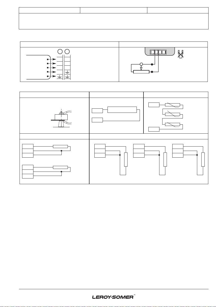
- If there is an external AVR, the connections
between the alternator and the cabinet are
made in accordance with the connection
diagram.
- There is no short-circuit phase-phase or
phase-neutral between the alternator output
terminals and the generator set control
cabinet (part of the circuit not protected by
circuitbreakers or relays in the cabinet).
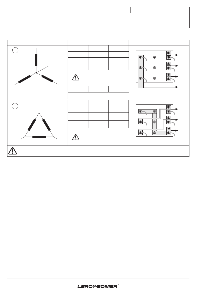
- The machine should be connected with the
busbar separating the terminals as shown in
the terminal connection diagram.
- The alternator earth terminal inside the
terminal box is connected to the electrical
earth circuit
- The earth terminal is connected to the
frame.
The connections inside the terminal box
must never be subjected to stress due to
cables connected by the user.
Diameter M6 M8 M10 M12
Torque 4 Nm 10 Nm 20 Nm 35 Nm
Tolerance ± 15%
3.4 - Commissioning
The machine can only be started up and
used if the installation is in accordance
with the regulations and instructions
dened in this manual.
The machine is tested and set up at the
factory. When rst used with no load, make
sure that the drive speed is correct and
stable (see the nameplate). With the
regreasable bearing option, we recommend
greasing the bearings at the time of
commissioning (see section 4.3).
On application of the load, the machine
should achieve its rated speed and voltage;
however, in the event of abnormal operation,
the machine setting can be altered (follow
the adjustment procedure in section 3.5). If
the machine still operates incorrectly, the
cause of the malfunction must be located
(see section 4.5).
3.5 - Setting up
The various adjustments during tests
must be made by a qualied engineer.
Ensure that the drive speed specied on
the nameplate is reached before
commencing adjustment.
After operational testing, replace all
access panels or covers.
TheAVR is used to make any adjustments
to the machine.

2019.02 / j
11
Electric Power Generation Installation and maintenance
LSA 50.2
Low Voltage Alternator - 4 pole
4099 en -
4 - SERVICING - MAINTENANCE
4.1 - Safety measures
Servicing or troubleshooting must be
carried out strictly in accordance with
instructions so as to avoid the risk of
accidents and to maintain the machine in
its original state.
All such operations performed on the
alternator should be undertaken by
personnel trained in the commissioning,
servicing and maintenance of electrical
and mechanical components, who must
wear personal protective equipment
appropriateformechanicaland electrical
hazards.
Before any intervention on the machine,
ensure that it cannot be started by a manual
or automatic system and that you have
understood the operating principles of the
system.
Warning : During and after running, the
alternator will reach temperatures hot
enough to cause injury, such as burns.
4.2 - Routine maintenance
• Checks after start-up
After approximately 20 hours of operation,
check that all xing bolts on the machine are
still tight, plus the general state of the
machine and the various electrical
connections in the installation.
• Electrical servicing
Commercially-available volatile degreasing
agents can be used.
Do not use: trichlorethylene, perchlo-
rethylene,trichloroethaneorany alkaline
products.
These operations must be performed at
a cleaning station, equipped with a
vacuum system that collects and ushes
out the products used.
The insulating components and the
impregnation system are not at risk of
damage from solvents. Avoid letting the
cleaning product run into the slots.
Apply the product with a brush, sponging
frequently to avoid accumulation in the
housing. Dry the winding with a dry cloth. Let
any traces evaporate before reassembling
the machine.
• Mechanical servicing
Cleaning the machine using water or a
highpressure washer is strictly prohi-
bited. Any problems arising from such
treatment are not covered by our
warranty.
Degreasing: Use a brush and detergent
(suitable for paintwork).
Dusting: Use an air gun.
If the machine is tted with air inlet and outlet
lters, the maintenance personnel should
clean them routinely at regular intervals. In
the case of dry dust, the lter can be cleaned
using compressed air and/or replaced if it is
clogged.
After cleaning the alternator, it is essential to
check the winding insulation (see sections
3.2 and 4.5).
WARNING
WARNING

2019.02 / j
12
Electric Power Generation Installation and maintenance
LSA 50.2
Low Voltage Alternator - 4 pole
4099 en -
4.3 - Bearings
The bearings are permanently greased Approximate life of the grease (depending on use) = 20,000
hours or 3 years.
As an option, the bearings are regreasable Regreasing interval: 3600 hrs of operation
DE bearing: Amount of grease: 60 gr
NDE bearing: Amount of grease: 50 gr
Standard grease LITHIUM - standard - NLGI 3
Grease used in the factory ESSO - Unirex N3
It is imperative to lubricate the alternator during operation and on rst use.
Before using another grease, check for compatibility with the original one.
4.4 - Mechanical defects
Fault Action
Bearing
Excessive overheating of one or
both bearings
(bearing temperature 80°C above
the ambient temperature)
- If the bearing has turned blue or if the grease has turned
black, change the bearing.
- Bearing not fully locked (abnormal play in the bearing cage)
- End shields incorrectly aligned
Abnormal
temperature
Excessive overheating of
alternator frame (more than
40° C above the ambient
temperature)
- Air ow (inlet-outlet) partially clogged or hot air is being
recycled from the alternator or engine
- Alternator operating at too high a voltage (>105% of Un on
load)
- Alternator overloaded
Vibrations
Too much vibration
- Misalignment (coupling)
- Defective mounting or play in coupling
- Rotor balancing fault (Engine - Alternator)
Excessive vibration and humming
noise coming from the machine
- Phase imbalance
- Stator short-circuit
Abnormal
noise
Alternator damaged by a
signicant impact, followed by
humming and vibration
- System short-circuit
- Misparalleling
Possible consequences
- Broken or damaged coupling
- Broken or bent shaft end
- Shifting and short-circuit of main eld
- Fan fractured or coming loose on shaft
- Irreparable damage to rotating diodes/AVR, surge suppressor

2019.02 / j
13
Electric Power Generation Installation and maintenance
LSA 50.2
Low Voltage Alternator - 4 pole
4099 en -
4.5 - Electrical faults
Fault Action Effect Check/Cause
No voltage
at no load on
start-up
Connect a new
battery of 4 to 12
volts to terminals
E- and E+,
respecting the
polarity, for 2 to 3
seconds
The alternator builds up and
its voltage is still correct
when the battery is removed
- Lack of residual magnetism
The alternator builds up but
its voltage does not reach
the rated value when the
battery is removed
- Check the connection of the voltage
reference to the AVR
- Faulty diodes
- Armature short-circuit
The alternator builds up but
its voltage disappears when
the battery is removed
- Faulty AVR
- Field windings disconnected (check winding)
- Main eld winding open circuit (check the
resistance)
Voltage too
low
Check the drive
speed
Correct speed
Check the AVR connections (AVR may be
faulty)
- Field windings short-circuited
- Rotating diodes burnt out
- Main eld winding short-circuited (check the
resistance)
Speed too low
Increase the drive speed
(Do not touch the AVR voltage pot. (P2) before
running at the correct speed)
Voltage too
high
Adjust AVR
voltage
potentiometer
Adjustment ineffective - Faulty AVR
- 1 faulty diode
Voltage
oscillations
Adjust AVR
stability
potentiometer
If no effect : try normal / fast
recovery modes (ST2)
- Check the speed : possibility of cyclic
irregularity
- Loose connections
- Faulty AVR
- Speed too low when on load (or LAM set too
high)
Voltage
correct
at no load
and too low
when on
load
Run at no load
and check the
voltage between
E+ and E- on the
AVR
Voltage between E+ and E-
AREP / PMG < 10V - Check the speed (or LAM set too high)
Voltage between E+ and E-
AREP / PMG > 15V
- Faulty rotating diodes
- Short-circuit in the main eld (check the
resistance)
- Faulty exciter armature
Voltage
disappears
during
operation
Check the AVR,
the surge
suppressor, the
rotating diodes,
and replace any
defective
components
The voltage does not return
to the rated value.
- Exciter winding open circuit
- Faulty exciter armature
- Faulty AVR
- Main eld open circuit or short-circuited

2019.02 / j
14
Electric Power Generation Installation and maintenance
LSA 50.2
Low Voltage Alternator - 4 pole
4099 en -
• Checking the winding
You can check the winding insulation by
performing a high voltage test. In this case,
you must disconnect all AVR wires.
WARNING
Damage caused to the AVR in such
conditions is not covered by our
warranty.
• Checking the windings and rotating
diodes using separate excitation
During this procedure, make sure that
the alternator is disconnected from any
external load and inspect the terminal
box to check that the connections are
fully tightened.
1) Stop the unit, disconnect and isolate the
AVR wires.
2) There are two ways of creating an
assembly with separate excitation.
Assembly A: Connect a 12 V battery in
series with a rheostat of approximately
50 ohms - 300 W and a diode on both exciter
eld wires (5+) and (6-).
6 - 5 +
1A diode
12V battery
Rh. 50 -300W
-
+
A
SSEMBLY A
Field
Assembly B: Connect a “Variac” variable
power supply and a diode bridge on both
exciter eld wires (5+) and (6-).
Both these systems should have
characteristics which are compatible with
the eld excitation power of the machine
(see the nameplate).
3) Run the unit at its rated speed.
4) Gradually increase the exciter eld
current by adjusting the rheostat or the
variac and measure the output voltages on
L1 - L2 - L3, checking the excitation voltage
and current at no load (see the machine
nameplate or ask for the factory test report).
When the output voltage is at its rated value
and balanced within 1% for the rated
excitation level, the machine is in good
working order. The fault therefore comes
from the AVR or its associated wiring (ie.
sensing, auxiliary windings).
1A diode
-
+
6 - 5 +
Variac AC
220V
DC
12V
50
60
70
80
90
100
40
30
20
10
0
ASSEMBLY BField
• Checking the diode bridge
A diode in good working order should allow
the current to ow only in the anode-to-
cathode direction.
C
A
Anode Cathode
- -
+ +
~ ~ ~
C C C
A A A
C C C
A A A
~ ~ ~
-
C
A
+
-
C
A
+

2019.02 / j
15
Electric Power Generation Installation and maintenance
LSA 50.2
Low Voltage Alternator - 4 pole
4099 en -
4.6 - Dismantling, reassembly
During the warranty period, this
operation should only be carried out in
an approved workshop or in our factory,
otherwise the warranty may be
invalidated.
Whilst being handled, the machine
should remain horizontal (rotor not
locked in position). Check how much the
machine weighs before choosing the
lifting method.
• Tools required
To fully dismantle the alternator, we
recommend using the tools listed below :
- 1 ratchet spanner + extension
- 1 torque wrench
- 1 set of at spanners : 8 mm, 10 mm, 18 mm
- 1 socket set : 8, 10, 13, 16, 18, 21, 24, 30 mm
- 1 socket with male ferrule: 5 mm
- 1 puller
• Screw tightening torque
See section 5.4.
• Access to diodes
- Open the air intake grille (51).
- Disconnect the diodes.
- Disconnect the diodes using an ohmmeter
or a battery lamp.
- Remove the surge suppressor (347).
- Remove the 6 “H” mounting nuts for the
diode bridges on the support.
- Change the tted caps, respecting the
polarity.
• Access to connections and the
regulation system
Access directly by removing the box lid (48)
or the AVR access door (466).
• Replacing the NDE bearing
- Remove the air intake grille (51).
- Remove the lid of the protective cover (48)
and the side panels (366) and (367).
- Remove the hook (21) and the cover rear
panel (365).
-Replacethehook(21)inordertomanipulate
the ange.
- Disconnect the exciter wires (5+,6-).
- Remove the screws (72) from the inner
bearing cap (78).
- Remove the screws (37).
- Remove the shield (36).
- Take out the antifriction bearing (70) using
a puller with a central screw (see drawing
below).
- Fit the new antifriction bearing onto the
shaft after heating it by induction to
approximately 80 °C.
- Mount the new preloading (wavy) washer
(79) + the new “O” ring seal (349) in the
shield (36).
- Screw a threaded rod into the inner bearing
cap (78).
- Ret the end shield on the machine using
a dowel and nut in the shaft extension (see
drawing).

2019.02 / j
16
Electric Power Generation Installation and maintenance
LSA 50.2
Low Voltage Alternator - 4 pole
4099 en -
- Slide the threaded rod into the shield hole
to make it easier to assemble (see diagram).
Rotor
NDE shield
Dowel
Nut
Threaded rod
4
78
36
- Fit a inner bearing cap screw (78), remove
the threaded rod, t the other screws and
tighten up the assembly.
- Tighten the shield screws (37).
- Reconnect exciter eld wires E+, E-.
- Finish reassembling the cover.
WARNING
When dismantling the shields, you will
need to change the antifriction bearings,
the “O” ring seal, the preloading (wavy)
washer and adhesive paste.
• Replacing the DE bearing
- Remove the air outlet grille (33).
- Remove the screws (31) from the DE shield
and the 4 screws (62) from the inner bearing
retainer.
- Remove the shield (30).
- Take out the ball bearing (60) using a puller
with a central screw.
- Fit the new bearing, after heating it by
induction to approximately 80 °C.
- Screw two threaded rods into the inner
bearing cap (68).
- Ret the shield (30) on the machine.
- Slide the threaded rods into the shield
holes to make it easier to assemble (see
basic diagram).
- Tighten the bottom inner bearing cap
screws (78), remove the threaded rod and t
the other screws.
- Tighten the shield screws (31).
- Ret the air outlet grille (33).
• Dismantling the rotor assembly
- Remove the NDE shield (36).
- Remove the DE shield (30) if it is a twin-
bearing machine.
- Support the DE rotor (4) with a strap or with
a support constructed in accordance with
the following drawing.
- Move the strap as the rotor moves in order
to distribute the weight evenly over it.
WARNING
When dismantling the rotor involves
changing parts or rewinding, the rotor
must be rebalanced.

2019.02 / j
17
Electric Power Generation Installation and maintenance
LSA 50.2
Low Voltage Alternator - 4 pole
4099 en -
• Reassembling the machine
- Mount the rotor (4) in the stator (1) (see
drawing above)
taking care not to knock the windings.
- Slide the threaded rod into the shield hole
to make it easier to assemble (see diagram).
- Fit an inner bearing cap screw (78), remove
the threaded rod, t the other screw and
tighten up the assembly.
- Tighten the shield screws (37).
- Reconnect exciter eld wires E+, E-.
- Finish reassembling the cover.
- Ret the ange (30) on the stator (1).
- Tighten the screws (31).
If using a twin-bearing machine:
- Finish reassembling the cover.
- Screw a threaded rod into the inner bearing
cap (68).
- Ret the shield (30) on the machine.
- Slide the threaded rod into the shield hole
to make it easier to assemble (see diagram).
- Fit the inner bearing cap screws (68),
remove the threaded rod, t the other screw
and tighten up the assembly.
- Tighten the shield screws (31).
- Ret the air outlet grille (33).
- Check that the machine assembly is
correctly mounted and that all screws are
tightened.
• Dismantling and reassembly of the
lters
- Remove the grille (417) then take out the
lter (418). Change the lter if necessary; for
cleaning the lter (§ 4.2).
To replace, follow the instructions in reverse
order.
- On certain versions, the lters are
incorporated in the terminal box panels.
418
417
51
4.7 - Installation and maintenance of
the PMG
The PMG reference is PMG 5.
See the PMG manual ref : 4211.
4.8 - Table of characteristics
Table of average values.
Alternator - 4 poles - 50 Hz - Standard
winding No. 6.
(400V for the excitation values).
The voltage and current values are given for
no-load operation and operation at rated
load with separate eld excitation. All values
are given at ± 10% and may be changed
without prior notication (for exact values,
consult the test report).

2019.02 / j
18
Electric Power Generation Installation and maintenance
LSA 50.2
Low Voltage Alternator - 4 pole
4099 en -
• Average values
Resistances at 20°C (Ω)
Type L/N
stator Rotor Exciter
eld Armature
S4 0.00208 0.390 11.1 0.06
M6 0.00159 0.434 11.1 0.06
L7 0.00137 0.461 11.1 0.06
L8 0.00123 0.506 11.1 0.06
VL10 0.00103 0.555 11.1 0.06
Resistance of AREP auxiliary windings
at 20°C (Ω)
Type Auxil wdg:
X1, X2
Auxil wdg:
Z1, Z2
S4 0.094 0.144
M6 0.085 0.145
L7 0.089 0.170
L8 0.082 0.132
VL10 0.077 0.143
Field excitation current i exc (A)
Symbols: «i exc»: excitation current of the
exciter eld.
Type No load At rated load
S4 0.9 4
M6 0.9 4.1
L7 1 4
L8 0.9 3.9
VL10 0.9 3.7
For 60 Hz machines, the «i exc» values are
approximately 5 to 10% lower.
• Voltage of auxiliary windings at no load
Type Auxil wdg:
X1, X2
Auxil wdg:
Z1, Z2
50 Hz 100 V 5 V
60 Hz 120 V 6 V
• Table of weights
(values given for information only)
Type Total weight (kg) Rotor (kg)
S4 2330 831
M6 2530 932
L7 2800 1003
L8 3010 1081
VL10 3300 1191

2019.02 / j
19
Electric Power Generation Installation and maintenance
LSA 50.2
Low Voltage Alternator - 4 pole
4099 en -
5 - SPARE PARTS
5.1 - First maintenance parts
Emergency repair kits are available as an
option.
They contain the following items :
Emergency kit AREP ALT 502 KS 001
AVR R450 -
Diode bridge assembly -
Surge suppressor -
Single-bearing kit ALT 502 KB 002
Non drive end bearing -
«O» ring -
Preloading (wavy) washer -
Double-bearing kit ALT 502 KB 001
Non drive end bearing -
Drive end bearing -
«O» ring -
Preloading (wavy) washer -
5.3 - Accessories
• Space heater when stopped
The space heater must run as soon as the
alternator stops. It is installed at the rear of
the alternator. Its standard power is 500W
with 220V or 250W with 110V on request.
Caution : the power supply is present
when the alternator has stopped.
• Temperature probes with thermistors
(PTC)
These are thermistor triplets with a positive
temperature coefcient installed in the
stator winding (1 per phase). There can be a
maximum of 2 triplets in the winding (at 2
levels : warning and trip) and 1 or 2
thermistors in the bearings.
These sensors must be linked to adapted
sensing relays (supplied optionally).
Cold resistance of cold thermistor sensors :
100 to 250 Ω per probe.
• Connection accessories
- 6-wire machines
Requirements for coupling (F):
- 3 links.
5.2 - Technical support service
Our technical support service will be
pleased to provide any additional
information you may require.
For all spare parts orders or technical
support requests, send your request to
service.epg@leroy-somer.com or your
closest contact, whom you will nd at
www.lrsm.co/support indicating the comp-
lete type of machine, its number and the
information indicated on the nameplate.
Part numbers should be identied from the
exploded views and their description from
the parts list.
To ensure that our products operate correctly
and safely, we recommend the use of
original manufacturer spare parts.
In the event of failure to comply with this
advice, the manufacturer cannot be held
responsible for any damage.
After operational testing, it is essential to
replace all access panels or covers.

2019.02 / j
20
Electric Power Generation
33
320
15
41
128
30
343 100
198
124
120
70
51
78
90
79
71
349
323 325 322
50
366
42
41
466
48
47
367
466
130
21
36
Installation and maintenance
LSA 50.2
Low Voltage Alternator - 4 pole
4099 en -
5.4 - Exploded view, parts list and tightening torque
• Single-bearing
Table of contents
Other Nidec Portable Generator manuals

Nidec
Nidec LEROY-SOMER TAL A40 User manual

Nidec
Nidec LEROY-SOMER LSA 44.3 Instruction Manual

Nidec
Nidec LEROY-SOMER LSA 52.2 MHV Instruction Manual

Nidec
Nidec Leroy-Somer TAL 042 Instruction Manual

Nidec
Nidec Leroy-Somer TAL 040 Instruction Manual

Nidec
Nidec AA28438000 User manual

Nidec
Nidec 4P10 User manual

Nidec
Nidec LEROY-SOMER LSA 49.3 Instruction Manual