1. GENERAL INFORMATION
1.1 INTRODUCTION
1.1.0 General points
This manual provides installation, operating and
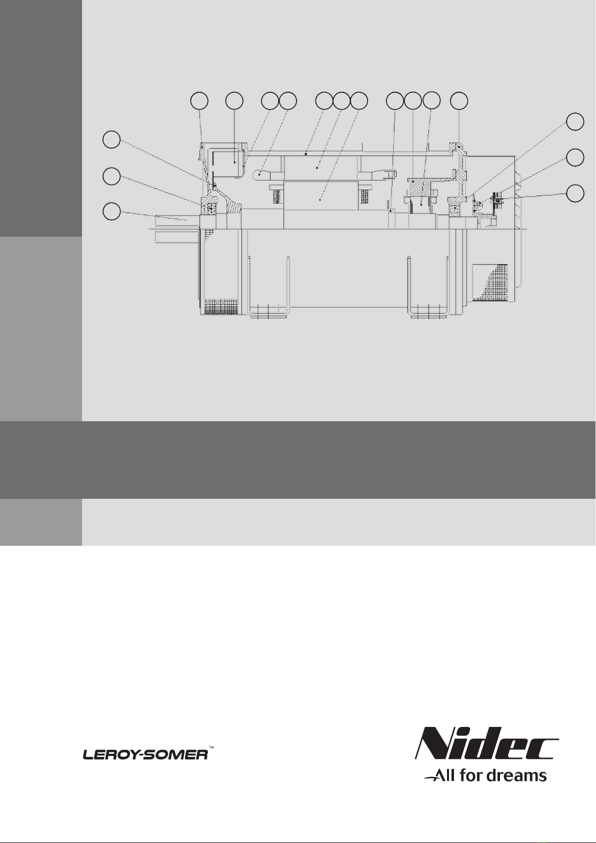
maintenance instructions for synchronous machines. It also
describes the basic construction of these machines. This
manual is general ; it applies to an entire group of
synchronous generators. Additionally, in order to make
information-finding easier, Section 1, "Characteristics and
Performance", has been included, describing the machine
completely (type of construction, type of bearing, protection
index, and so forth...); this will enable you to determine
exactly the chapters which apply to your machine.
This synchronous machine has been designed for a
maximum length of service. To achieve this, it is necessary
to pay special attention to the chapter concerning the
periodic maintenance schedule for the machines.
1.1.1 Safety notes
The warnings "DANGER, CAUTION, NOTE" are used to
draw the user’s attention to different points:
DANGER :
THIS WARNING IS USED WHEN AN OPERATION,
PROCEDURE, OR USE MAY CAUSE PERSONAL
INJURY OR LOSS OF LIFE
CAUTION :
THIS WARNING IS USED WHEN AN OPERATION,
PROCEDURE, OR USE MAY CAUSE DAMAGE TO OR
DESTRUCTION OF EQUIPMENT
NOTE :
This warning is used when an operation, procedure, or
delicate installation requires clarification.
1.1.2 Conditions of use
1.1.2.1 Generalities
A machine must only be installed, operated, by qualified
and trained persons.
Any technical engineer operating, maintaining this machine
must be allowed to practice in regard with local working
laws (eg: to be certified to operate on high voltage
devices…)
Operation which require handling must be done by
qualified persons (Slinging technics; use of lifting devices
…) Local procedures must be scrupulously respected
Any product (sealing compound; cleaning product…) used
during any maintenance or servicing must be in
accordance with local regulation and environmental
standard
Waste disposal issued from servicing the machine must be
managed in respect with local regulation and
environmental standard
The main data of this machine are summarized in "Section
1" of this manual
Any operating condition other than those specified by the
original tender must receive a Leroy Somer agreement
Any modification of the machine structure must receive a
Leroy Somer agreement
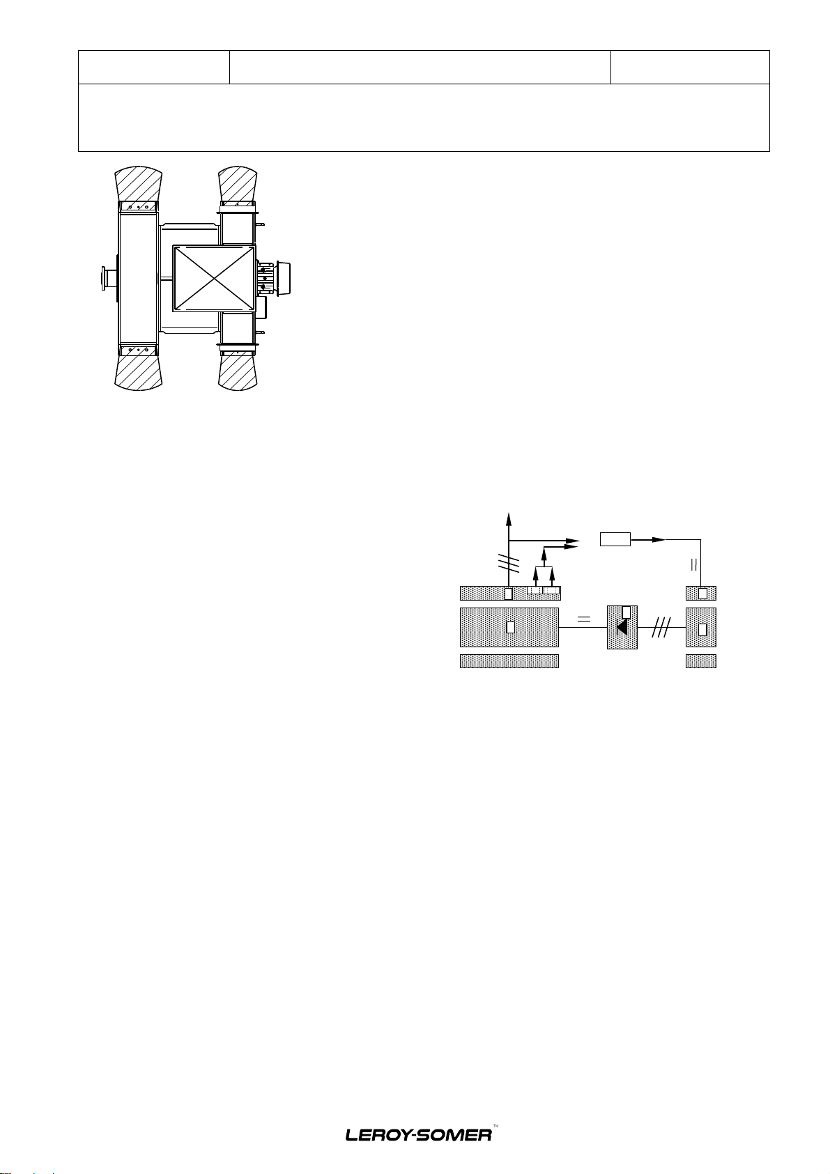
1.1.2.2 Vibratory analysis
It is the responsibility of the gen set manufacturer to ensure
that the different assembled system will be vibratory
compatible.(ISO 8528-9 and BS5000-3)
It is the responsibility of the gen set manufacturer to ensure
that the shaft line torsional analysis has been done and
accepted by the different parties (ISO 3046)
CAUTION :
EXCEEDING THE VIBRATORY LEVEL ALLOWED BY
THE STANDARD ISO 8528-9 & BS5000-3 MAY CREATE
HEAVY DAMAGES (BEARING DAMAGE, STRUCURE
CRACKS …).
EXCEEDING THE TORSIONAL VIBRATORY LEVEL OF
THE SHAFT LINE (ex: ABS, LLOYD …) MAY CREATE
HEAVY DAMAGES (CRANKSHAFT FAILURE ,
GENERATOR SHAFT FAILURE, …)
Refer to chapter 2.1.3.4 for further information about the
accepted vibration level of the standard ISO 8528-9 and
BS5000-3
1.1.2.3 Risk of blasting object
DANGER :
IN CASE OF MAJOR ACCIDENT, FLYING DEBRIS CAN
BE EJECT FROM THE MACHINE THROUGH THE AIR
INLET OR AIR OUTLET. THESE DEBRIS MAY CAUSE
INJURY OR LOSS OF LIFE. DO NOT ENTER INTO THE
HAZARDOUS AREA WHILE THE MACHINE IS
OPERATING
NOTE :
This risk has to be considered in the site risk
assessment.
Electric Power Generation Installation and maintenance 5654 en - 2017.10/ a
LSA 52.2 MHV
Industrial Range Alternators - 4 pole
4