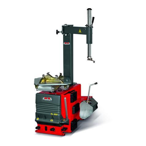
Nielsen CT2880 Operation instructions

TYRE CHANGER CT2880
ORIGINAI MANUAL
SAVE THESE INSTRUCTIONS FOR REFERENCE
Cannon Tools Limited
Address: 20 Station Road, Rowley Regis, West Midlands, B65 0JU.UNITED KINGDOM

EC DECLARATION OF CONFORMITY
We CANNON TOOLS LTD
20 Station road, Rowley Regis, West Midlands,B65 0JU.U.K.
Declare that the following machine complies with the appropriate basic safety and health
requirements of the EC Directive based on its design and type, as brought into circulation by
us.
In case of alteration of the machine, not agreed upon by us, this declaration will lose its validity.
Product description: TYRE CHANGER
Model: CT2880
Applicable EC Directives:
EC Machinery Directive 2006/42/EC
Harmonized standards
EN 60204-1:2018, EN ISO 12100:2010
20 Station Road, Rowley Regis, West Midlands, B65 0JU.U.K.
Mr. Gurcharan Tony Singh Sanghera
Managing Director
CANNON TOOLS LTD
2016-08-12

1. SPECIFICATION
Motor Power: 1.1kw (approx)
Power Supply: 230V / 50Hz
Max. Wheel Diameter: 45" (1140mm)
Max. Wheel Width: 14" ( 355mm)
Rim Clamping Form Outside: 12" - 23"( 300 - 580mm)
Rim Clamping Form Inside : 14" - 26"( 355 - 660mm)
Operating Pressure: 8-10 bar (approx)
Bead-Breaker Force: 2500kg
Noise Level: <70dB
Bead breaker force:14000 N
Dimensions: 2000 mm (H) x 1050mm(D) x 1100 mm(W)
Working temperature:-40℃-45℃
Transport/store temperature:-40℃-55℃
Humidity:30-95%
2. SAFETY INFORMATION
Read the instruction manual fully. Do not attempt any operation until you have read and
understood this manual. Most important you must know how to safely start and stop this
machine,especially in an emergency.
Keep the work area tidy and clean. Attempting to clear clutter from around the machine
during use will reduce your concentration. Mess on the floor creates a trip hazard. Any liquid
spilt on the floor could result in you slipping.
Find a suitable location. The location should provide good natural light or artificial lighting as
are placement. Avoid damp and dusty locations as it will have a negative effect on the
machine's performance.
Do not expose the machine to rain or any direct or indirect water spray. In all cases do not
operate power tools near any flammable materials.
Beware of electric shock. Avoid contact with earthed surfaces; because they can conduct
electricity if there is an electrical fault with the machine. Always protect the power cable and
route it away from danger.
Keep bystanders away. Children, onlookers and passers by must be restricted from entering
the work area for their own protection.The barrier must extend a suitable distance from the tool
user.
Do not overload or misuse the machine. All machines are designed for a purpose and are
limited to what they are capable of doing. Do not attempt to use the machine (or adapt it in

anyway) for an application it is not designed for.Select the machine appropriate for the size of
the job.Overloading the machine will result in its failure and user injury: This covers the use of
accessories.
Dress properly. Loose clothing, long hair and jewellery are all dangerous because they can
become entangled in moving machinery:This can also result in parts of body being pulled into
the machine. Clothing should be close fitted, with any long hair tired back and jewellery and
neck ties removed. Footwear must be fully enclosed and have a nonslip sole.
Wear personal protective equipment(PPE). Dust, noise, vibration and swarf can all be
dangerous if not suitably protected against. lf the work involving the power tool creates dust or
fumes; wear a dust mask.Vibration to the hand, caused by operating some tools for longer
periods must be protected against. Wear vibration reducing gloves and allow long breaks
between uses. Protect against dust and swarf by wearing approved safety goggles or a face
shield.These are some of the more common hazards and preventions; however,always find
out what hazards are associated with the machine/work process and wear the most suitable
protective equipment available.
Move the machine as instructed.Always refer to the instructions for the correct method.
Do not overreach.Extending your body too far can result in a loss of balance and you
falling.This could be from a height or onto a machine and will result in injury.
Maintain your tools correctly. A well maintained tool will do the job safely.Replace any
damaged or missing parts immediately with original parts from the manufacturer.As
applicable;keep blades sharp; moving parts clean, oiled or greased; handles clean; and
emergency devices working.
Wait for the machine to stop. Unless the machine is fitted with a safety brake; some parts
may continue to move due to momentum. Wait for all parts to stop; then unplug it from the
power supply before making any adjustments, carrying out maintenance operations or just
finishing using the tool.
Remove and check setting tools.Some machinery requires the use of additional tools or
keys to set, load or adjust the power tool Before starting the power tool always check to make
certain they have been removed and are safely away from the machine.
Prevent unintentional starting. Before plugging any machine in to the power supply, make
sure the switch is in the OFF position. If the machine is portable; do not hold the machine near
the switch and take care when putting the machine down; that nothing can operate the switch.
This machine is not suitable for use with an extension lead.
Concentrate and stay alert. Distractions are likely to cause an accident. Never operate the
machine if you are under the influence of drugs (prescription or otherwise), including alcohol or
if you are feeling tired.Being disorientated will result in an accident.
Have this machine repaired by a qualified person. This machine is designed to conform to
the relevant international and local standards and as such should be maintained and repaired
by someone qualified; using only original parts supplied by the manufacturer:This will ensure
the machine remains safe to use.

SPECIFIC SAFETY INSTRUCTIONS FOR TYRE CHANGER USE
. Make sure this machine is used on a dry, flat, level, oil/grease free, concrete surface capable
of supporting the weight of the tyre changer, any additional tools, equipment and wheel tyre
combination.
. Before each use, always examine the tyre changer for structural cracks and bends, damage
to the safety guard, electrical wiring, and any other condition that may affect the safe operation
of the machine. Do not use the tyre changer even if minor damage is apparent.
. Maintain a safe working environment. Keep the work area well lit. Make sure there is
adequate surrounding workspace.Always keep the work area free of obstructions, grease, oil,
and other debris. Do not use the tyre changer in a damp or wet location. Do not use the tyre
changer in areas near flammable chemicals, dusts, and vapours.
. This tyre changer is designed for use with most passenger car and light commercial vehicle
wheels. Do not attempt to exceed this machine's maximum wheel diameter capacity.
. Always keep hands, fingers, and feet away from the moving parts of the tyre changer while
the machine is in use.
. Never leave the tyre changer unattended when it is running.After completing a tyre changer
job, always turn the Power Switch to its “OFF” position, and wait until the machine comes to a
complete stop before leaving.
. Make sure you read and understand all instructions and safety precautions as outlined in the
manufacturer’s manual for the wheel you are balancing, and the vehicle the wheel is to be
used on.
. Always unplug the tyre changer from its electrical supply source before performing any
inspection, maintenance, or cleaning procedures.
.WARNING: People with pacemakers should consult their physician(s) before using this
product.Operation of electrical equipment in close proximity to a heart pacemaker could cause
interference or failure of the pacemaker.

3. TECHINAL DESCRIPTION
Fig.1
No
Item
No
Item
No.
Item
No
Item
A
Tilting pedal
G
Bead breaker
shovel
M
Return spring
S
Clamping
cylinder
assembly
B
Jaw flex pedal
H
Bead breaker
arm
N
Locking handle
T
Barometer
C
Bead breaker pedal
I
Hanger
O
Mount/demount
head
U
Frame
D
Turntable control
pedal
J
column base
P
Turntable
V
Side cover
E
Tire lever
K
Post
Q
Clamping jaw
W
Inflating pedal
F
Rubber buffer
L
Arm
R
Slide
X
Sign board
Accessories provided
are
shown in Fig.2:
1-
Inflator hose
2-
Tyre lever
3-
clamping jaw protector
Fig.2

4. UNPACKING
Carefully remove the product from the packaging and examine it for any sign of damage that
may have happened during shipping. Lay the contents out and check them against the parts
shown below. If any part is damaged or missing; please contact the seller and do not attempt
to use the product.
Keep the packing materials out of the reach of children. Handle in an appropriate way if the
packing material is likely to cause pollution.
Remove the cabinet, column, swing arm and accessory box fitted on the bottom plate and
keep them in safety place.
5. INSTALLATION AND ADJUSTING
The place to install the machine should be in
accordance with safety regulations:
•The machine should be installed in a place
close to the main power source and
compressed air system.
•Install the machine on smooth concrete ground
or other ground with hard flooring. 4 sets of
anchor bolts M10X150 can be used to fasten
the machine onto the ground to avoid vibration
and noise.
•Leave enough space for the operation and
maintenance of the machine. The space should
be no less than 1M in front and on the two sides
of the machine, 0.5M behind it so that operation
on different parts shall not be hindered.
•If the machine has to be installed outdoors,
a protective shelter should be built.
•Never operate the machine in a place with
flammable gas.
NOTE: For safety and proper operation,
keep the machine at least 0.5M away
from any wall.
Installation
Move the column C and arm D, put
them on a soft cushion.(Fig.4)
Caution:
When you lift the column, the arm D will
fall freely, be careful!
Fig.3
Fig.4

1. Install return spring
As Fig.5, Remove screw M10*30 H with
Allen key, take out B and return spring
A. Install column E as direction marked,
install return spring A and B, fasten H.
NOTE:Pay special attention the direction
of mounting head F.
2. Install post
As. Fig.6,Use 6mm inner hexagon spanner
to take off four pieces screw B and washer C,
then take off the side cover A and cover D as fig.6.
Lift column E as fig.6 , make the pin hole of column
and body in line, insert pin axis H, tighten screw F
and washer G (screw M12x25)(If column can not be
fixed in, loose screw M, after installation finished,
tighten screw M again.).
Tilt column, make hose O (φ4) and P(φ8) through
hole N in the body (Fig. 7).
NOTE:Make sure hose O(φ4) and P(φ8) begin
at the back of pin L to avoid hose damaged.
Lift cylinder rod I at maximal and adjust the direction
of column E as Fig.7, make pin hole of column J
direction and cylinder rod I direction in line, insert pin
axis J, tighten screw K. (screw M12x55, M12).
Let column stand up, finish column installation.
Connect hose in the column:
As fig.7-b,connect φ4 hose O to regulator Z,
φ8 hose P to pedal X.
NOTE:
When the machines come out factory, the
regulator Z has already been adjusted pressure
(4 bar), please do not adjust it by yourself.
Fig.7-b
Fig.7-a
Fig.6
Fig.5

3. Install Hanger
•As fig.8 Insert the two heads into two φ5
Holes in the right side of column, make
sure R heads, hook is upward.
•Install side cover A and cover D, fasten
With screws as Fig. 6
4. Lifting and installation
Take off two pieces of screws by spanner
(Fig. 9). Use hoist to lift the machine, move
pallet, locate the machine.
Power and Air Connections and Regulator
•Before installation, check if the power source
and the compressed air are in accordance with
the specifications on the nameplate. Any
electrical connection should be done by the
specially trained technician.
•The power socket should be at a place within
the sight of the operator. The height should be
between 24”~67”.
•Grounding protection of power is needed for
machine shell.
•Air connection:Connect the inflation gun A to
Barometer (Fig.10) .
•Connect the compressed air supply to the coupling
located between the lubricator and the air filter S
(as fig.10, direction of arrow).
Fig.8
Fig.9
Fig.10

NOTE:The tire changer is not equipped with overload protection. Please connect power
according to the electric diagram included in the User’s manual. Otherwise, the manufacturer
will not be responsible for any accidents.
•Operation test: after power connected, press
pedal D (Fig.11), turntable will turn clockwise.
This test is very important.
•F.R.L. :Filter, Regulator, Lubricator Assembly
(optional):
◆See Fig. 12:
1- Lubricator;2- Filter;3- Regulator
◆Adjust pressure: There is a button for the regulator
When pulled up, the pressure can be increased
or decreased by turn it clockwise or counter-clockwise
(check the 4-Gauge). After adjusting the operation
pressure, press the button down to lock it
The Filter 2 works to filter the water and impurity
in the compressed air. When water and impurities
run beyond the red line, turn open the ejection valve
5 to release them.
◆The lubricator 1 is used to add a certain amount
of lubricant into gas for the moving parts in the cylinder
and regulator. Depress pedal C, 3~5 times,
a drop of lubricant will drop into the cup in the regulator.
If it doesn’t happen, the adjusting screw 6 can be
adjusted.
Fig.11
Fig.12
3
4
1
2
5
6

6. OPERATION
NOTE:Do not operate the machine before having completing training and qualified for
operating the tire changer. Use appropriate equipment, tools and personal protective
equipment, such as eye-glasses, ear-plugs and working boots, when operating the tire
changer.
Make sure that the power, air sources and the oil level in the oil cup are in accordance with the
requirements.
Principles
•To avoid damage when mounting and demounting tire, especially the alloy ones, use the
specialtire lever.
•For easier demounting and better protection of the tire and rim, lubricate the area between
the rim and tire bead, where the bead breaker shoe goes in, with industrial lubricant or thick
soap solution.
•Pay special attention to rotary direction marked on some flanges or tires.
•Fit the tire on the rim of matched size.
•Check for damages (distortions, surface damages, excessive run out, erosion or overall
wear) before demounting.
•Never ignore the mounting and demounting requirements of the special wheel.
•When inflating the tire, make sure the pressure increases in an even way. Check the rim as
often as possible.
Demounting Tyre
1. Preparing
•Deflate the tire thoroughly.
•Remove all the foreign substance and
weights from the rim (Fig. 13).
2. Demounting
NOTE:Lubricate the bead with a brush with
lubricant before the shoe touches the bead.
•Otherwise the tire bead will be worn (Fig.14)
Place the tire between the bead breaker shoe
and rubber pad and keep the shoe between the
bead and rim, about 1cm to the bead (Fig.15-a).
Depress pedal C (Fig.15-b) to separate the tire
from rim.
Fig.13
Fig.14

•Repeat the above steps on other part of the tire
to get the tire separated thoroughly from the rim.
•Bead breaker can be adjustable for different
width tire, pull out handle Z and let the moveable
part go to its right position, then insert handle Z back.
NOTE:When using the bead breaking arm, do
not put arms and hands between the tire and the
bead breaker.
•Press switch handle button N (Fig. 16), fix arm.
•Press pedal A, tilt the column.
•Depress pedal B, Place the wheel on the turntable,
and lock rim(Fig. 17).
NOTE:Different types of clamping can be chosen
in accordance with different rims.
•In case of inward clamping, shrink the jaws together,
place the wheel on the turntable and depress pedal B
to clamp (Fig.18-a).
•In case of outward clamping, enlarge the jaws outward
(2-3cm away from periphery of the rim) and place the
wheel on the turntable. And depress pedal B to clamp
it(as fig.18-b).
•Press pedal A (Fig.16), let column back to its working position, pull back switch handle N (Fig.
19-a), let the arm L and hex column M move freely. Push N and press M, make mounting head
O against rim (Fig. 19-b), press switch handle N lock arm and hex column. Make sure
mounting head keep a distance of 1~2mm from upper edge of rim and 2mm from outer edge
Fig.15
Fig.16
Fig.17
Fig.18

of rim to avoid mounting head scratch rim
•Insert lever into wheel near mounting head (Fig. 20).
•Press lever as Fig. 20-2 and press wheel as fig. 20-1, until upper edge of wheel as Fig. 21,
press lever slowly, until upper edge of wheel hang on the mounting head.
Note: If there is inner tube inside, keep the position of air inlet valve and mounting head at
distance of 10cm. as Fig. 22.
•Press pedal D (Fig. 20), turntable turn clockwise, until edge of wheel fall off.
Note: For very tough and low profile wheel, wheel edge is easy to slip off, to avoid this, before
turn clockwise of the turntable, may turn anti-clockwise a little to make the turntable back
1-2mm.
•If the demounting process is prevented, stop the turntable from turning around, lift pedal D
(Fig. 20), let the turntable turn anti-clockwise.
Fig.20
Fig.19
Fig.22
Fig.21

•If there is tube in the tire, remove it.
•Lift wheel, make the bottom edge of wheel
onto mounting head as Fig. 23.
•Press pedal D until bottom edge of wheel fall off.
•Depress pedal A, tilt column, take off wheel,
and finish demounting.
Caution:
Keep hands and the rest of human body away from
the moving parts of the machine. Never wear
necklace, bracelet or loose clothes when operating
the machine as it may cause danger!
Mounting Tire
Note: Check the size of tire and rim to see if they match each other.
•Clamp the rim tightly in the same way as demounting tire.
•Use lubricant such as thick soap solution on the tire and the rim.
•Put the bead on the rim with the left side upward, press pedal A to make column back to its
working position (Fig.24).
•Check the coordination of mount/demount head and rim. Readjust if necessary.
•Adjust relative position between the tire and the mount/demount head to make the tire
bead cross the mount/demount head. At the end of the mount/demount head, the tire bead
should be placed on the mount/demount head (Fig.25-A). At the beginning of the
mount/demount head, the tire bead should be placed under the ball protuberance of the
mount/demount head (Fig.25-B).
•Press down the central part of the tire. Depress the pedal D (Fig.20) to turn the turntable
clockwise, making the lower tire bead fall into the rim groove completely.
Fig.23
Fig.24
Fig.25

•If a tube needs to be installed in the tire, check first for the possible damages. Round it onto
the rim. Make sure to keep the tube in the right position throughout the mounting process.
•To install the upper tire bead, place the tire well and readjust position of the tire bead
(same as mount of the lower tire bead in Fig.26-B. Press down the tire opposite to the
mount/demount head to the rim groove (Fig.27)
•Depress the pedal D (Fig.20) to turn the turntable while keeping pressing on the tire. When
only 10~15cm is left, slow down to avoid damage of the tire bead. Stop the motor if there is
any indication for damage. Lift the pedal D and turn the turntable counter-clockwise. Try again
when the tire is back to the original shape.
Note: It is not necessary to move the handle of the screw every time if the size of rim matches
the tire. Just move the arm.
In the process of operation, keep head and hands away from the area between the tire and the
swing arm to avoid injury.
Inflating Tire
Danger!!Inflating can be highly dangerous. Take precautions and pay close attention to the
procedures. Check if the compressed air is well connected before inflating.
Inflating procedures are shown in Fig.28. The
machine is equipped with a gauge to read the
pressure in the tire.
•Connect the outlet of the gun to the air
inflation valve
•Slowly press the switch on the inflating gun
for several times during inflation to make sure
that the reading on pressure gauge meets the
manufacturer’s specifications. The pressure
should not exceed 3.5 bar.
•If the pressure exceeds the limit, press the button on the gun inflator so that the pressure
goes down to what is required.
Fig.28
Fig.26
Fig.27

Danger!Danger of explosion!
The safety procedures should be closely followed. Review and abide by the following
instructions. Otherwise serious injury or death can be resulted. The manufacturer shall not be
held responsible for any possible accident when the safety procedures are not followed.
◆Carefully check the dimensions of rim and tire to see if they match each other. Check and
make sure that the tire is not worn or damaged before inflation.
◆When a high pressure is required, remove the tire from the tire changer and resume the
inflation in a special protective hood.
◆Be careful when inflating the tire. Keep hands and the rest of human body away from tire.
◆The operator must adopt all the measures necessary in order to guarantee safe conditions.
7. TROUBLE SHOOTING
Malfunction
Cause
Solution
The chuck does not
rotate in any direction.
1. Power plug not inserted.
2. Incorrect connection in
the plug.
3. Electrical supply not
suitable.
Check correct plugging and
its
connection.(see cause 2 and 3)
Pressing the invertor
pedal down causes the
chuck to turn in an
anti-clockwise
direction.
Polarity inverted.
Invert the connections in the power plug
The chuck turns with
1.Supply voltage wrong.
1. Check the correspondence
between the supply voltage and that
on the maker’s plate.
2. Tighten the belt.
insufficient power.
2.Driving belt loosen.
The bead breaker
does not have
sufficient power to
break the tire bead.
1.The pneumatic supply is
not connected to
the machine.
2.Insufficient pressure in
the pneumatic system.
3.Pressure reducer is
closed or badly adjusted
(for versions with this
device).
1.Connect the pneumatic supply.
2.Correct the supply pressure.
3.Open or correctly adjust the
pressure reducer.

8. MAINTENANCE
Note: Only the specialized technician can do the maintenance. Before any maintenance is
performed, disconnect the power and keep the plug within the sight of the maintenance
personnel. and shut off compressed air, push the air valve switch to “Off” position and depress
pedal 16 for 3 or 4 times to bleed the residual compressed air in the machine.
To keep the tire change in good condition and to prolong the work life, it is necessary to do
regular maintenance according to the instructions on the user’s manual. Otherwise, the normal
operation and reliability of the machine will be affected, or personal injury would be caused.
•Keep the machine and working area clean and prevent dust or foreign matter from entering
the moving parts.
•Keep the quadrate column and the moving parts clean and lubricate (clean with diesel as in
Fig.29-1 & 2 & 3 )
•Keep the swing arm clean and lubricate it periodically so that it can moveexpectably.
•Weekly lubricate the faying surface between moving parts and rubbing surface with lithium
lubricant.
•Check the oil level in the sprayer regularly. If the oil level does not reach the second line, fill
hydraulic oil L-HM46 (Fig. 30).
•Clear away the condensed material in the water separator around the sprayerregularly.
•Regularly check and adjust the tension of the belt.
•Check all connecting parts and bolts regularly and tighten them ifnecessary.
•Check and adjust locker handle periodically, to make sure after locking, mount head and
rim keep 2-3m distance.
Fig.29
Fig.30

9. STORING AND SCRAPPING
Storing
When the equipment needs to be stored for a long time:
•Disconnect the power and compressed air.
•Lubricate all the parts: slide block and groove.
•Empty all the oil/liquid cups.
•Cover the equipment with plastic shield.
Scrapping
When the equipment can no longer be used, disconnect the power and compressed air and
dispose in accordance with the local regulations.
10. DISPOSAL
At the end of the machine's working life, or when it can no longer be repaired, ensure that it is
disposed of according to national regulations.
Contact your local authority for details of collection schemes in your area.
In all circumstances:
Do not dispose of this tool with domestic waste.
Do not incinerate.
11. EXPLANATION OF SYMBOLS
The following symbols are used in this manual and/or on the machine:
Denotes risk of personal
injury or damage to the tool
WARNING – To
reduce the risk of
injury, user must read
instruction manual”
In accordance with essential
safety standards of
applicable European
directives
Mandatory use of eye
protection
Wear ear protection
Wear a dust mask
Wear safety gloves
Always wear appropriate
clothing
When operating this
machine.

12. SPARE PARTS LIST
No.
Code
Description
Qty
No.
Code
Description
Qty
2065618 Parts of Column & Arm (Fig. 31)
101
2065619
Column
1
146
2065643
Rubber block plate
1
102
3005009
Union IPL 4-01
1
147
6000191
Screw M8*30
1
103
6000120
Screw M6*30
4
150
2065668
Tilting cylinder
1
104
2065640
Screw M10*25
2
151
2039701
cylinder rear cover
1
105
6000123
Screw M10
2
152
6000148
Screw M8
8
106
2065638
Locking plate
1
153
6000139
Washer Ф8
8
107
6000126
Screw M12
2
154
3005043
O-seal82×2.6
2
108
2065640
Screw M12*60
2
155
2023701
Cylinder rod
4
109
2065639
Spring
2
156
2023501
Cylinder
1
112
2038801
Bearing
2
157
6000242
Screw M12
1
113
2064379
Bearing pin
1
158
6000135
Washer Ф12
1
114
2065642
Roller seat
1
159
2039801
Piston
1
115
6000335
Screw M8*25
2
160
3001001
Y seal 20×36×8
1
116
6000127
Screw M8
2
161
2039601
cylinder front cover
1
117
6000139
Washer 8
2
162
2065537
Piston rod
1
118
6000103
Screw M8*16
2
163
3005011
Union ISC8-01
2
119
6000424
Screw M12*55
1
165
1011817
Barometer
1
120
6000144
Screw M12
1
166
2064871
Barometer box
1
121
3005274
Protective heel
2
167
6000341
Screw M4
1
122
6000244
Screw M8*20
1
168
6000268
Screw M4*16
1
123
2065644
Washer
1
169
3005002
Union IPB8-02
1
124
2065630
Arm
1
170
2064873
Valve body
1
125
3004201
Sleeve
1
171
2064874
Valve bush
1
126
2045101
Spring
2
172
2064875
Valve handle
1
127
2064804
Locking plate
1
173
3005198
O seal 8(outer)*1.8
1
128
3005039
Cover
1
174
2064876
valve rod knob
1
129
6000138
Washer 6
1
175
2064877
Spring
1
130
6000114
Screw M6*20
3
176
6000393
Screw M4*8
3
131
6000347
Screw M5*12
1
177
4004386
Barometer
1
132
6000143
Screw M10
1
178
3005079
Union IPLF8-02
1
133
6000134
Washer 10
1
180
2039001
Mount /demount
head
1
134
3005001
Union IPB 4-01
1
181
2039101
Mount /demount
head
1
135
2021301
Locking valve
1
182
3004001
Washer
1
136
6000119
Screw M5*12
4
183
3004201
Mount/demount
head protector
1
137
6000121
Screw M8x30
1
184
2004801
Roller pin
1
138
6000387
Screw M10x30
1
185
2004701
Roller
1
139
3005190
Knob
1
186
6000334
Screw M10×10
2
140
2037701
Spring
1
187
6000225
Screw M10×16
2

141
2064803
Column
1
190
2039201
Locking cylinder
2
142
3005188
Washer
1
191
2021201
Cylinder cover
1
143
2052501
Washer
φ34*10*5
1
192
3005191
O seal
1
144
6000184
Washer
M10*25
1
193
3004101
Cylinder
1
145
3005275
Rubber block
1
2065661 Parts of Turning Table Assembly
(
Fig.32
)
201
2064878
Turn Table
1
219
2064880
Slide support
2
202
6000129
Screw M16*40
1
220
2017801
Complete cylinder
2
203
2065256
Gland
1
221
2018001
Cylinder axis
1
204
6000232
Pin
8
222
3005074
Union IPL6-01
1
205
2017101
Jaw
4
223
2045801
Cylinder front cover
1
206
2064923
Slide
4
224
3004701
O-seal 68.3*3.5
2
207
2064885
Slide plank
4
225
2018101
Cylinder rod
4
208
2064883
Cylinder
support
2
226
3005157
Y-seal
1
209
6000236
Retaining ring
12
4
227
2064398
Brushing
1
210
6000135
Washer
12*20*2
4
228
3005250
O-seal 75*5.7
2
211
2017201
Connecting rod
4
229
3005249
O-seal 16*24
1
212
2053201
Connecting rod
ring
4
230
2012001
Piston
1
213
6000135
Washer
12*20*2
4
231
6000144
Screw M12
1
214
6000213
Washer 12
4
232
2017901
Cylinder
1
215
6000260
Screw M12*75
4
233
2045901
Cylinder rear cover
1
216
6000212
Screw M12*30
4
234
3005075
Union IPB6-01
1
217
6000196
Retaining ring
70
1
235
6000308
Screw M5
8
218
2016801
Turn plate
1
2053301 Parts of Rotating Valve Assembly(Fig.33)
300
2053301
Complete
rotating valve
1
303
3004601
O-seal 59.5*3.1
3
301
2010901
Rotating valve
core
1
304
2011001
Rotating valve
casing
1
302
3005004
Union IPC6-01
4
305
6000356
Screw M3*5
4
Table of contents
Popular Tyre Changer manuals by other brands
CEMB
CEMB SM825 manual

Branick Industries, Inc.
Branick Industries, Inc. 5500 Installation, Operation and Repair Parts Information

Bosch
Bosch TCE 4540 Original instructions
Launch
Launch TWC-401NIC Operation manual
Hunter
Hunter TCX50H Series Operation manual

Fasep
Fasep RGU588E Installation, use and maintenance guide

