CEMB SM825 User manual

REV. 01 1 / 28
SM825 ver.T
Semi-Automatic Car
Tire Changer Manual

REV. 01
2 / 28
PRINTING CHARACTERS AND SYMBOLS
Throughout this m nu l, the following symbols nd printing ch r cters re used to f cilit te re ding:
Indic tes the oper tions which need proper c re
Indic tes prohibition
Indic tes possibility of d nger for the oper tors
BOLD TYPE
Import nt inform tion
WARNING: befo e ope ating the lift and ca ying out any adjustment, ead
ca efully chapte 7 “installation” whe e all p ope ope ations fo a bette
functioning of the lift a e shown.

REV. 01
3 / 28
CONTENTS
1 INTRODUCTION 4
2 GENERAL INFORMATION 6
3 TRANSPORT, UNPACKING AND STORAGE 9
4 INSTALLATION 10
5 OPERATION 16
6 INFLATING 20
7 MAINTENANCE 22
8 TROUBLESHOOTING 24
9 ELECTRIC AND PNEUMATIC DIAGRAM 25

REV. 01
4 / 28
CHAPTER 1 – INTRODUCTION
1.1 INTRODUCTION
Th nk you for purch sing product from the line of tire ch ngers. The m chine h s been
m nuf ctured in ccord nce with the very best qu lity principles. Follow the simple instructions
provided in this m nu l to ensure the correct oper tion nd long life of the m chine. Re d the entire
m nu l thoroughly nd m ke sure you underst nd it.
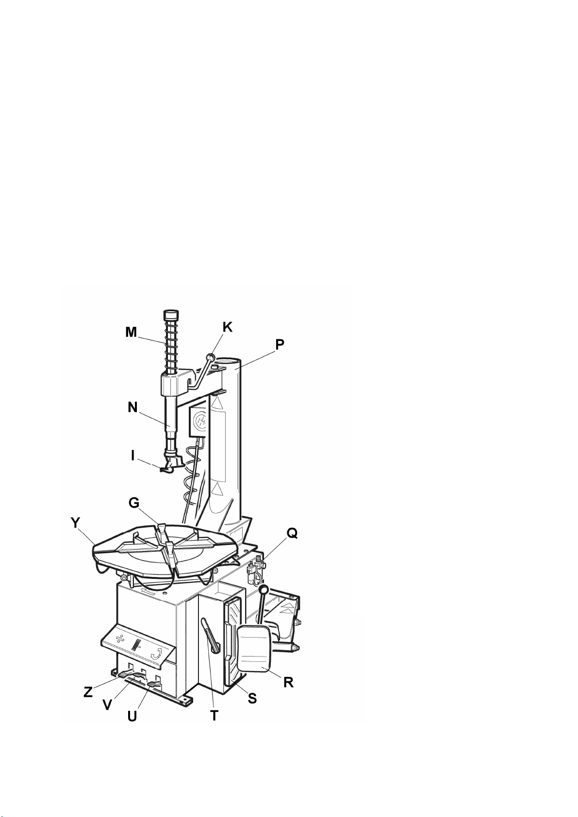
1.2 TYRE CHANGER IDENTIFICATION DATA
A complete description of the “Tire Ch nger Model” nd the “Seri l number” will m ke it e sier for
our technic l ssist nce to provide service nd will f cilit te delivery of ny required sp re p rts. For
cl rity nd convenience, we h ve inserted the d t of your tire ch nger in the box below. If there is
ny discrep ncy between the d t provided in this m nu l nd th t shown on the pl te fixed to the tire
ch nger, the l tter should be t ken s correct.
1.3 MANUAL KEEPING
For proper use of this m nu l, the following is recommended:
• Keep the m nu l ne r the lift, in n e sily ccessible pl ce.
• Keep the m nu l in n re protected from the d mp.
• Use this m nu l properly without d m ging it.
• Any use of the m chine m de by oper tors who re not f mili r with the instructions nd
procedures cont ined herein sh ll be forbidden.
This m nu l is n integr l p rt of the m nu l: it sh ll be given to the new owner if nd when the
m chine is resold.
The illust ations have been made out of p ototypes pictu es. It is the efo e
possible that some pa ts o components of standa d p oduction diffe f om those
ep esented in the pictu es.
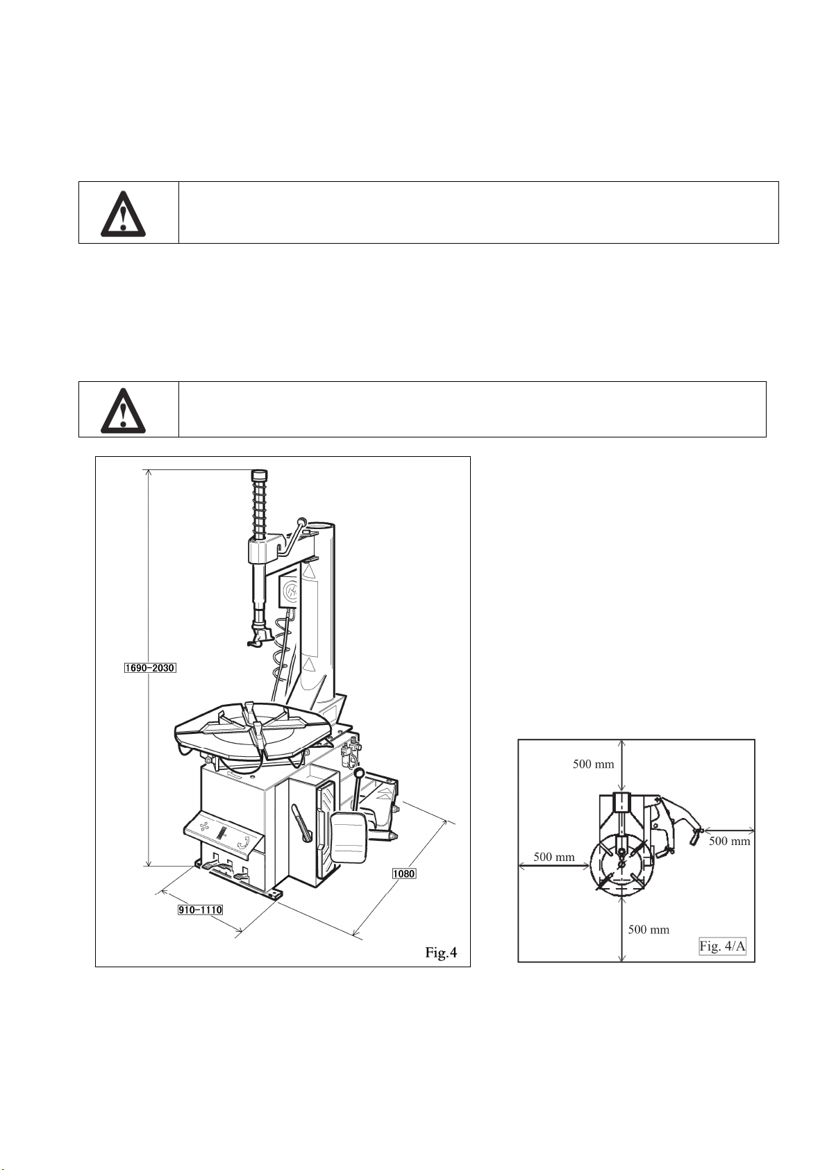
1.4 GENERAL SAFETY PRECAUTIONS
The ti e change may only be used by specially t ained and autho ized expe t
pe sonnel.
LOGO
Type:
Volt Amp Kw
Ph Hz
Ye r of m nuf cturing:
Air supply: 8-10 b r (116 – 145 PSI)

REV. 01
5 / 28
• Any t mpering or modific tion to the equipment c rried out without the m nuf cturer’s prior
uthoriz tion will free him from ll responsibility for d m ge c used directly or indirectly by
the bove ctions.
• Removing or t mpering with s fety devices immedi tely inv lid tes the gu r ntee.
• The tire ch nger comes complete with instruction nd w rning tr nsfers which re designed
to be long-l sting. If they should for ny re son be d m ged or destroyed, ple se sk
immedi tely for repl cements from the m nuf cturer.
TO THE READER
Every effort h s been m de to ensure th t the inform tion cont ined in this m nu l is correct, complete
nd up-to d te. The m nuf cturer is not li ble for ny mist kes m de when dr wing up this m nu l nd
reserves the right to m ke ny ch nges due the development of the product, t ny time

REV. 01
6 / 28
CHAPTER 2 – GENERAL INFORMATION
2.1
INTENDED USE
• This Semi- utom tic tire ch nger h s been designed nd m nuf ctured exclusively for
removing nd mounting tires from/onto rims from 10" to 26" nd m ximum di meter of
1000 mm.
• In p rticul r THE MANUFACTURER c nnot be held responsible for ny d m ge c used
through the use of this tire ch nger for purposes other th n those specified in this m nu l, nd
therefore in ppropri te, incorrect nd unre son ble.
2.2 DESCRIPTION
G) Cl mps
I) Mounting he d
M) Mounting b r
N) Horizont l rm
P) Vertic l rm
Q) Air supply
R) Be d bre ker
S) Wheel support
T) Be d lifting lever
U) Cl mp control ped l
V) Cl mp control ped l
Z) Reverser control ped l
Y) Turnt ble
K) Locking lever
Fig . 1

REV. 01
7 / 28
2.3 DANGER WARNING SIGNS

REV. 01
8 / 28
2.4 TECHNICAL SPECIFICATION
Extern l locking rim dimension
12" - 26"
13" - 27"
14" - 28"
Intern l locking rim dimension
14" – 28”
15" - 29"
16" - 30"
M x. tire di meter 1200mm (47.5”)
M x tire width 470mm (18.5”)
Force on be d bre ker bl de (10 b r) 2500 kg
Working pressure 8 b r (116 psi)
Infl ting pressure device m x. 3.5 b r (50 psi)
Power supply volt ge
400V 3 Ph
230V 1Ph
110V 1PH
Motor power
0.55 (400V 3 ph single speed)
0.8/1.1 kw (400V 3ph double speed)
0.75 kw (230V 1ph)
1.1KW (110V 1ph)
Rot ting speed 7 – 14 rpm
M x spindle torch 1200 NM
Dimension 1140 x 1100 x 950
Net weight 240 kg STND
Noise level in working condition < 70 dB (A)

REV. 01
9 / 28
CHAPTER 3 – TRANSPORTATION, UNPACKING AND STORAGE
3.1 TRANSPORTATION
• The tire ch nger must be tr nsported in its origin l p ck ging nd kept in the position shown
on the p ck ge itself.
• The p ck ged m chine m y be moved by me ns of fork lift truck of suit ble c p city. Insert
the forks t the points shown in figure 3.
3.2 UNPACKING
• Remove the protective c rdbo rd nd the nylon b g.
• Check th t the equipment is in perfect condition, m king sure th t no p rts re d m ged or
missing. Use fig. 1 for reference.
If in doubt do not use the machine and contact you etaile .
3.3 STORAGE
In the event of stor ge for long periods of time, be sure to disconnect ll sources of power nd gre se
the cl mp sliding guides on the turnt ble to prevent them from oxidizing.

REV. 01
10 / 28
CHAPTER 4 – INSTALLATION
4.1 SPACE REQUIRED
When choosing the place of installation be su e that it complies with cu ent safety
at wo k egulations.
• The tire ch nger must be connected to the m in electric power supply nd the compressed ir
system. It is therefore dvis ble to inst ll the m chine ne r these power sources.
• The pl ce of inst ll tion must lso provide t le st the sp ce shown in pictures 4 - 4/A so s to
llow ll p rts of the m chine to oper te correctly nd without ny restriction.
• If the m chine is inst lled outside it must be protected by le n-to.
The ti e change with elect ic moto cannot be used in explosive atmosphe es,
unless it is a p ope ve sion.

REV. 01
11 / 28
4.2 POSITIONING AND PARTS ASSEMBLY
• Unscrew the p llet fixing screws nd set the tire ch nger on the floor.
• Unscrew the 4 screws from the body, set the vertic l rm into the proper se t nd fix the screw
g in (Fig. 5/ ).
• M ke sure the horizont l rm is on the vertic l rm’s support nd the pin is locked with nuts
nd w shers s shown in Fig. 5/b.
Befo e connecting all the powe sou ces ALWAYS check you installations.
They must exactly co espond to those equested by the machine.
• Connect the m chine to the compressed ir network (Fig. 5/d)
• Mount the be d bre ker rm s shown in Fig. 5/e:
- Set the rm “ ” into the proper se t, set the screw into the hole nd screw the nut
WITHOUT TIGHTENING.
- Set the pivot pin “b” into the hole on the rm nd let the cylinder’s sh ft p ss through
the pin’s hole. Screw two nuts WITHOUT TIGHTENING.
- Set the spring by hooking it t the indic ted points.
• Screw the be d bre ker rm’s screw s indic ted in Fig 5/f
• Screw the nut s indic ted in Fig 5/g

REV. 01
12 / 28

REV. 01
13 / 28
4.2.2 Mounting and connecting the GT
• Route the tube (1), situ ted inside the
m chine body, though the hole on the b ck
side of the body.
• Connect the hose (4) to the connectors (2)
using the b nds (3).
4.2.3 Mounting and connecting the manomete
• Fix the m nometer to the vertic l rm
through the proper screw. Fig. 11.
• Route the connecting spir l hose through the
sm ll hole on the b ck side of the m chine
body.
• Connect the rils n hose to the union of the
pressure limiting device, situ ted on the
infl ting ped l.

REV. 01
14 / 28
4.3 COMMISSIONING
Any elect ic connection job must be ca ied out by p ofessionally qualified
pe sonnel.
Make su e that the powe supply is ight.
Make su e the connection of the phases is ight. Imp ope elect ical hook-up
can damage moto and will not be cove ed unde wa anty.
• Check to m ke sure the ch r cteristics of your systems correspond to those required by the
m chine. If you h ve to ch nge the m chine’s oper ting volt ge, m ke the necess ry
djustments to the termin l bo rd referring to the electric di gr m in ch pter 9.
• Connect the m chine to the compressed ir system by me ns of the ir connection (Q) th t
protrudes from the re r section.
Connect the machine to the elect ic netwo k, which must be p ovided with
line
fuses, a good ea th plate in compliance with egulations in fo ce and it must
be
connected to an automatic ci cuit b eake (diffe ential) set at 30 mA.
Should the ti e-change be lacking in elect ic plug, the use must set one, which
is at least 16 A and which confo ms to the voltage of the machine, in compliance
with the egulations in fo ce.
4.4 OPERATING TESTS
• When ped l (Z) is pressed down the turnt ble (Y) should turn in clockwise direction. When
ped l is pulled up the turnt ble should turn in n nticlockwise direction.
If the tu ntable tu ns in the opposite di ection to that shown, eve se two of the
wi es in the t ee-phase plug.
• Pressing the ped l (U) ctiv tes the be d
bre ker (R); when the ped l is rele sed the
be d bre ker returns to its origin l position.
• Pressing the ped l (V) opens the four cl mps
(G); when the ped l is pressed g in they
close.
• Pressing the trigger on the irline g uge c use
ir to be rele sed from the he d.

REV. 01
15 / 28
4.4.1 GT ve sion
Do NOT LEAN on the tu ntable du ing this ope ation. Possibly di ty dust on
tu ntable could offend the ope ato ’s eyes. Fo the same eason, be ca efully as
not to accidentally push the inflating pedal while wo king.
• When the ped l loc ted on the left side of the m chine
body is pushed down to its intermedi te position (B),
ir is rele sed from the irline g uge.
• When the ped l (C) is pushed down completely, ir is
rele sed from the irline g uge with powerful jet from
the nozzles loc ted on the turnt ble cl mps.
4.5 TURNTABLE LOCKING VALUE ADJUSTING
The tire ch nger turnt ble is preset by the m nuf cturer on middle r nge me sure from12” to 28”
ext. (considering the rim outer side nd) from 14” – 30” int. (if you lock the rim from inner side).
It is however possible to ch nge this dimension r nge in c se of need when working on l rger or
sm ll rims; it is enough to ch nge the position of the 4 cl mps re shown in the figures below.
The obt in ble v lue st rts from minimum of 12”-26” ext. nd 14”-28” int. until m ximum of 14”-
28” ext. nd 16”-30” int.
To ch nge the position, proceed s follows:
• Unscrew screw (1) by me ns of the Allen wrench.
• Remove the locking cl mp (2) nd the slide piece (3).
• Align the slide hole with one of the guide holes (4) ccording to the locking dimensions you
w nt to set. Use the me sures below for reference.
It is impo tant to pe fo m the above mentioned ope ation fo all the 4 clamps to
avoid any unbalance in locking phase.
Fig. 13

REV. 01
16 / 28
CHAPTER 5 – OPERATION
Do not use the machine until you have ead and unde stood the enti e manual
and the wa ning p ovided.
Befo e ca ying out any ope ation, deflate the ti e and take off all the wheel
balancing weights.
The oper tion of the tire ch nger is divided into three p rts:
) BREAKING THE BEAD b) REMOVING THE TIRE c) MOUNTING THE TIRE
It is advised to equip the ti e change with the p essu e egulato .
5.1 BREAKING THE BEAD
Bead b eaking must be done with the utmost ca e and attention. When the bead
b eake pedal is ope ated the bead b eake a m moves quickly and powe fully.
Anything within its a ange of action can be in dange of being c ushed.
• Check th t the tire is defl ted. If not, defl te it.
• Close the turnt ble cl mps completely.
Bead b eaking with the clamps in open position can be ext emely dange ous fo
ope ato ’s hands.
Du ing bead b eaking ope ations NEVER touch the side of the ti e.
• Position the wheel g inst the rubber stops on the right side of the tire ch nger (S).
• Position the be d bre ker (R) g inst the tire be d t dist nce of bout 1 cm from the rim (fig.
8). P y ttention to the bl de, which must oper te correctly onto the tire nd not onto the rim.
• Press down the ped l (U) to ctiv te the be d bre ker nd rele se it when the bl de h s re ched
the end of its tr vel or in ny c se when the be d is broken.
• Rot te the tire slightly nd repe t the oper tion round the entire circumference if the rim nd
from both sides until the be d is completely det ched from the rim.

REV. 01
17 / 28
5.2 REMOVING THE TIRE
Befo e any ope ation make su e to emove the old wheel balancing weights and
check that the ti e is deflated.
Du ing a m tilting make su e that nobody stats behind the ti e change .
• Spre d the supplied gre se (or gre se of simil r type) onto the tire be d.
Failu e to use the g ease could cause se ious damage to the ti e bead.
Du ing im locking MEVER keep you hands unde the ti e. Fo a co ect
locking ope ation set the ti e exactly in the middle of tu ntable.
Make su e that the im is fi mly fixed to the clamps.
Neve keep you hands onto the wheel: the a m ecove y to “wo king position”
could set the ope ato at isk of hand c ushing between im and mounting head.
• Lower the mounting b r (M) so th t the mounting he d (I) rests g inst the edge of the rim nd
lock it using the lever (K). This will lock the rm in both vertic l nd horizont l direction nd
move the mounting he d (I) of bout 2 mm from the rim.
• With the lever (T) inserted between the be d nd the front section of the mounting he d (I),
move the tire be d over the mounting he d.
• With the lever held in this position, rot te the turnt ble (Y) in clockwise direction by pressing
ped l (Z) down until the tire is completely sep r ted from the wheel rim.
• Remove the inner tube if there is one nd repe t the oper tion for the other be d.
In o de to avoid damaging the inne tube if the e is one, it is advisable to ca y
out this ope ation with the valve about 10 cm ight of the mounting head. (Fig.
16)
INNER LOCKING
• Position the cl mps (G) so th t they re
completely closed.
• Pl ce the tire on the cl mps nd press the
ped l (V) to open the cl mps nd thereby
lock the rim.
OUTER LOCKING
• Position the cl mps (G) ccording to the
reference m rk on the turnt ble (Y) by
pressing ped l (V) down to its
intermedi te position.
• Pl ce the tire on the cl mps nd keeping
the rim pressed down, press the ped l (V)
s f r s it will go.

REV. 01
18 / 28
5.3 MOUNTING THE TIRE
It is utmost impo tant to check the ti e and im to p event ti e explosion du ing
the inflating ope ations. Befo e beginning mounting ope ation, make su e that:
The ti e and co d fab ic a e not damaged. If you note defects DO NOT mount
the ti e.
The im is without dents and is not wa ped. Pay attention to alloy ims, inte nal
mic o-c acks a e not visible to naked eye. This can comp omise the im and can
also be a sou ce of dange especially du ing inflation.
The diamete of the im and ti e a e exactly the same. NEVER t y to mount a
ti e on a im if you cannot identify the diamete of both.
• Lubric te the tire be ds with the speci l gre se in order to void d m ging them nd to
f cilit te the mounting oper tions.
Du ing im locking MEVER keep you hands unde the ti e. Fo a co ect
locking ope ation set the ti e exactly in the middle of tu ntable.
• For 10 to 20 inch wheels lock the rim using the inner p rt of the cl mps.
• For 12 to 22 inch wheels lock the rim using the outer p rt of the cl mps.
When wo king with ims of the same size it is not necessa y always to lock and
unlock the mounting ba ; you only need to tilt and etu n the am (P) with the
a m and the ba locked in thei wo king positions.
Chains, b acelets, loose clothing o fo eign objects in the vicinity of the moving
pa ts can ep esent a dange fo the ope ato .

REV. 01
19 / 28
Neve keep you hands onto the wheel: the a m ecove y to “wo king position”
could set the ope ato at isk of hand c ushing between im and mounting head.
• Move the tire so th t the be d p sses below the front section of the mounting he d nd is
brought up g inst the edge of the re r section of the mounting he d itself.
• Keeping the tire be d pressed down into the wheel rim ch nnel with your h nds, press down on
the ped l (Z) to rot te the turnt ble clockwise. Continue until you h ve covered the entire
circumference of the wheel rim (Fig. 12).
To p event indust ial accidents, keep hands and othe pa ts of the body as fa as
possible f om the tool a m when the table top is tu ning.
• Insert the inner tube if there is one nd repe t the s me oper tions to mount the upper side of
the tire.
Demounting and mounting a e always done with the clockwise tu ntable
otation. Anticlockwise otation is used only to co ect ope ato ’s e o s o if
the tu ntable stalls.

REV. 01
20 / 28
CHAPTER 6 – INFLATING
The g eatest attention is called fo when inflating the ti es. Keep st ictly to the
following inst uctions since the ti e change is NOT designed and built to
p otect (o anyone else in the vicinity of the machine) if the ti e bu sts
accidentally.
A bust ti e can cause se ious inju y o even death of the ope ato .
Check ca efully that the wheel im and the ti e a e of the same size.
Check the state of wea of the ti e and that it has no defects befo e
beginning the inflation.
Inflate the ti e with b ief jets of ai , checking the p essu e afte eve y jet.
All ou ti e change s a e automatically limited to a maximum inflating
p essu e of 3.5 ba (51 psi). In any case NEVER EXCEEED THE
PRESSURE RECOMMENDED BY THE MANUFACTURER.
Keep you hands and body as fa away as possible f om the ti e.
To infl te tire proceed s follows:
• Connect the irline g uge to the tire v lve.
• M ke l st check to be cert in th t tire nd rim
di meter correspond.
• Check to be cert in th t rim nd be ds re
sufficiently lubric ted. If necess ry lubric te some
more.
• Se t the be ds with short jets of ir. Between ir
jets, check the ir pressure on the infl tor g uge.
• Continue to infl te the tire with short jets of ir
nd const ntly checking the pressure between
until the required pressure h s been re ched.
EXPLOSION HAZARD!
Neve exceed 3.5 ba (51 psi) when seating beads o inflating ti es.
If a highe inflating p essu e is equi ed emove the wheel f om tu ntable
and continue the inflating p ocedu e inside a special p otection cage
(comme cially available).
Neve exceed the max. inflating p essu e given by the ti e manufactu e .
ALWAYS keep hands and body back f om inflating ti e.
ONLY special t ained pe sonnel a e allowed to pe fo m these ope ations.
Do not allow othe pe sons to ope ate o to stay nea the ti e change .
Table of contents
Other CEMB Tyre Changer manuals
Popular Tyre Changer manuals by other brands

Sicam
Sicam JUMBO TCS60 Original instructions

Aston Global
Aston Global ATC-8823 Installation, Operation and Maintenance User’s Manual

Katool
Katool KT-810 Installation, Operation and Maintenance User’s Manual

HENNESSY INDUSTRIES
HENNESSY INDUSTRIES coats AMMCO RC-45 A coats AMMCO RC-45 E manual

HENNESSY INDUSTRIES
HENNESSY INDUSTRIES Coats Rim Clamp RC-50M Installation Instructions, Operating Instructions, Safety Instructions, Maintenance Instructions wit

M&B Engineering
M&B Engineering DIDO 56 instruction manual