ATH 7226 User manual

OPERATING INSTRUCTIONS
ATH 7226

® Copyright ATH-Heinl GmbH & Co. KG, 2019, All rights reserved / Misprints and technical changes reserved / As of: 2019-01
Manufacturer ATH-Heinl GmbH & CO.KG
- 2 -
Contents
1.0 INTRODUCTION ................................................................................................................... - 3 -
1.1 General Information ........................................................................................................... - 3 -
1.2 Description ........................................................................................................................ - 4 -
1.3 Operation.......................................................................................................................... - 6 -
1.4 Technical Data ................................................................................................................ - 12 -
1.5 Scale Drawing ................................................................................................................. - 13 -
2.0 INSTALLATION ................................................................................................................... - 14 -
2.1 Transport & Storage Conditions ........................................................................................ - 14 -
2.2 Unpacking the machine .................................................................................................... - 15 -
2.3 Delivery Contents ............................................................................................................ - 15 -
2.4 Location .......................................................................................................................... - 16 -
2.5 Fixing ............................................................................................................................. - 17 -
2.6 Electrical Connection ........................................................................................................ - 18 -
2.7 Pneumatic Connection ...................................................................................................... - 18 -
2.8 Hydraulic Connection ....................................................................................................... - 18 -
2.9 Assembly ........................................................................................................................ - 19 -
2.10 Completion of Work ...................................................................................................... - 20 -
3.0 OPERATION ....................................................................................................................... - 21 -
3.1 Operating Instructions ..................................................................................................... - 21 -
3.2 Basic Information ............................................................................................................ - 22 -
4.0 MAINTENANCE ................................................................................................................... - 23 -
4.1 Consumables for installation, maintenance and servicing..................................................... - 23 -
4.2 Safety Regulations for Oil ................................................................................................. - 24 -
4.3 Notes ............................................................................................................................. - 24 -
4.4 Maintenance or Service Plan ............................................................................................. - 25 -
4.5 Troubleshooting / Error Display and Solutions .................................................................... - 26 -
4.6 Maintenance and Service Instructions ................................................................................ - 27 -
4.7 Disposal .......................................................................................................................... - 28 -
5.0 EG-/EU-KONFORMITÄTSERKLÄRUNG / EC-/EU-DECLARATION OF CONFORMITY...................... - 29 -
6.0 APPENDIX .......................................................................................................................... - 30 -
6.1 Pneumatic circuit diagram ................................................................................................ - 30 -
6.2 Electric circuit diagram ..................................................................................................... - 31 -
6.3 Hydraulic circuit diagram .................................................................................................. - 32 -
7.0 WARRANTY CARD ............................................................................................................... - 33 -
7.1 Scope of the Product Warranty ......................................................................................... - 34 -
8.0 INSPECTION LOG ............................................................................................................... - 35 -
8.1 Installation and Handover Log .......................................................................................... - 36 -
8.2 Inspection Plan ................................................................................................................ - 37 -
8.3 Visual inspection (authorised expert) ................................................................................. - 38 -
9.0 SPARE PART BOOK ............................................................................................................. - 42 -
10.0 NOTES ............................................................................................................................... - 68 -

® Copyright ATH-Heinl GmbH & Co. KG, 2019, All rights reserved / Misprints and technical changes reserved / As of: 2019-01
Manufacturer ATH-Heinl GmbH & CO.KG
- 3 -
1.0 INTRODUCTION
1.1 General Information
THESE INSTRUCTIONS ARE AN INTEGRAL PART OF THE MACHINE.
THEY MUST BE READ AND UNDERSTOOD BY THE USER.
NO LIABILITY IS ASSUMED FOR ANY DAMAGES CAUSED BY FAILURE TO
FOLLOW THESE INSTRUCTIONS OR THE VALID SECURITY PROVISIONS.
WARNING: Follow the instructions to prevent injury or damage.
TIP: Provides more information on functionality and tips for using the device efficiently.
Appropriate protective clothing must be worn for all work on the described system.

® Copyright ATH-Heinl GmbH & Co. KG, 2019, All rights reserved / Misprints and technical changes reserved / As of: 2019-01
Manufacturer ATH-Heinl GmbH & CO.KG
- 4 -
1.2 Description
1.2.1 Machine description
1. Operating unit 2. Switch for mounting head & carriage
3. Switch to open/close clamping jaws
4.
Pedal turner left
-
right clamping head
5. Mounting lever bracket 6. Electrical control box
7. Electrical motor
8. Oil tank
9. Hydraulic valve 10. Valve clamping cylinder
11. Pressure manometer 12. Gearbox
13. Gearbox motor
14. Clamping head
15. Clamping jaws 16. Clamping jaws
17. Mounting lever and disc 18. Pressure limiting valve
19. Mounting arm twist lock
20. Mounting arm
21. Sliding plate for wheel mounting 22. Retaining plate for mounting head
23. Lateral lock for mounting head 24. Manual lateral shift
25. Cylinder for hydraulic lateral shift
6
4
3
2
5
1
7
8
9
10
11 12 13 14 15
16
17
18
19
20
21
22
23
24
25
® Copyright ATH-Heinl GmbH & Co. KG, 2019, All rights reserved / Misprints and technical changes reserved / As of: 2019-01
Manufacturer ATH-Heinl GmbH & CO.KG
- 5 -
1.2.2. Safety Equipment Description
The tyre changer has the following safety features
WARNING!!
Removal and manipulation of the machine's safety equipment
violates European safety regulations and absolves the manufacturer of any
liability.
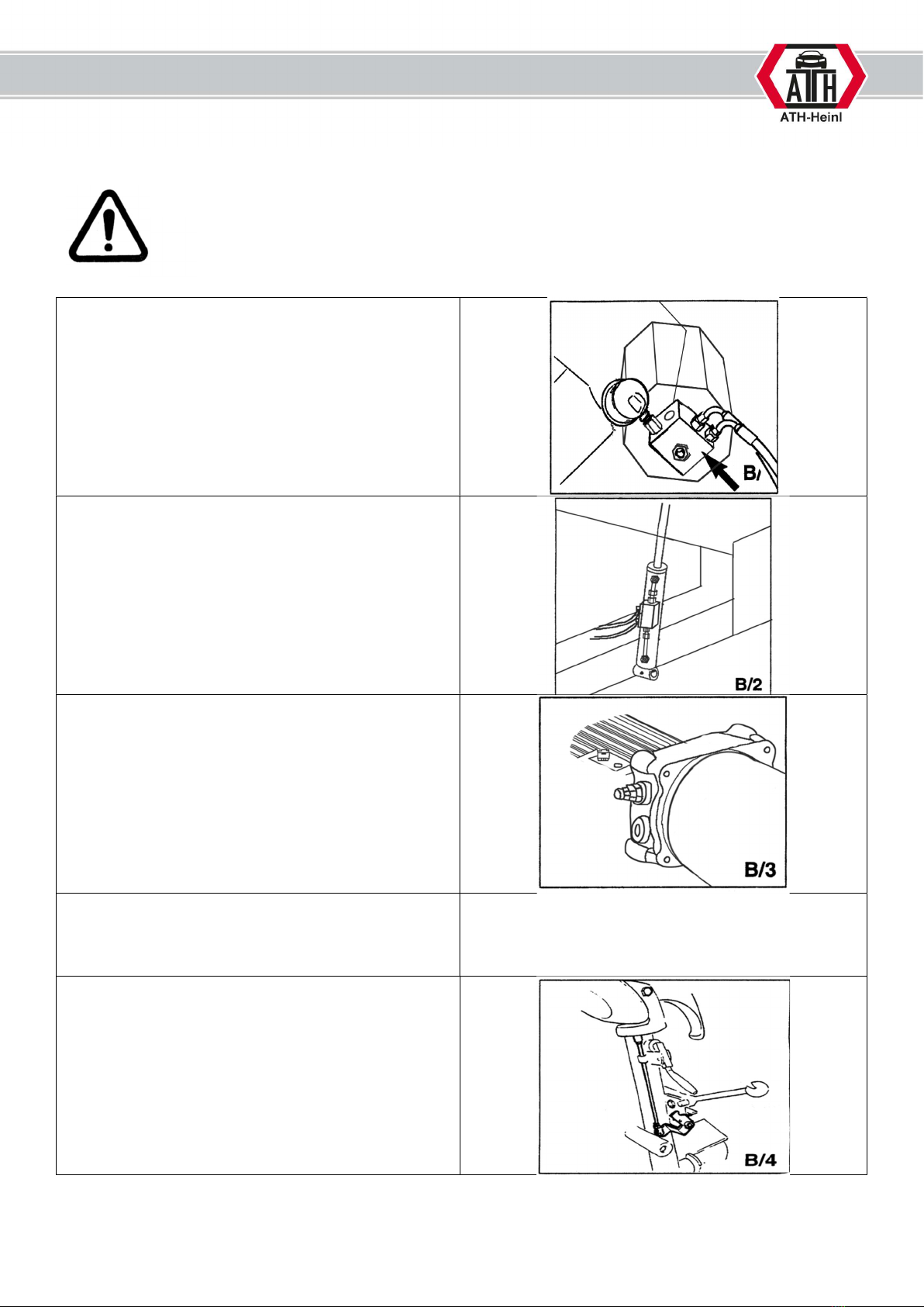
Check valve for the clamping cylinder of the 4-jaw
clamping unit (swivel connection)
Double seal check valve on the lift cylinder of the
boom.
Pressure relief valve with factory setting of 160 bar
± 5%
This limits the hydraulic pressure and is adjustable.
Overload protection for hydraulic motor (in the
electrical control box).
This cuts off the power supply when the engine
overheats
Mechanical locking of the tool arm

® Copyright ATH-Heinl GmbH & Co. KG, 2019, All rights reserved / Misprints and technical changes reserved / As of: 2019-01
Manufacturer ATH-Heinl GmbH & CO.KG
- 6 -
1.3 Operation
1.3.1 Review of the different functions
Before using the tyre changer, check all functions with the operating part to ensure the machine is working
properly. This should be done before mounting.
WARNING!!
When operating the mounting machine, pay attention to all moving parts.
Make sure there is enough safety clearance. Make sure there are no other
people in the work area.
WARNING!!
Always keep enough safety clearance when loosening the mounting arm so
that it does not tilt outwards under tension.
WARNING!!
Ensure that there are no persons or objects in the working area of the
machine.
WARNING!!
When closing the jaw chuck, the process must be stopped immediately when
the minimum position is reached.
When tightening the rim, stop immediately when the maximum pressure is
reached. For aluminium rims, check the clamping pressure and set it lower if
required.
Failure to comply with this instruction may result in serious damage to the
mounting machine.
1.3.2 Precautions during tyre assembly
Before mounting the tyre, the following precautions must be observed:
Only mount undamaged, clean, dry rims and tyres that are in good condition.
Remove old balance weights.
Check rim and tyre for damage, especially aluminium rims. Do not mount if damaged.
Check that the rim and tyre size match.
Before dismantling, let all air out of the tyre.
Before mounting, coat the rim and tyre well with tyre lubricant to avoid damage.
Always use a new valve.
The tyre changer is not splash-proof, so do not clean wheels on the machine with water jets.
® Copyright ATH-Heinl GmbH & Co. KG, 2019, All rights reserved / Misprints and technical changes reserved / As of: 2019-01
Manufacturer ATH-Heinl GmbH & CO.KG
- 7 -
1.3.3. Operating the tyre mounting machine
This instruction manual only details the function of the machine, it does not replace professional training
and qualification of operating personnel.
WARNING!!
All tyre changers have movable or adjustable controls. It is essential to ensure
that the operator finds a working position where he can safely track and view
all work steps.
We have provided videos online that offer assistance in using the machine:
Link: https://www.youtube.com/watch?v=DwEDbsz6PAA
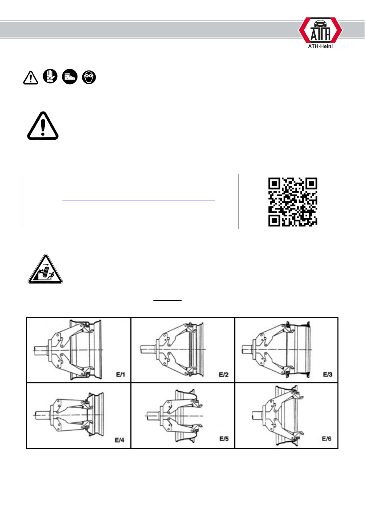
1.3.4. Clamping the wheel
WARNING!!
When tightening the rim, make sure that the clamping jaws are correctly
positioned on the rim to prevent the wheel from falling down.
There are different types of truck rims (Fig. 8 E/1-E6).
Use the four clamping jaws to select the appropriate clamp for the rim.

® Copyright ATH-Heinl GmbH & Co. KG, 2019, All rights reserved / Misprints and technical changes reserved / As of: 2019-01
Manufacturer ATH-Heinl GmbH & CO.KG
- 8 -
Place the tyre on the inside of the table for the mounting arm.
Continue moving the table until just before the clamping jaws.
Lower the clamping head to the centre of the rim.
Open the clamping jaws until they are smaller than the diameter of the mounting hole.
Slide the tyre over the clamping jaws and open until the tyre is tight.
Check that the rims sit correctly in all four jaws and that the tyre turns smoothly, otherwise it is not
possible to assemble.
WARNING!!
Note that the most secure tension is always at the inner hole.
WARNING!!
Never leave the work area while the wheel is still raised or tensioned.
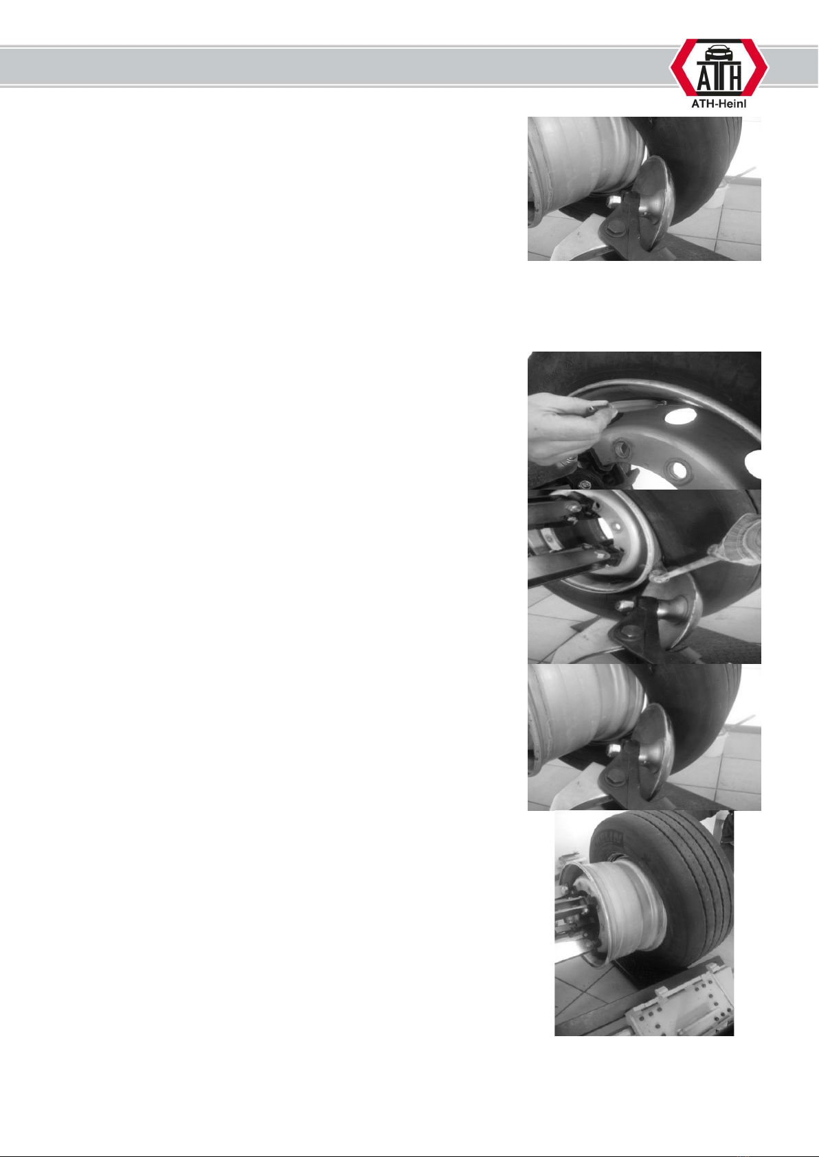
1.3.5. Removing a tyre
Use the valve driver to let the air out of the tyre.
The tyre bead must first be completely pressed off from both sides
of the rim with the mounting plate. During this process, the
mounting paste is applied to the rim and the tyre bead.
The first bead with rim mounting hook is now mounted.
Feed the mounting hook between the bead and the rim.
The tyre is then levered over the rim by lowering the rim and
pulling the mounting hooks.
Turn counterclockwise to remove the bead.
® Copyright ATH-Heinl GmbH & Co. KG, 2019, All rights reserved / Misprints and technical changes reserved / As of: 2019-01
Manufacturer ATH-Heinl GmbH & CO.KG
- 9 -
Now remove the second bead with the bead breaker.
1.3.6. Removing a tyre with just a bead breaker
The tyre bead can be dismantled by pulling on most wheels.
Use the valve driver to let the air out of the tyre.
Pull apart both beads and apply plenty of tyre bead lubricant.
The tyre can then be jacked apart from the inside out with the
mounting plate.
Before the tyre is completely removed, remove the mounting plate
and move the rim down so that the tyre is pushed over the rim.

® Copyright ATH-Heinl GmbH & Co. KG, 2019, All rights reserved / Misprints and technical changes reserved / As of: 2019-01
Manufacturer ATH-Heinl GmbH & CO.KG
- 10 -
WARNING!!
If the tyre is pushed over the second shoulder, it may fall off. Take
appropriate precautions.
1.3.7. Mounting a tyre
Generously apply tyre bead lubricant to the rim and tyre.
The first bead is mounted by pushing in and turning the rim.
The second bead is mounted with the bead retaining clip. A
mounting plate can be used on several tyres.
Install the tyre clamp at the 6 o'clock position and mount it with the
mounting disc. This is a simple and straightforward mounting.
Table of contents
Other ATH Tyre Changer manuals

Popular Tyre Changer manuals by other brands


Coats
Coats 80C operating instructions

HENNESSY INDUSTRIES
HENNESSY INDUSTRIES Coats Rim Clamp X-Model Series instructions

Draper
Draper 78612 user manual

Aston Global
Aston Global ATC-5800 Installation, Operation and Maintenance User’s Manual

HENNESSY INDUSTRIES
HENNESSY INDUSTRIES Coats CHD-4730-4730W Operating and maintenance instructions

Butler
Butler NAV11N instruction manual