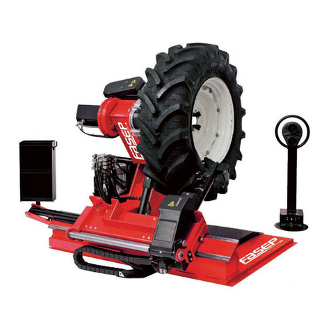
Fasep RGU588E Installation and operating instructions

UNIVERSAL TYRE-
CHANGER
INSTALLATION, USE AND
MAINTENANCE GUIDE
RGU588E
ed.09/15
Cod. 3014834 V
Original instructions

1. GENERAL INFORMATION page 6
2. TECHNICAL DATA page 6
3. GENERAL SAFETY REGULATIONS page 6
4. SAFETY DEVICES page 7
5. TRANSPORT page 7
6. UNPACKING page 8
7. INSTALLATION page 8
7.1 Installation site page 8
7.2 Workplace requirements page 8
7.3 Electric hook up page 9
Check of motor rotation page 9
8. CONTROLS DESCRIPTION page 10
9. DESCRIPTION OF THE MAIN COMPONENTS page 11
10. WARNING STICKERS page 12
10.1 Key to the warnings page 14
11. WORKING POSITION page 15
12. CHECK OF CORRECT OPERATION page 15
13. USE page 17
13.1 Wheel clamping page 17
Clamping of alloy rims page 18
Clamping extensions page 19
13.2 Tubeless and supersingle wheels page 19
Bead breaking page 19
Removing page 21
Mounting page 22
13.3 Tube tyres page 25
Bead breaking page 25
Removing page 26
Mounting page 26
13.4 Wheels with split ring page 29
Bead breaking and removing page 29
Mounting page 31
14. ORDINARY SERVICE page 34
15. TROUBLE SHOOTING page 36
16. HANDLING page 37
17. STORAGE page 37
18. SCRAPPING page 38
19. SERIAL PLATE DATA page 38
20. ACCESSORIES page 39
ELECTRIC AND HYDRAULIC DIAGRAMS page 41
CONTENTS

6
GENERAL INFORMATION
1
This tyre-changer has been specically designed to demount and mount truck, bus, tractors and earth moving
vehicles tyres, with rims from 14" to 56" and 2500 mm. max. diameter.
Any other use is improper and therefore not authorized.
Before starting any kind of work on this machine, carefully read and understand the contents of these
operating instructions.
It is forbidden to use the machine for straightening rims, breaking beads of still inated or dirty tyres, turning,
rasping, cutting tyres.
The Manufacturer is not liable for any injury to persons or damage to things caused by a misuse of this
machine.
KEEP THIS MANUAL IN A SAFE PLACE AND CONSULT IT WHENEVER IN NEED.
GENERAL SAFETY REGULATIONS
3
The use of this machine is strictly reserved to trained and authorized staff.
Any tampering or modication, if not previously authorized by manufacturer, relieves this one of all possible
damages referred to the mentioned actions.
Any removal or tamper with the safety devices installed in this machine will represent a violation of the
European regulations.
Any work on the electrics, however
minor, mustbedone exclusively be
professional staff.
2TECHNICAL DATA
3 kw
1,85 - 2,5 kw
14" - 56"
2000 kg
2.500 mm
1.500 mm
1.300 Kg
LpA <70 dB (A)
NOTE: Part of the illustrations contained in
this book has been taken on prototypes.
Some current components might therefore
differ from what shown herein.
Pump motor
Gear box motor (2 speed)
Clamping range
Max. wheel weight
Max. wheel diameter
Max. wheel width
Weight (standard outt included)
Acoustic pressure level (at work)

7
SAFETY DEVICE
4
The tyre-changer is equipped with several safety devices to grant the utmost safety at work:
1) Check valve on the chuck opening hydraulic line (inside the rotating union, see Fig. B/1). This prevents the wheel from
falling from chuck down to oor if the hydraulic circuit accidentally breaks.
2) Pilot operated seal check valve (see Fig. B/2)
It prevents the chuck holder from falling down if the hydraulic circuit accidentally breaks.
3) Pressure relief valve. Two available, one preset at 130 bar ±10% for the self-centering chuck (ref. 1 – B/3) and one
preset at 170 bar ±10% for using the machine functions (ref. 2 – B/3).
It limits the pressure in the hydraulic circuit and ensures correct operation of the plant.
4) motors overload cut-outs (inside the electric unit). They get engaged in case the motor overheats, so preventing it from
burning out.
If the tyre-changer is equipped with the RC Radio Control, the mobile control stand is connected with the machine frame through
a steel wire that prevents the operator from going too far so working without seeing the machine.
CAUTION! Removing or tampering with safety devices represents a violation of the European Safety Regulations and relieves
the manufacturer of any and all liability for injury to persons or damage to things caused or referable to such acts.
TRANSPORT
5
Depending on customer request, the machine can be delivered in 3 different packing versions:
1- in a wooden crate on pallet
2- xed onto a pallet
3- with no packing at all
In all cases the machine will be protected by a plastic covering.
In the rst and second case, the machine must be handled with a fork lift truck with the forks positioned as shown
in Fig. A/2
For the third case, follow the instructions given on page 35 of this manual, chap. 16 – Handling.
Shipping weight of the machine is 1.550 kg.
KG. 1.550
B/3
B/2
B/1
A/2
2
1

8
UNPACKING
6
Once the packing material has been removed, check the machine visually for integrity and make sure there are no
damaged parts.
Keep the packing materials out of the reach of children as they can be a source of danger.
N.B. Keep the packing for possible future transport.
INSTALLATION
7
Chose the installation site according to the current rules on Safety at Work.
The oor shall not be uneven as to grant stability to the machine.
Outdoor installation requires a weatherproof roof.
The working area must be in accordance to the following requirements:
- relative humidity from 30% to 95% without condensate;
- temperature between 0° and 55°C.
IT IS FORBIDDEN to use the machine in explosive atmosphere.
Overall dimensions of this machine are 2600x3150mm. considering a min. distance from walls as shown in Fig. B/4.
Make sure the ceiling is at least 3m. high.
ATTENTION! The dimensions above also refer to the working area. Bystanders and persons other than
trained and authorized staff are strictly forbidden to enter this area.
Set the forks of the lift truck into the slots 1 and 2 made in the machine baseframe expressly to move it and set it
in position.
It is, furthermore, possible to use the hooks placed at the machine corners and those on the chuck carriage (g. A,
ref. 3,4,5,6), by means of lifting bands having adequate capacity (see technical data, page 4). Keep the hooks for
any further need of moving the machine to a new installation site.
Recommended fork lift truck requirements: 2000 kg. min. lifting capacity; 1300 mm. fork length.
It is not essential to anchor the machine to oor. Just make sure it is well stable and set shims wherever levelling is
necessary. This will grant good operating process after setting the machine at work. Set shims wherever necessary
and use the proper fastening holes.
2500 mm
2500 mm
600 mm
7.1
INSTALLATION SITE
7.2
WORKPLACE REQUIREMENTS
1500 mm
B/4
A
1
2
3
4
5
6

9
7.3
ELECTRIC HOOK UP
Before making any electric hook up, carefully check that the mains voltage corresponds to the data given
on the voltage tag (positioned near the tyre-changer plug).
Following requirements are essential:
- the system must be equipped with a good earthing circuit
- the machine must be connected to a power supply line circuit breaker set at 30 mA
- the plug must be properly protected against overcurrent by means of either fuses or an automatic
magneto-thermal switch with rated values as shown in the chart.
Read the required power draw as highlighted in the data plate xed to the tyre-changer and make sure that the
electric network is properly dimensioned to it.
WARNING! Make sure that the feeding cable, once connected to the electric network, can freely move and
follow the stroke the chuck holder without risk of damage.
Failure to comply with above mentioned requirements will relief the manufacturer from any and all liability
for any injury to persons or damage to things referred to these acts and it will involve the immediate expiry
of warranty.
Check the tyre-changer to the network, turn on the main switch (5, g. A) and check the rotation direction of the
motor. It must correspond to the direction shown by the arrow (6, g. A). If not, have two wires in the plug (3ph)
reversed by professional staff.
CHECK OF MOTOR ROTATION
10 A
10 A
8 A
8 A
13,5 A
13,5 A
6,3 A
6,3 A
Interruttore Interruttore
Switch Switch
Interrupt. Interrupt.
Schalter Schalter
Interruptor Interruptor
220 V. - 3 Ph. - 50/60 Hz.
240 V. - 3 Ph. - 50/60 Hz.
380 V. - 3 Ph. - 50/60 Hz.
415 V. - 3 Ph. - 50/60 Hz.
Alimentazione
Power supply
Alimentation
Stromversorgung
Alimentación
A
5
6
Any work on the electrics, however
minor, must be done exclusively be
professional staff.

10
8
CONTROLS DESCRIPTION
The mobile control stand (g. C) enables the operator to work at any position around the machine. On this mobile
stand the following controls are located:
- the joystick 1(1, g. C) in position A let the chuck holder move away from the tool holder; in position Bit moves
it in opposite direction; in position Dit moves the chuck arm holder rightwards and the tool holder leftwards
simultaneously (so they get close to each other); in position E it moves the chuck arm holder leftwards and the
tool holder rightwards simultaneously (so they get far from each other).
- The joystick 2 (2, g. C) controls all the tool’s movements; in position F (up) it brings the tool arm to “rest
position”; in position G (down) it brings the arm in “work position”; in position H(left) it controls 180° anti-clockwise
rotation of the tools; in position I(right) it controls opposite rotation so bringing the tools in the initial condition.
- Switch 3 (3, g. C) if pushed up to position L it makes the chuck rotate at the double of the speed set when
selecting position M(up).
- Switch 4 (4, g. C) let the chuck holder arm and the tool holder arm move at the same time either at high speed
(pos. N) or at reduced speed (pos. O)
- Switch 5 (5, g. C), if pushed up to pos. P, it let the chuck jaws open (LOCK), if pushed down to pos. Qit let
the chuck jaws close (UNLOCK)
- Switch 6 (6, g. C) let the chuck move up (pos. R) and down (pos. S)
- The balance pedal (7, g. C) let the chuck rotate in the direction shown by the arrow stuck on both pedal sides
(Tand U).
REMARKS: all the controls available in the mobile column are very sensitive, so granting the smallest movement
with the highest precision.
On the tyre-changer, knob (19, g. D) is also available for replacing the mounting tool whenever necessary (f.i. to
install the RT tubeless roller tool)
D
18
19
17
C
P
R
S
6A
B
D1E
L
M
3F
5
Q
N
O
4
H
G
I
2
U
T
7

11
DESCRIPTION OF
THE MAIN COMPO-
NENTS
9
1) Joysticktocarriagesmovement
2) Joystick to tool
3) Chuck speed rotation switch
lever
4) Hydraulic speed switch lever
5) Chuck opening/closing switch
lever
6) Chuck arm up/down switch
lever
7) Chuck rotation control pedal
8) Chuck arm
9) Chuck
10)Jaws
11) Main switch
12)Base platform
13)Tool holder carriage
14)Tool holder
15)Chuck carriage
16)Chuck holder carriage
17)Bead breaking disk
18)Finger tool
19)Tool fastening knob
ATTENTION!
Keep as far as possible from moving
parts. Necklaces, bracelets and too
large clothes can be a source of
danger for the operator.
For the same reason, long
hair must be tied up.
D
A
12
11
18
19
17
14
13
C
15
8
9
10
16
P
R
S
6A
B
D1E
L
M
3F
5
Q
N
O
4
H
G
2
T

12
3008615
3006037
3014771
3014772
3005417
3014774
3014775
3000961
3008614
3008616
3014337
3005087
3005410
3005423 3005419
3014767
3006037 3006038
3005421

13
WARNING STICKERS
10
ATTENTION:
Unreadable or missing stickers must be immediately replaced.
Do not use the tyre-changer if one or more stickers are missing.
Do not add any object that could prevent the operator from seeing
them.
3014776
3000964
3014770 3000965
3014773
3000961
3014768
3014769

14
Danger of crushing hands in the chuck jaws.
10.1
KEY TO THE WARNINGS
Pay the utmost attention during tool holder tilting
operation.
Danger of crushing feet during chuck rotation or opening
operation
Danger of crushing between chuck holder and tyre-
changer platform.
Danger of crushing between chuck and tool.
Danger of wheel falling down.
Live electric voltage

15
CD
Diagram B/8 shows the several working positions (A, B, C, D) that will be described in the following pages. Working
from these positions ensures greater precision, higher speed and safety level to the operator
WORKING POSITION
11
Before using the tyre-changer, some checks shall be made to grant correct operation.
ATTENTION: perform the following checks keeping the tool hold-arm (14) in “rest position”.
1) Move the joystick (2, Fig. C page 9) UP (pos. F): the tool holder (14, Fig. D) must tilt to “rest position”.
CHECK OF CORRECT OPERATION
12
Move the joystick (2, Fig. C page 9) DOWN (pos. G): the tool holder (14, Fig. D) must tilt and hook into “work
position”.
Move the joystick leftwards (pos. H): tools must rotate by 180° on their axle counterclockwise; move the joystick
rightwards (pos. I): tools must reverse rotation and go back to initial position.
2) With tool holder in “rest position”, move the switch lever (6, Fig. C page 9) UP (pos. R): the chuck holder (8, Fig.
A) must move upwards; move the switch lever DOWN (pos. S): the chuck holder must move downwards;
ATTENTION!!
Don’t keep your face close to the tool holder during tilting operation.
B
A
B/8
D
18
17
14
A
8

16
move the joystick (ref.1 g. C page 9) leftwards (D): the chuck holder (8, Fig. A) must also move leftwards and, at
the same time, the tool holder (14, Fig. D) must move rightwards (getting far from each other);
repeat the operations (D) and (E) moving the switch lever (ref. 4, g. C, page 9) to the other possible position:
movements must take place at a different speed (lower or higher according to the selected position, N or O).
3) move the joystick (5, g. C, page 9) UP: the chuck jaws (9, g. A) must open; move the joystick DOWN: the jaws
must close.
Move the joystick (ref.1 g. C page 9) rightwards (D): the chuck holder (8, Fig. A) must also move rightwards and, at
the same time, the tool holder (14, Fig. D) must move leftwards (getting close to each other).
Repeat the operations above moving the switch lever (ref. 3, g. C, page 9): movements must take place at different
speed.
ATTENTION!
When the chuck holder moves down, it creates potential crushing points. Always work in the positions
given by this guide, keeping outside the action range of moving arms.
ATTENTION!
During the chuck jaws opening/closing movement there’s the risk of potential crushing points. Always
work in the positions given by this guide, keeping outside the chuck action range.
4) Press the pedal (ref.7, g. C, page 9) in its right side: the chuck (9, g. A) must rotate clockwise; press it in its left
side: the chuck must rotate counterclockwise.
Move the switch lever (3, Fig. C, page 9) DOWN and repeat the operations above: movements must take place at
a doubled speed.
5) Check the good functioning of hydraulic circuit:
- turn the switch (5, g. C, page 9) UP and keep it that position until the chuck jaws have fully opened.
A
9
10
8
D
18
19
17
14
13

17
13.1
1) Set the mobile control unit in position B (Fig. B/8, page 13)
2) Tilt the tool holder to rest position (14, g. D)
3) Use the joystick to move the chuck leftwards until there’s place enough to let the wheel be set on the
platform. Keep the wheel in vertical position.
WHEEL CLAMPING
USE
13
WARNING!
In clamping phase, make sure the clamps have been correctly positioned on the rim, so
preventing the wheel from falling off.
WARNING!
This operation can be extremely dangerous. Do it manually only if you are certain you can keep the
wheel balanced. Heavy tyres (over 110kg) and/or oversize tyres (with diameter over 130cm) shall
never be lifted by hand. Let them roll on oor and lift them by means of an adequate mechanical
lifting device.
A
D
18
19
17
14
13
9
10
8

18
A kit of jaws item 137/90, available on demand, is expressly designed for operating on alloy rims without
damaging them.
The jaws are to be inserted (bayonet-like mounting) into the jaw support of the self-centering chuck (see g.
E7, page 17)
Thanks to a wingscrew they can be easily locked on the support
Lock the rim as shown by g. E
To operate on such wheels, it is also available item 138/90, alloy-rim gripper.
CLAMPINGOF ALLOY RIMS
4) Use the joystick to keep on moving the chuck arm up and down to centre the chuck (9, g. A) to the rim
5) With the jaws (10, g. A) closed, move the chuck against the wheel, then use the switch (5, g. C, page
9) to open the jaws so clamping the rim from inside, in the most suitable position according to the kind of rim
(to be chosen among those shown in Fig. E1/E2/E3/E4/E5/E6
Always remember that the safest locking is on the central ange.
NOTE: for rims with reversed groove, lock the wheel as to let the groove outside (see g. E1
E
E/1 E/2
E/3 E/4
A
9
10
8

19
13.2
TUBELESS AND SUPERSINGLE WHEELS
BEAD BREAKING
1) Lock the wheel on the chuck, as previously described, and make sure it is deated.
2) Set the mobile control unit in working position C (g. B/8, page 13)
3) Lower the tool arm (14, g. F) to working position, until it gets locked by the ratchet.
ATTENTION!
Always make sure that the arm is correctly hooked to the carriage.
ATTENTION!
The bead breaking disk must not be pressed against the rim but against the tyre
bead.
4) Use the joystick to position the wheel in a way to let the rim outer prole graze the bead breaking disk (g.
F)
Rims having diameter over 46" without central hole ange can be clamped with the kit of 4 extensions, item
140/90 (available on demand)
Insert the extension on the support (bayonet-like mounting) and lock it by the wing nut (see g. E8).
ATTENTION!
Do not leave working area with a wheel clamped on the tyre-changer and lifted up from oor.
CLAMPING EXTENSIONS
E/5 E/6
E/8
F
14

20
Always remember that the stronger is the tyre’s adherence to rim, the slower must be the disk’s
penetration.
7) Use the joystick (2, g. C, page 9) to move the tool arm to rest position, move it up and turn the tool by
means of the proper knob. Move the tool arm to the left of the wheel to be demounted, lower it and move it
to work position (g. G)
ATTENTION!
Do not keep your hands on the tool when moving it to work position, because they could
get trapped between tool and wheel.
5) Let the wheel rotate and, at the same time, let the bead breaking disk move forward, with a stick-slip
motion, following the rim prole as well as possible.
6) Go on until the rst bead is fully detached.
To facilitate this operation, grease tyre bead and rim edge while the wheel is rotating.
ATTENTION!
To avoid any risk when greasing the beads, make the wheel rotate CLOCKWISE if you are
greasing the outer bead, COUNTERCLOCKWISE if you are greasing the inner bead.
8) Use the joystick (1, g. C, page 9) to move chuck and tool arm until this one is in the inner side of the
wheel.
9) Use the joystick (2, g. C, page 9) to move the arm back to work position and turn the tools by 180°
Set the mobile control unit in work position
Repeat the operations described by point 5) and 6) until the second bead is fully detached.
NOTE: during bead breaking operation, the nger tool (18, g. G) can be lowered so that it won’t be an
obstacle.
C
1
2
F
14
G
19
18

21
SMONTAGGIO
- Insert the lever (17, g. I) between rim and bead, at the right of the tool.
- Keeping the lever pressed, move the wheel down until the rim edge is at about 5mm. distance from the
nger tool
- Let the wheel rotate counterclockwise, keeping the lever pressed, until the bead is fully detached.
- Move the tool arm to rest position, then bring it to the inner side of the wheel.
- turn the nger tool by 180°, insert it between rim and bead (see g. L) and move it until the bead gets
close to the rim front edge (it is recommended to perform this operation while rotating the wheel)
move the rim from tool of about 4-5 cm. as to prevent the tool from releasing the bead.
Tubeless tyres can be removed in two different ways:
1) If the wheel doesn’t present any particular difculty, after bead breaking proceed pushing the bead breaking
disk against the tyre inner side until the two beads get out of the rim (see g. H).
2) if the wheel is a SUPERSINGLE type, or particularly hard anyway, it is not possible to proceed as described
above. In this case it is necessary to use the nger tool and proceed as described below:
- move the tool arm to the outside plane of the tyre
- let the wheel rotate and, at the same time, move the nger tool forward until it is introduced between
rim and bead, well anchored to the bead (see g. I)
- move the rim from tool of about 4-5 cm. as to prevent the tool from releasing the bead.
- Move the nger tool outward until the red spot in it gets close to rim outer edge.
Set the mobile control unit in work position C (g. B/8, page 13)
Set the mobile control unit in work position B (g. B/8, page 13)
Set the mobile control unit in work position D (g. B/8, page
13)
L
H
I
17

22
- Move the nger tool until the red spot in it is about 3 cm. inside the rim.
- Insert the lever (17, g. I) between rim and bead, at the right of the tool.
- Keeping the lever pressed, move the wheel down until the rim edge is at about 5mm. distance from the
nger tool, then let the wheel turn counterclockwise until the tyre is full detached.
Set the mobile control unit in work position B (g. B/8, page 13)
ATTENTION!
The detachment of the beads might cause the tyre to fall down. Always make sure there
are no by-standers inside the working area.
MOUNTING OPERATION
Tubeless tyres can be mounted using either the disk or the nger tool
If the wheel doesn’t present any particular difculty, it is suggested to use the disk; otherwise the nger tool
will be required.
MOUNTING OPERATION WITH DISK
Proceed as follows:
1) if the rim is released by the self-centering chuck, clamp it again as described in par. “WHEEL
CLAMPING”
2) grease beads and rim
3) set the in the highest position of rim outer edge (see g. M)
4) Set the tyre on the machine baseframe and lower the chuck (taking care to keep the gripper in highest
position) to hook the rst bead to the gripper.
5) Lift the rim with hooked tyre and let it rotate counterclockwise of about 15-20 cm. The tyre will set itself
slantways.
ATTENTION!
Make sure that the gripper is well secured to the
rim.
Set the mobile control unit in work position B (g. B/8, page 13)
M
L
I
17

23
Set the mobile control unit in work position C (g. B/8)
6) Set the disk against the second bead and turn the chuck until the gripper is in the lowest position (at 6
o’clock)
7) move the disk away from the wheel
8) remove the gripper and reinstall it again in the lowest position (at 6 o’clock) but out of the second bead
(see. Fig. N)
9) turn the chuck clockwise by 90° to bring the gripper to 9 o’clock.
10) Move the disk inwards of about 1-2cm. from the rim edge, taking care to let it at about 5mm. from the
prole. Start clockwise rotation checking the second bead that, after 90° rotation, shall start slipping into the
rim groove.
11) at the end of mounting phase, move the tool away from the wheel, tilt it to rest position and remove the
gripper
12) lower the chuck until the wheel rests on the machine baseframe.
Set the mobile control unit in work position C (g. B/8)
13) close the chuck jaws completely, taking care to hold the wheel to prevent it from falling off.
ATTENTION!!
This operation can be extremely dangerous. Do it manually only if you are certain you can
keep the wheel balanced. Heavy tyres (over 110kg) and/or oversize tyres (with diameter over
130cm) shall never be lifted by hand. Let them roll on oor and lift them by means of an
adequate mechanical lifting device.
14) Move the chuck as to release the wheel
15) Move the wheel away.
NOTE: according to the tyre you are operating on, you can decide to speed up the a.m. operation,
mounting both beads at the same time:
- proceed as described in point 1,2,3,4 above, but instead of xing the gripper to only one bead (see point
4), x it to both.
- Lift the rim with the hooked tyre on it and turn it counterclockwise of about 15-20 cm. (gripper at 10
o’clock)
- Proceed as described from point 10 to 15 above.
CD
B
A
B/8
N
Table of contents
Other Fasep Tyre Changer manuals

Fasep
Fasep RASE.TOP.2248 User manual

Fasep
Fasep BALATRON B433.G3 User manual

Fasep
Fasep V548.G4.U User manual

Fasep
Fasep RASE.2234 User manual

Fasep
Fasep RGU2671.G User manual

Fasep
Fasep V585.2.U User manual

Fasep
Fasep RASE.2131.T User manual

Fasep
Fasep RGU300.ECO User manual

Fasep
Fasep RGU600E User manual

Fasep
Fasep TOP AUTOMATIC 4.0 Operating instructions
Popular Tyre Changer manuals by other brands

Hofmann Megaplan
Hofmann Megaplan Megamount 503e Installation, operation and maintenance guide - Original instructions

HPA-Faip
HPA-Faip M 322 Operator's manual

ATH
ATH M126 operating instructions

Hunter
Hunter TCX3000 instruction manual

Mondolfo Ferro
Mondolfo Ferro STAHLGRUBER TCN 8200 Operator's manual

Butler
Butler KENDO.30LIGHT instruction manual