Nietz NZ2000 Series User manual
IW
IETZ
NII:TZ
ELECTRICCO.,LTD


•
Thank
you
very
much
for
your
buying
NZ2000
series
High-
performance Vector Control Inverter.
• Before use, please read this manual thoroughly to ensure proper
usage. Keep this manual at an easily accessible place so that can
refer anytime as necessary.
Safely
Precautions
Please read this operation manual carefully before installation,
operation, maintenance
or
inspection In this manual, the
safety
precautions were sorted
to
'WARNING" or "CAUTION".
A
wARNING
,A
cAUTION
Indicates a potentially dangerous situation which,
if
can
not
avoid will result in death
or
serious
injury.
Indicates a potentially dangerous
si'b..Jation
which,
if
can
not
avoid will
cause
minor
or
moderate
injury and damage the device.
This
Symbol is
also used forwarning any un-safaty operation.
In
some cases, even the contents
of
NCAUTION"
still can cause serious accident. Please
follow
these important precautions in any situation.
In some cases, even the contents
of
"CAUTION" still can cause
serious
accident
Please follow these important precautions
in
any
situation.
In some cases, even the contents
of
"CAUTION" still can cause
serious accident. Please follow these important precautions
in
any
situation.
*NOTE indicate the necessary operation
to
ensure the device run
properly.
Warning Marks are placed on the front cover
of
the inverter.
Please follow these indications when using the inverter.
WARNING
• May cause injury
or
electric shock.
• Please follow the instructions in the manual before installation
or
operation.
• Disconnect all power line before opening front cover
of
unit. Wait
at
least 10 minutes until DC Buscapacitors discharge.
• Use proper grounding techniques.
• NeveroonnectAC power
to
output UVWterminals.
Instruction
of
NZ2000 Series Inverter
Contents
Chapter1 Introduction..........•................•......................•...............1
1.1
Technology Features ...........................................................1
1.2
Description
of
Name
Plate..................................................3
1.3 Selection Guide....................................................................4
Chapter2 lnalallation and wiring.................................................5
2.1
Environment
and
Installation requirements ..........................5
2.2 The opening size ofthe keyboard ........................................8
2.3 The InverterWiring ...............................................................8
2.3.1
The inverterwiring
of
the main part...........................8
2.3.2 the descriptions
of
peripheral devices..... ......9
2.3.3 Precautions
main
circuit wiring ..................................9
2.3.4 Device recommended specifications....... .
...
10
2.3.5
Main
circuit terminals
and
description......................
11
2.4 Control Terminals................................................................13
2.4.1
Control
Terminal
Descriptlon....................................13
Chapter3 Operation..............•................•......................•.............15
3.1
Digiml
Operator Doscliption .............................................15
3.1.1 the picture
of
the
panel
............................................15
3.1.2 the descriptions a!
the
key's function.......................15
3.1.3 Indicator light descliptlons.......................................16
Contents 1
Contents
3.2
Operational process .........................................................16
3.2.1
Parameter Settings..................................................16
3.2.2 Fault reset................................................................17
3.2.3 Motor parameter self leaming..................................17
3.3
Running
slate .....................................................................18
3.3.1
Power-on initialization ............................................18
3.3.2 Standby status ........................................................18
3.3.3 Motor paramelers sell-learning ..............................19
3.3.4 Running ...................................................................19
3.3.5 Failure....................................................................19
3.4 Quick commissioning .........................................................19
Chapter4 Detailed Function Description....................•.............
21
Chapter5 Faullchocking and ruled out......................•...........116
5.1
Fault alarm
and
oounterrneasures....................................
116
5.2
Common
Faults
and
Solutions ....
,,
........
,,
.......
,,
.......
,,
121
Chapter6 lllalntonanco.........•................•......................•...........123
6.1
Inspection.........................................................................123
6.2
Periodic Maintenance.......................................................123
6.3 Replacement ofwearing par!s..........................................
124
6.4 Inverter
Wanrsnty
..............................................................
124
Chapter7 Peripheral Devices Selection..................................125
7.1
Peripheral Devices Description .....................................
,,
125
7.2
Applied Braking resistor Specification ..............................125
Contents
2

Instruction
of
NZ2000
Series
Inverter
AppendixA
list
of
Function Parametsrs................................127
Appendix B Communication Protocol..•......................•...........166
Contents
3
Chapter 1 Introduction
Chapter 1 Introduction
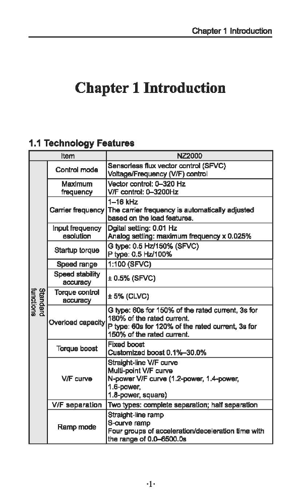
1.1 Technology Features
Item NZ2000
Control mode Sensorless
nux
vectorcontrol (SFVC}
Voltage/Frequency (V/F) control
Maximum Vectorcontrol: 0--320
Hz
frequency V/F control:
0-3200Hz
1-16kHz
Carrierfrequency
The
carrier frequency is aulomaticallyadjusted
based
on
the load features.
Inputfrequency Dgital setting: 0.01
Hz
esolution Analog setting: maximum frequencyx 0.025%
Startup lorque G type: 0.5 Hz/150% (SFVC}
P type: 0.5
Hz/1
00%
Speed range 1
:1
00(SFVC)
Speed stability ± 0.5% (SFVC}
accuracy
~~
Torque control
±5%(CLVC)
!l.:>
accuracy
~-~
G type:
60s
for
150%
oftherated current, 3s
for
Overload capacity 1
BO%
of
the
rated current.
P type: 60s
for
120%
of
the rated current,
3s
for
150% of
the
rated current.
Torque boost Fixed
boost
Cuslomlzed
boost
0.1%-30.0%
straight-lineVJF curve
Multi-point
VJF
curve
VJF curve N-power
VJF
curve (1.2-power, 1.4-power,
1.6-power,
1.8-power, square}
V/F
separation
Twotypes: complete separation; halfseparation
Straight-line ramp
Ramp
mode S-o...rve ramp
Four groupsofacceleration/deceleration time with
the range
of
0.0-6500.08
·1·

Operation Instruction
of
NZ2000 Series Inverter
Item
NZ2000
DC
braking
frequency:
0.00
Hz
to
maximum
frequency
DC
braking Braking
Ume:
O.Q-100.0s
Braking action currentvalue: 0.0%-100.0%
JOG control
JOG
frequencyrange: 0.00-50.00 Hz
JOG
acceleration/deceleration time: 0.0-6500.0s
Onboard
multiple It implements
up
to
16
speedsviathe simple
PLC
preset
speeds
function orcombination
of
Xterminal states
Onboard
PID
Itrealizes process-controlled
closed
loop
control
system
easily.
Auto voltage It
can
keep
constant outputvoltage automatically
regulation
(AVR)
when
the
mains
voltage
changes.
Overvoltagal The current
and
voltage
ara
limited
automatically
Overcurrent stall during the running process so
as
to
avoid
fnsquent
control tripping
due
to
overvoltage/overcurrent.
Torque
limit
and
It
can
limit
the
torque
autDmatically
and
prevent
frequent
control
ovar
cull'llnt
tripping
during
the
running
procass.
;:-en
The
load
feedback energycompensates the voltage
~S'
Instantaneous
g&
stop
doesn't stop reduction
so
that
the
AC
drive
can continue to run
...
! fora shorttime.
Rapid
current Ithelps to avoid frequent overcurrent faults
af
the
limit
AC
drive.
Control
of
asynchronous motor is implemented
High
performance through the high-performance current vector
control
technology.
Timing
control
Time
range:
0.0-6500.0 minutes
Communication
RS485
methods
Running
Givan
by
the
panel,
control
terminals,
command
Serial communication port,can
be
switched by
many
channel ways
10 kinds
of
frequency source,given by
Frequencysource Digital analog voltage, analog current,Pulse,
ser1al
port.
can
be
switched
by
manyways
Auxiliary 10 kinds
of
Frequencysource,can easily realize
frequency source Micro adjustment,frequencySynthesizer
6 digitalinput terminals,
one
ofwhich supports
up
to
1
00
kHz high-speed
pulse
input.
S' Input terminals 2 analog input terminal,
one
af
which only supports
Js
Q-10
Vvoltage inputand the othersupports
Q-10
V
voltage input or
4-20
mA
current input
.,
Ill
1digital output terminal
_,
0.
Outputterminal 1relay output terminal
1analog output terminal :that supports
Q-20
mA
current output or
Q-10
vvoltage output
·2·

Chapter 1 Introduction
Item NZ2000
LED
display Itdisplaysthe parameters.
ii
Key locking and Itcan lock
the
keys partially
or
completely
end
define
the
function range
of
somekeys
so
as
to
iii iii
function selection prevent mis..function.
""8'
g:::J
Motor
short-circuit detection
at
power-on, output
~~
Protection
mode
phase loss protecUon. over-current protection,
over-voltage protection,
under
voltageprotection,
overheatprotection
and
overload protection.
Installation Indoor, avoid
direct
sunlight, dust, corrosive gas,
location combustible gas, oil smoke, vapour, drip
or
salt.
m Altitude
Lower
than 1000m (Lower the grades
when
using
~-
higher
then 1
OOOm)
a
Ambient
-1
o·c
-<IO"C
(lower
lhe
grades iflheambient
:I
temperature temperatura Is
~
40"C
and
&rC)
3
Cl>
Humidity
Less
than 95%RH, withoutcondensing
::1.
Vibration
Lass
than
5.9
mls
2 (0.6
g)
Storage
-20"c-60"C
temperature
1.2 Description
of
Name
Plate
MODEL:
NZ2400-3R7G/5RSP-o
INPUT:
3PH
380V
50Hz/60Hz
OUTPUT:
3PH
380V
9.0113.0
FREQ
RANGE:
0.1-320Hz
3.7/S.SkW
ri
ii
Ulmllill[IJ[)
]]
JI CE
(14011311111)
MODE:
NZ-
2 -
400
-3R7G/5R5P- o
~
T specific symbol
L____=
(Blank fur normal product)
3R7:
3.7KW
G: Constanttorque
P: Variable torque
'--------
200: 1PH
AC220V
400:
3PH
AC380V
600:
3PH
AC660V
L....--------
2:
NZ2000 series inverter
8:
NZBOOO
series inverter
.__
__________
NZ: Trade
Mark
·3·
Operation Instruction
of
NZ2000 Series Inverter
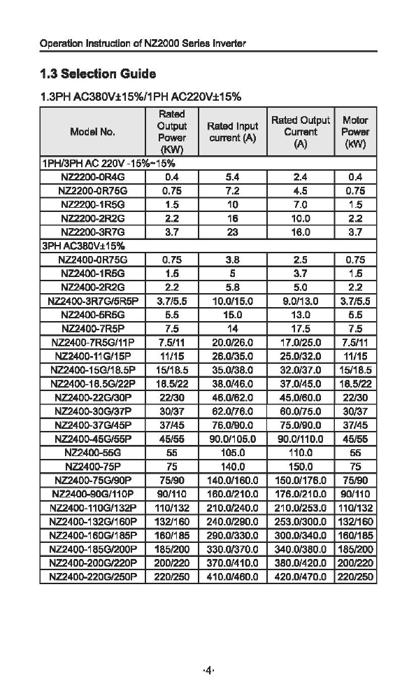
1.3 Selection Guide
1.3PHAC380V±15%/1PHAC220V±15%
Rated
Rated Output Motor
Model No. Output
Rated
Input
CuiTIIn
t
POWIIr
Power current
(A)
(A) (kW)
(KW)
1PH/3PH
AC
220V -15%-15%
NZ2200-0R4G
0.4
5.4
2.4
OA
NZ2200.()R75G 0.75
7.2
4.5 0.75
NZ2200-1R5G 1.5
10
7.0 1.5
NZ2200-2R2G 2.2
16
10.0
2.2
NZ2200-3R7G
3.7
23 16.0
3.7
3PH
AC380V±15%
NZ2400.()R75G 0.75 3.8 2.5 0.75
NZ2400-1R5G 1.5 5 3.7 1.5
NZ2400-2R2G 2.2 5.8 5.0
2.2
NZ2400-3R7G/5R5P 3.7/5.5 10.0/15.0 9.0/13.0 3.7/5.5
NZ2400-5R5G
5.5
15.0 13.0
5.5
NZ240Q-7R5P
7.5
14
17.5
7.5
NZ2400-7R5G/11
P
7.5111
20.0126.0
17.0125.0
7.5111
NZ2400-11G/15P
11/15
26.0135.0
25.0132.0
11/15
NZ2400-15G/18.5P
15118.5
35.0/38.0
32.0137.0
15118.5
NZ2400-18.5G/22P
18.5122
38.0/46.0 37.0/45.0
18.5122
NZ240Q-22GI30P
22130
46.0162.0
45.0/60.0
22130
NZ240Q-30G137P
30137
62.0/76.0 60.0/75.0
30137
NZ240Q-37G/45P
37/45
76.0190.0
75.0190.0
37/45
NZ240Q-45G/55P
45155
90.0/105.0 90.0/110.0
45155
NZ2400-55G 55 105.0
110.0
55
NZ240Q-75P
75
140.0
150.0
75
NZ240Q-75G/90P
75190
140.0/160.0 150.0/176.0
75190
NZ240Q-90GJ110P
901110
160.01210.0
176.0121
0.0 90/110
NZ2400-110GI132P
110/132
210.01240.0
21
0.01253.0
110/132
NZ240Q-132G/160P
132/160
240.01290.0
253.01300.0
132/160
NZ240Q-160G/185P
160/185 290.0/330.0
300.01340.0
160/185
NZ240Q-185G/200P
1851200
330.0/370.0
340.01380.0
1851200
NZ240Q-200G/220P
2001220
370.0/410.0 380.0/420.0
2001220
NZ240Q-220G/250P
2201250
410.0/460.0 420.0/470.0
2201250
·4·

Installation and
Chapter
2 Installation
and
wiring
2.1
Environmentand Installation requirements
Inverter's installation environment on the service life
of
inverter, and
has direct influence on the normal function, Inverter can't satisfy the
specification
of
environment , protection
or
fault could lead
to
the
Inverter.
NZ2000 series inverter
of
wall hung inverter, please use the vertical
installation so that the air convection and the heat dissipation effect
can
be
better.
Inverter's installation environment, please make sure must comply
with
(01) - 1O'C to +
40'C
ambient temperature
(02) Environment humidity 0 - 95% and no condensation
(03) Avoid direct sunlight
(04) Environment does not contain corrosive gasand liquid
(05) Environment without dust, floating fiber, cotton and metal
particles
(06) Away from the radioactive material and fuel
(07)
Away
from
electromagnetic
interference
source
(such
as
electric welding machine, big power machine)
(08) Installed planar solid, no vibration,
if
it cannot avoid vibration,
please add antivibration pads
to
reduce the vibration
(09) Please install the inverter in the well ventilated place,
easy
to
check
and maintain, and install on the solid non-combustible
material,
away
from
the
heating
element
(such
as
braking
resistance, etc.)
(10) Inverter installation please reserve enough space, especially
many inverters' installation, please pay attention
to
the placement
of
the frequency Inverter, and configure cooling fans, make the
environment temperature lowerthan 45"C.
(11) Inverter can output the rated power when installed with altitude
of
lower than 1
OOOm.
It will be derated when the altitude is higher

Operation Inalruction
of
NZ2000
SaliBI
Inverter
than 1000m.
(1
)singleInverterInstallation
Morc1boD
SOmm
I-
(2)Mullipleinvertersinstalled in
one
control cabinet.
Please
pay
attetion:
J
CDwhen
encasing
tile
multiple inverters,install tham
in
paralled
as
a
cooling measure.
®If
multiple Inverters
are
Installed In
one
control cablnet,please
leaveenoughclearances andtakecooling measure.
·6·

Chapter2 Installation
and
wiring
j
/
theInverter's outside shape
and
theInstallation dimensions
(1)0.4-22kW
w
D I"
(2)30-160kW
~g\,
==
I
=F!
D
==
~~
§~
g~
o=
g>~
o=
[§]g~
o=
0~--~-
I I 1
D
·7·

Operation Instruction
of
NZ2000Series Inverter
(3}185--220kW
w D
x m
E2.
Model Outline dlmenslon(mm) lnslalation size(mm)
w H
H1
D A B
8d
NZ2200-0R4G-
72 142 -152 62.7 132.7 5
NZ2200-1R5G
NZ2200-2R2G-
100 183 -
143
90 173 5
NZ2200-3R7G
NZ2200-5R5G-
130 260 -184 120 250 5
NZ2200-7R5G
NZ2400-0R4G-
72 142 -152 62.7 132.7 5
NZ2400-2R2G
NZ2400-3R7G/5R5P- 100 183 -
143
90 173 5
NZ2400-5R5G
NZ2400-7R5P-
130 260 -184 120 250 5
NZ2400-11G/15P
NZ2400-15G/16.5P-- 195 280 -
179
162.5 266 7
NZ2400-22G/30P
NZ2400-30G/37P- 245 390
425
193
180 410 7
NZ2400-37G/45P
NZ2400-45G/55P- 300 500 540 252 200 522 9
NZ2400-55G/75P
NZ2400-75G/90P 338 546 576 256.5 270 560 9
NZ2400-90G/110P- 338 550
580
300 270 584 9
NZ2400-110P/132P
NZ2400-132G/160P- 400 675 715 310 320 695
11
NZ2400-160G/185P
NZ2400-132G/160PZ- 400 871.5 915 310 320 895
11
NZ2400-160G/185PZ A1: 240
A2: 150
NZ2400-185G/200P- 300 1035 1080 500
E1:220
NZ2400-220G/250P
E2:450
W:13
·8·
Chapter2Installation
and
wiring
2.2Theopening
size
of
the
keyboard
68.5mmlC39mm
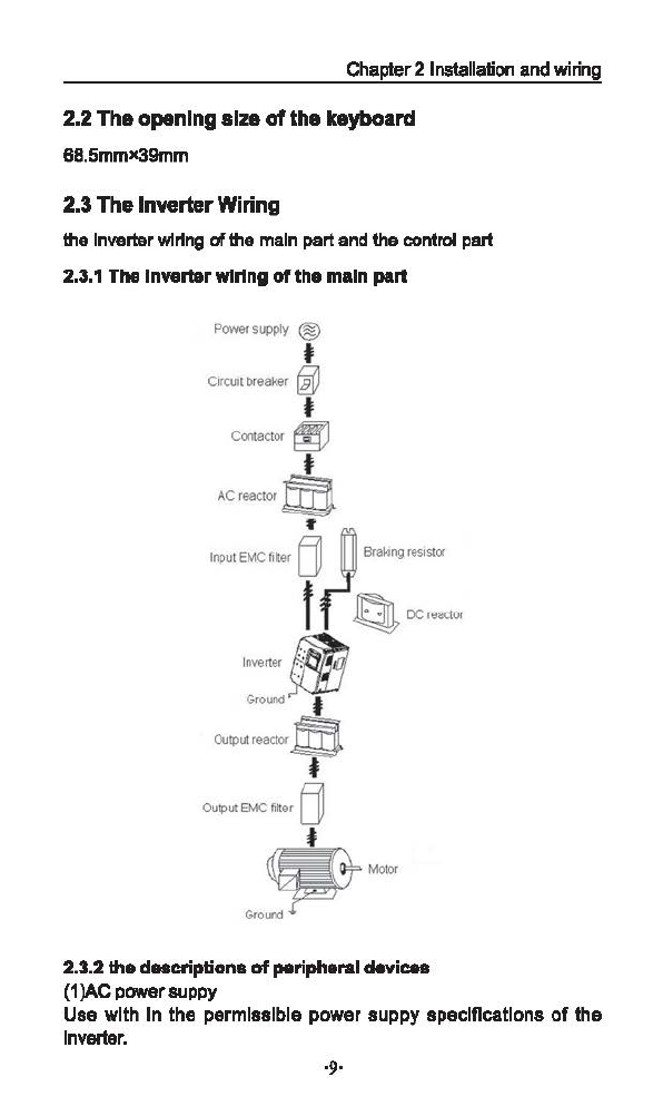
2.3TheInverterWiring
the Inverter
wlrfng
af
the
main
part
and
thecontrol part
2.3.1
The Inverterwiring
of
themain part
Powersupply ®
t
C~rcuot
br
eaker
~
t
Co.-.actor
~
t
ACreactor@
"
lnpu
l
EMC
file<
B
~
Braking
resostor
f(Q
0C••~LV
1
'=
f!P
Output
reactor
m
•
Mo
tor
2.3.2thedaacriptiona
of
paripbaraldaviC88
(1)AC powersuppy
Use with In the permissible power suppy speciOcatlons
of
the
In
verier.
Instruction
of
NZ2000 Series Inverter
(2)Moulded case circuit broaker:(MCCB)
When
the
power
supply
voltage
is
low
or
the
input
terminal
short
circuit
occurs,the
breaker
can
provide
protection,during
inspection,maintenance
or
the inverter is
not
running,you can cut
off
the breakerto separate the inverterfrom the power supply.
(3)Magnetic contractor{MC)
The contractor can tum on and tum offthe power
of
the inverter
to
ensure safety.
(4)AC current reactor
a suppress high harmonicto protect the inverter to ensure safety.
(5)Brake resistor
When
the
motor
is braking, the resistor can avoid DC
bus
high
voltage
of
the inverter ,and improve the braking ability
of
the internal
brake
unit
2.3.3 Precautions main
circuit
wiring
(1) circuit wiring ,refer to requirements
of
electrical codes.
(2)Application
of
supply
power
to
output
terminals(U,V,W)of
the
invert will damage it,so never perform such wiring.
(3)Power supply's wiring ,please use isolated wire and wire pipe
if
possible,and make isolated wire and wire pipe link to the earth.
(4)The inverter and welding device, high-power motor,high-power
load can't use a earth cable.
(5) The ground terminal E,ground impedance is lower than
1000
(6)Use
the
shortest earth cable possible.
(?)Many inverters are earthed, pay attention
not
to cause ground
loops.
(8)the power cables and the control cables
must
be separated
in
the main circuit. keep the power cables more than 10
em
awayfrom
the
paral!elled control cables,
when
the power cables
and
1he
control
cables are crossed,make them verticai.Don't make the power cables
and the control cables together,
or
the interference will cause.
(9}Under nonnal circumstances,the diatance between the inverters
and
the
motors
is
less
than
30m,the
current
produced
by
the
parasitic
capacitance
may
cause
over-current
protection,
mis-
action,inverter's fault and equipment operating faults .The maximum
distance is 100m,when the distance is long, please selectthe output
side filter,and reduce the carrierfrequency.
(10)Don't
install
an
absorbing
capacitor
or
other
capacitance-
resistance absorbing devices.
Chapter2 Installation and wiring
(11}Ensure
the
terminals
are
all
locked
tightly,the
cables
are
connected well with the terminals,present the looseness due
to
an
action
of
shaking,causesparks and the shortcircuit
To
minimize the interference,it is recommended that the contactor
and relayshould be connected
to
the surge absorber.
• Noisefilter installed at the input side
of
inverter;
• Install noise isolation for other equipment
by
means
of
isolation
transformer
or
powerfilter.
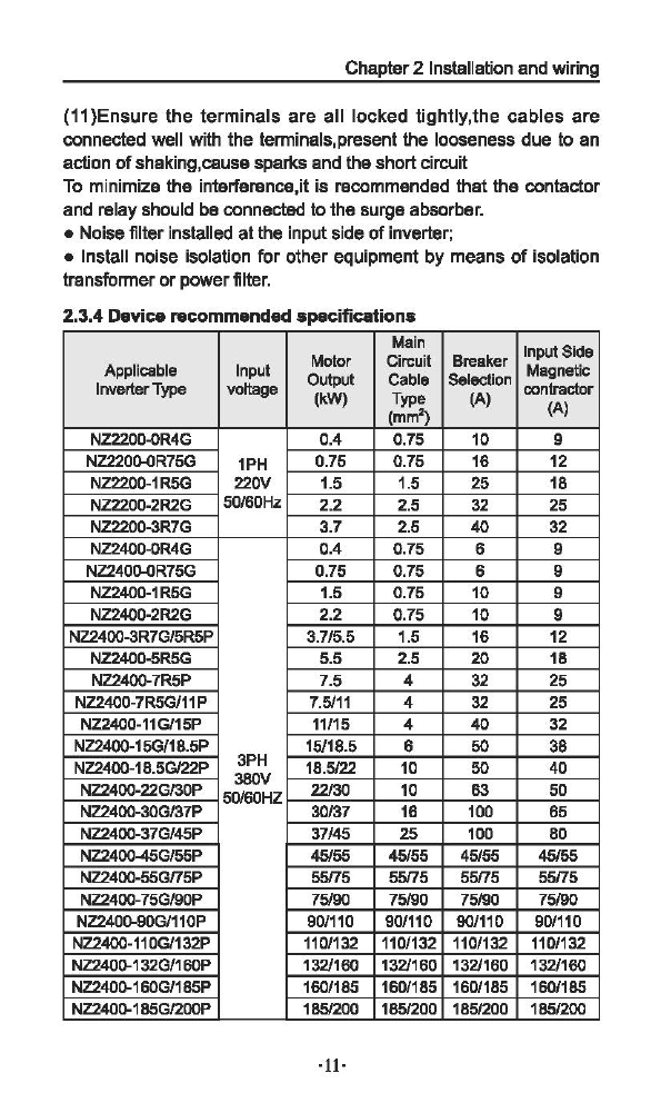
2.3.4 Deviceracommandad specifications
Main
Input Side
Motor Circuit Breaker
Applicable Input Output Cable Selection
Magne
tic
Inverter
Type
voltage (kW) Type (A) contractor
(mm")
{A)
NZ2200-0R4G 0.4 0.75
10
9
NZ220().()R75G
1PH
0.75 0.75
16
12
NZ2200-1R5G 220V 1.5 1.5 25 18
NZ2200-2R2G 50/60Hz 2.2 2.5
32
25
NZ2200-3R7G 3.7 2.5
40
32
NZ2400-0R4G 0.4 0.75 6 9
NZ240().()R75G
0.75 0.75 6 9
NZ2400-1R5G 1.5 0.75
10
9
NZ2400-2R2G 2.2 0.75
10
9
NZ2400-3R7G/5R5P 3.7/5.5 1.5
16
12
NZ2400-5R5G 5.5 2.5 20 18
NZ240Q-7R5P
7.5 4
32
25
NZ2400-7R5G/11P
7.5111
4
32
25
NZ2400-11G/15P
11/15
4 40
32
NZ2400-15G/18.5P
15118.5
6 50
38
NZ2400-18.5G/22P
3PH
18.5122
10
50
40
NZ2400-22GI30P 380V
22130
10
63
50
50/60HZ
NZ2400-30GI37P
30137
16
100
65
NZ2400-37G/45P 37/45
25
100
80
NZ2400-45G/55P
45155
45155
45155 45155
NZ2400-55G/75P
55175
55175
55175 55175
NZ2400-75GI90P
75190 75190
75190 75190
NZ240()..90GJ110P
901110
901110
901110
901110
NZ2400-11
OG/132P
1101132
1101132
110/132 110/132
NZ240Q-132G/160P
1321160
132/160 132/160
1321160
NZ240Q-160G/185P
160/185
1601185
1601185
160/185
NZ240Q-185GI200P
1851200 1851200
1851200
1851200
·11·
Operation Instruction
of
NZ2000 Series Inverter
Main
Input Side
Motor Circuit Breaker
Applicable Input Output Cable Selection
Magne
tic
Inverter
Type
voltage
(kW)
Type (A) contractor
(mm2) (A)
NZ2400-200GI220P
3PH
2001220
2001220
2001220
2001220
NZ2400-220G/250P 380V 220/250
2201250
2201250
220/250
50/60HZ
"The
above data are
for
reference only.
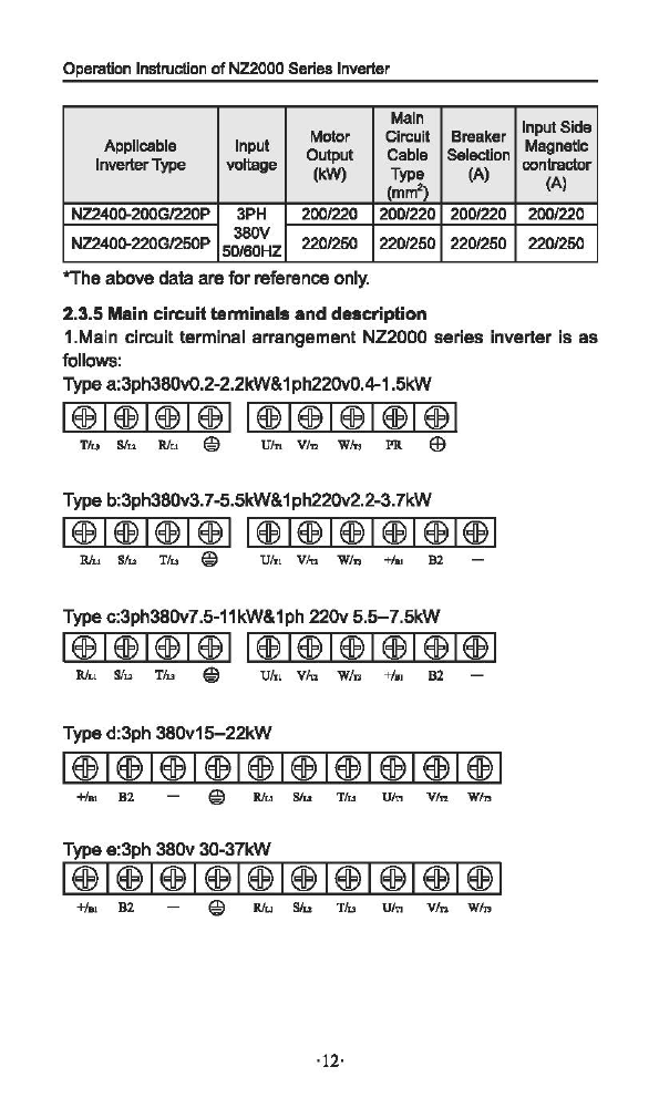
2.3.5 Main circuitterminals anddescription
1.Main circuit terminal arrangement
NZ2000
series
inverter
is
as
follows:
Typea:3ph380V0.2-2.2kW&1ph220V0.4-1 .5kW
1®1®1®1®11®1®1®1®1®1
Tiu
stu
Rlu @ Uin Vi.,
Wm
PR
ffi
Type b:3ph380v3.7-5.5kW&1ph220v2.2-3.
7kW
1®1®1®1®1
1®1®1®1®1®1®1
Rlu
SJu
Tlu
@
UIT1
Vm
Win
+/o1
B2
Typec:3ph380v7.5-11kW&1ph
220v
5.5-7.5kW
1®1®1®1®1
1®1®1®1®1®1®1
Rlu
S/u
Tlu @
U/T,
Vln
W/n +/.,
82
-
Typed:3ph
380v15-22kW
+J.,
82
@ Rlu
stu
Tlu
Uin
Vln
Win
Typee:3ph
380v
30-37kW
e Rlu Sfu
T/u
Uin
V/n
Win
·12·

Chapter
2 Installation
and
wiring
Typef:3ph
380v
45-75kW
1@1@1@1@1@1@1@1@1@1@1
R S
Te-+!.nB2U
VW
POWER MOTOR
Type
g:3ph
380v
90-110kW
R S T -
~
B2 U V W
POWER
M01UR
eo
Type h:3ph
380v
132-160kW
1@1@1@1@1@1
R S T
~
B2
POWER
-+1..82
u v w
M01UR
2.Description
of
main circuit terminals
Terminal Name
D~
lon
RIL
1,
S/l..2, T/L3 Connect to the commercial powersupply.
U/T1, U/T2,
UIT3
Inverteroutputterminals, connect a three-phase
motor.
+/B1, -Positive and negative
DC
inverter, brakeunit can
beconnected.
+/61,
B2
Connectbrake resistor.
+,
PR
@ Earth (ground)
3.Wiring Example
+/s1
B2
~
Rlu
Slu
Th,
U/n Vfn W/,
1~1~1!1'.!J~Ej'
1
1ml
·13·

Instruction
of
NZ2000 Series Inverter
4.The basicwiring diagram
Braking
resistor
{optional)
;---c::J---;
! !
>---<
RILl
+/Ill B1 u
owertmpply
:::
S/L2 v
w
T/L3 QlE
RA
r
RB
RC
Forwud/Ston -
''
FWD
"""""""""
' '
·----------~S:
Exccpti.onlllevcne ; '
REV
'
M-ulti-speed
eornn:wad
1o
Sl
Iligb-spced
puJ_::e
fugut
: S2 !
1Q:Q]
o n :MCM
S3 : V Fov I
Multi-speed
cciinn:iiuid
3i
iVhllll&'lli!ld!.1llre!l!:
S4
l-~-~-----l
FOV
' ' (0-10V/0-20mA}
Input signal
oomiiWU.'
'
GND
j_
E@
GND
-
~Q
"
Frequ.ency setting
JXlWer
!.
2 f
~
+lOV
lOmA(MAX)
RS-
I L
____
\_J
__
FIV{O-lOV)
FIC(0-10V/0-20m.A) RS-
GND
··--j_
!1rnO-J;----:
GND
!VFICI
!
i
Vbltap~wmmt
i
:.c.umt~-----~
2.4 Control Terminals
Control terminal arrangement
M)
""""
'"l,
Relay output
-
VDC/3A
250VAC/30
Multi-function
-
48VIX:f
SOmA
~Analog
<mtput
~
: tennlllill
' '
' '
...:....:--
j_
,-,
~
++Terminal
' '
Cmnnnmicetion
7-
Please Ulle shielded cable
1®1®1®1®1®1®1®1®1®1®1®1®1®1~®1®1
FWD
REV
Sl
S2
83
S4
lOV
FIV
FIC
GND
FOV
MCM
MOl
@.'D
RS-
RS1
1®1®1®1
RA
RB RC
This manual suits for next models
30
Table of contents


