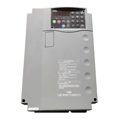
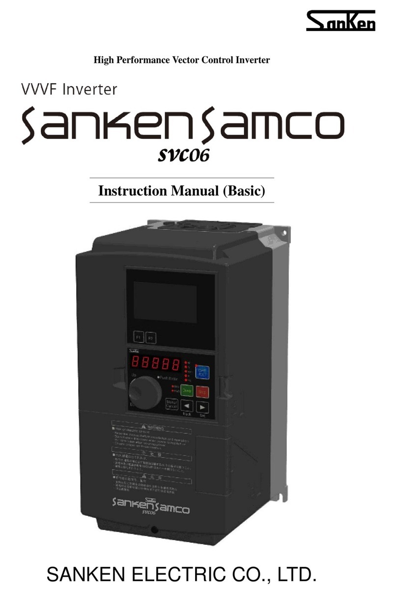
Sanken SVCO6 User manual

High Performance Vector Control Inverter
Instruction Manual
SANKEN ELECTRIC CO., LTD.


- 1 -
Thank you for purchasing the Sanken High Performance Vector Control Inverter SVC06 series.
This inverter is designed to drive an induction motor at a variable speed. The inverter has a built-in microprocessor
providing a wide range of functions and easy operability. To ensure many years of trouble-free operation and maintain
optimum performance, be sure to read through this manual before using the product.
[For Safe Use]
Safety instructions are given in this manual and on the product for safe use. Read the instructions thoroughly and
use it correctly before using this product.
After reading, keep this manual near to the machines for convenient reference.
Expressions and meanings of safety notes
Make sure the [safety notes] are fully read and correctly used prior to installation, operation, maintenance inspection.
Critical safety instructions are marked ―Danger‖ or ―Caution‖ as follows.
Danger
This symbol indicates a hazard that could lead to death or serious injury if the warning is
ignored and the product is handled incorrectly.
Caution
This symbol indicates a hazard that could lead to injury or damage to property if the warning is
ignored and the product is handled incorrectly.
Even ignoring an instruction marked ―Caution‖ can have serious consequences under some circumstances. Be sure
to abide by all instructions in this manual, irrespective of the degree of danger.
Meanings of symbols
This symbol indicates a potential danger.
The specific content of danger is indicated within . (This example indicates a general
danger.)
General danger
Electric shock
danger
Fire danger
This symbol indicates the need for caution.
The specific content of caution is indicated within . (This example indicates a general
caution.)
General caution
Caution: risk of
electric shock
Caution: risk of
rotating objects
This symbol indicates a prohibition (strictly prohibited).
The specific content of prohibition is indicated within . (This example indicates a
general prohibition.)
General
prohibition
Disassembly is
prohibited
The use of open
fire is
prohibited.
This symbol indicates an action that must be performed (the project that must be
performed).
The specific content is indicated within ●. (This example indicates a general
compulsory item.)
General
compulsory item
Must be
grounded

- 2 -
CONTENTS
1. Safety Notes...........................................................................................................................................- 5 -
1-1 Important Notes ......................................................................................................................- 5 -
1-2 Notes on Use ..........................................................................................................................- 5 -
1-3 Notes on Installation ...............................................................................................................- 6 -
1-4 Notes on Handling and Moving...............................................................................................- 6 -
1-5 Notes on Wiring ......................................................................................................................- 7 -
1-6 Notes on Operation.................................................................................................................- 8 -
1-7 Notes on Maintenance and Inspection ...................................................................................- 9 -
1-8 Disposal ..................................................................................................................................- 9 -
1-9 Others .....................................................................................................................................- 9 -
2. Checking the Product and Precautions on Use...................................................................................- 10 -
2-1 Checking the Product............................................................................................................- 10 -
2-2 The Contents of the Model....................................................................................................- 10 -
2-3 Precautions on Use............................................................................................................... - 11 -
2-4 Names of Parts.....................................................................................................................- 12 -
3. Installation............................................................................................................................................- 13 -
3-1 Installation Location and Storage..........................................................................................- 13 -
3-2 Installation Direction and Space ...........................................................................................- 16 -
3-3 Removal and Installation of the Front Cover ........................................................................- 17 -
3-3-1 Small-Capacity Model (SVC06-0015~0075-**2/SVC06-0007~0150-**4).....................- 17 -
3-3-2 Middle-Capacity Model (SVC06-0185~0750-**4) .........................................................- 18 -
3-3-3 Large-Capacity Model (SVC06-0900~2500-**4)...........................................................- 19 -
3-4 Removal and Installation of the Operation Panel .................................................................- 20 -
3-4-1 Removal of Operation Panel.........................................................................................- 20 -
3-4-2 Installation of Operation Panel......................................................................................- 20 -
4. Wiring...................................................................................................................................................- 21 -
4-1 Connection with Peripheral Devices.....................................................................................- 21 -
4-2 About Wiring .........................................................................................................................- 22 -
4-3 Terminal Connection Diagram ..............................................................................................- 24 -
4-4 Composition of Main Circuit Terminals .................................................................................- 26 -
4-4-1 Description of Main Circuit Terminals............................................................................- 26 -
4-4-2 Connection Diagram of Main Circuit Terminals.............................................................- 26 -
4-4-3 External Brake Resistor Selection Example .................................................................- 27 -
4-4-4 Capacities of MCCB and MC and Wire Size.................................................................- 29 -
4-4-5 Molded Case Circuit Breaker (MCCB) Selection Example...........................................- 31 -
4-5 Composition of Control Circuit Terminals..............................................................................- 32 -
4-5-1 Wire Size and Terminal Arrangement............................................................................- 32 -
4-5-2 Functions of Control Circuit Terminals ..........................................................................- 33 -
4-5-3 Multifunctional Input / Output ........................................................................................- 36 -
4-5-4 Control Logic Switching.................................................................................................- 37 -
4-5-5 Connection of Control Circuit Terminals........................................................................- 38 -
4-5-6 Communication Function Terminal................................................................................- 41 -
4-5-7 Connection of PG Sensor .............................................................................................- 42 -
4-6 Installation and Wiring of Optional Board .............................................................................- 43 -
4-6-1 Overview of Optional Board ..........................................................................................- 43 -
4-6-2 Installation Method of Optional Board...........................................................................- 43 -
4-6-3 Auxiliary Power Supply Option......................................................................................- 43 -
4-7 About EMC Filter...................................................................................................................- 44 -

- 3 -
Chapter 14
Chapter 1
Chapter 2
Chapter 3
Chapter 4
Chapter 5
Chapter 6
Chapter 7
Chapter 8
Chapter 9
Chapter10
Chapter11
Chapter12
Chapter13
5. Operation Panel ...................................................................................................................................- 45 -
5-1 Names and Functions of Parts of the Operation Panel ........................................................- 45 -
5-1-1 LCD Display Part...........................................................................................................- 46 -
5-1-2 LCD Operation Part.......................................................................................................- 46 -
5-1-3 LED Display Part...........................................................................................................- 46 -
5-1-4 LED Operation Part.......................................................................................................- 46 -
5-2 Switching of Statuses............................................................................................................- 47 -
5-3 Status Display Mode.............................................................................................................- 48 -
5-3-1 Version Display..............................................................................................................- 48 -
5-3-2 Inverter Status Mode.....................................................................................................- 48 -
5-3-3 Alarm Display................................................................................................................- 50 -
5-3-4 Command Setting..........................................................................................................- 51 -
5-4 Function Code Display Mode................................................................................................- 53 -
5-4-1 Status Transition Diagram.............................................................................................- 53 -
5-4-2 Basic Operation.............................................................................................................- 54 -
5-4-3 Confirming Operation....................................................................................................- 55 -
5-4-4 Signed Operation ..........................................................................................................- 56 -
5-5 Special Functions..................................................................................................................- 57 -
5-5-1 Copy Function Operation ..............................................................................................- 57 -
5-5-2 Changed Code Display Operation ................................................................................- 58 -
5-5-3 Function Code Initialization Operation..........................................................................- 59 -
5-5-4 Alarm Contents Reading Operation ..............................................................................- 60 -
5-5-5 Alarm Status Confirmation Operation............................................................................- 61 -
5-5-6 Serial Number Display...................................................................................................- 62 -
5-5-7 7-Segment Monitor Display List ....................................................................................- 63 -
5-6 Connecting Operation Panel with Extension Cable..............................................................- 64 -
6. Operation .............................................................................................................................................- 65 -
6-1 Operation Steps ....................................................................................................................- 66 -
6-2 Test Run................................................................................................................................- 67 -
6-2-1 Confirmation Before Power Input..................................................................................- 67 -
6-2-2 Confirmation After Power Input .....................................................................................- 67 -
6-2-3 Basic Setting (1)............................................................................................................- 68 -
6-2-4 Motor Control Setting ....................................................................................................- 68 -
6-2-5 Basic Setting (2)............................................................................................................- 69 -
6-2-6 Motor Parameter Auto Tuning .......................................................................................- 69 -
6-2-7 Basic Setting (3)............................................................................................................- 74 -
*Both of ON and OFF will be the same operation.......................................................................- 75 -
6-2-8 Operation Confirmation.................................................................................................- 75 -
6-3 Special Functions..................................................................................................................- 79 -
6-3-1 JOG Operation..............................................................................................................- 79 -
6-3-2 Hold Operation ..............................................................................................................- 79 -
6-3-3 Notes on Free Run Stop Terminal (MBS)......................................................................- 80 -
6-4 Definition of Technical Terms................................................................................................- 83 -
7. Function Code......................................................................................................................................- 84 -
7-1 Representation and Description of Function Codes.............................................................- 84 -
7-2 Function Code List................................................................................................................- 85 -
7-3 Description of Functions .....................................................................................................- 103 -
7-4 Serial Communication Function..........................................................................................- 256 -
7-4-1 Outline.........................................................................................................................- 256 -
7-4-2 Terminal Functions and Wiring....................................................................................- 257 -
7-4-3 Inverter Operation and Related Function Code Setting by Serial Communication.....- 258 -
7-4-4 Communication with Dedicated Protocol (SANKEN Communication Protocol)..........- 260 -
7-4-5 Programming Design...................................................................................................- 262 -

- 4 -
7-4-6 Modbus-RTU Communication.....................................................................................- 279 -
8. Protection & Error Function................................................................................................................- 290 -
8-1 Operation Error...................................................................................................................- 290 -
8-1-1 List of Error Operation.................................................................................................- 291 -
8-2 Conflict & Interference Error ...............................................................................................- 292 -
8-2-1 List of Conflict & Interference Error.............................................................................- 292 -
8-3 Warning Status....................................................................................................................- 295 -
8-3-1 List of Warnings...........................................................................................................- 295 -
8-4 Alarm Status........................................................................................................................- 296 -
8-4-1 List of Alarms...............................................................................................................- 296 -
9. Fault Analysis.....................................................................................................................................- 299 -
10. Maintenance & Inspection...........................................................................................................- 300 -
10-1 Precautions on Checking and Maintenance.......................................................................- 300 -
10-2 Inspection Items..................................................................................................................- 300 -
10-3 Part Replacement...............................................................................................................- 302 -
10-3-1 Fan Replacement........................................................................................................- 302 -
10-3-2 Smoothing Capacitors.................................................................................................- 306 -
10-4 Megger Test ........................................................................................................................- 306 -
10-5 Electrical Measurement of Main Circuit..............................................................................- 307 -
11. Specification................................................................................................................................- 308 -
11-1 Standard Specification ........................................................................................................- 308 -
11-2 Inverter General Specification.............................................................................................- 312 -
11-3 Communication Function Specification...............................................................................- 313 -
11-4 Storage Environment ..........................................................................................................- 313 -
12. External Dimension.....................................................................................................................- 314 -
12-1 Master Dimension...............................................................................................................- 314 -
12-2 Operation Panel Dimension................................................................................................- 317 -
12-3 DC Reactor Dimension.......................................................................................................- 318 -
13. Peripheral Equipments & Options...............................................................................................- 319 -
14.EC Directives...............................................................................................................................- 321 -

- 5 -
Chapter 1
1. Safety Notes
1-1 Important Notes
Danger
Caution: risk of electric shock
It is absolutely prohibited to remove the cover
The risk of casualties exists because there are high-voltage circuits inside, accidental touch of which
would cause electric shock.
Caution: Fire Hazard!
Immediately stop the device when peculiar smell, abnormal noise, smoke or sparks, etc. are found in
the device (turn the power switch to "off" position), and then set the input side circuit breaker which is
set outside to OFF. And contact the sale store or business office of the Company where the device is
purchased.
In case of a fire, please use extinguisher for electrical fire (dry powder), but do not use water for fire
fighting.
1-2 Notes on Use
Caution
Before starting the inverter, confirm the safety status of the load first, and then start running
operation following the instruction manual.
Arbitrary power-on has the risk of accidents such as electric shock etc.
Do not smoke or use fireworks around the inverter.
As the explosions and damage may result in personal injury and fire.
Do not keep containers which contain water such as vase etc. above the equipment.
In case the vase is overturned, the water flowing out will penetrate inside the device and cause fire.
Do not sit or stand on top of the equipment, and do not lean on it or treat it as a footboard.
Otherwise, personal injury may be caused by overturn of the equipment.
Do not insert sticks, fingers etc. into the fan.
Because the rotating fan would cause personal injury.
During operation, do not short-circuit the input terminal and output terminal.
As the current return will result in electric arc, the arc light can cause personal burns and visual
impairment.
Its use in the following applications is absolutely prohibited.
a) Medical equipment which are directly related to life.
b) Trolley buses which may lead to personal injury.
c) Important computer systems for the community, public utilities.
d) Equipment with these as standards.
When used in the above-mentioned load equipment, please consult the Company in advance. For
equipment which have significant impact on personal safety and the maintenance of public functions,
special measures are required on the use, maintenance and management, such as multiple of the
system, setting up generating equipment for emergency use etc..

- 6 -
1–3 Notes on Installation
1-3 Notes on Installation
Caution
It is absolutely prohibited to store or use the inverter under the environmental conditions
described below.
Failure to observe this warning may result in a fault, damage, or deterioration, which could lead to fire.
Place becoming high temperature, low temperature, and high humidity out of the environmental
conditions specified in the instruction manual.
In direct sunlight.
Near a heater or other heat source.
In a location subject to vibration or physical shock.
Near machinery that generates sparks
In a location subject to dust, corrosive or inflammable gases, salt, and water droplets.
Outdoors.
Higher than 2000 meters above sea level.
Other similar environments.
Mount the inverter on a metal surface or other non-flammable surface.
Failure to observe this warning may result in a fire.
Install the inverter in a location that can bear its weight.
Failure to observe this warning may result in injury if the inverter falls down.
Do not plug up the air inlet/exhaust. (Refer to ―Installation‖ in the instruction manual for
implementation).
If the air inlet/exhaust is blocked, a fire may be resulted due to internal temperature rise of the
equipment.
Do not place the inverter near flammable materials.
Failure to observe this warning may result in a fire.
Do not allow foreign objects into the inverter or attach to the cooling fans.
Failure to observe this warning may result in a fire or an accident.
Do not operate an inverter which is damaged, lacking parts or dented.
Failure to observe this warning may result in an electric shock, injury, fire or accident.
1-4 Notes on Handling and Moving
Caution
During handling and moving, do not tilt the equipment.
Otherwise, personal injury may be resulted due to falling down of equipment.
Prior to handling and movement, confirm the weight marking attached to the equipment first, if
necessary, please prepare alternative handling machine for work.
Failure to observe this warning may result in personal injury.
Do not fumigate wood packagings which need to disinfect.
Because that Volatile gases and vapors may cause deterioration of electronic components.

- 7 -
Chapter 1
1–5 Notes on Wiring
1-5 Notes on Wiring
Danger
Wiring must be performed by qualified personnel.
Failure to observe this warning may result in an electric shock or fire due to incorrect wiring.
Do not connect AC power to an output terminal (U, V, or W).
Failure to observe this warning may result in personal injury or fire.
Do not use if rated voltage is exceeded.
Failure to observe this warning may result in personal injury or fire.
Do not connect a resistor directly to the DC terminals (Pand X).
Failure to observe this warning may result in a fire.
Connection between the ground terminals must be reliable.
Failure to observe this warning may result in electric shock if ungrounded.
For the thickness of grounding wires, please refer to the wire sizes specified in the instruction manual.
Please tighten the terminal block screws according to specified tightening torques.
Failure to observe this warning may result in a fire.
Check that the AC power supply voltage is equal to the rated voltage of the inverter.
Failure to observe this warning may result in personal injury or fire.
For cable types and diameters, please use the cables specified in the instruction manual.
Failure to observe this warning may result in heating or a fire if the diameters of wires are too small.
Secure the inverter before wiring.
Failure to observe this warning may result in electric shock or personal injury.
Caution
The inverter, motor or wiring may cause interference. Please note misoperation of peripheral
devices.
Failure to observe this warning may result in accidents.
If a Residual Current-operated protective Device (RCD) is to be used, it must be an RCD type B.
If the input and output are terminal blocks, the wire heads must be connected with crimp
terminals.
Failure to observe this warning may result in electric shock or fire.

- 8 -
1–6 Notes on Operation
1-6 Notes on Operation
Danger
Attach the front cover before turning the power on.
And, do not remove the front cover when the power is on.
Failure to observe this warning may result in electric shock.
Do not touch any switch with wet hands.
Failure to observe this warning may result in electric shock.
Do not touch any inverter terminal when the inverter is energized even if the motor is not
operating.
Failure to observe this warning may result in electric shock.
Do not get close to the machinery driven by the inverter after an alarm stop because it will
restart suddenly if the restart function is selected. (Design the system to ensure personal safety
at restart.)
Failure to observe this warning may result in personal injury.
Provide a separate emergency stop switch.
Failure to observe this warning may result in personal injury.
If alarm reset is done in the operation signal status, the equipment will restart suddenly.
Therefore, please cut off the operation signal before releasing an alarm.
Failure to observe this warning may result in personal injury.
Caution
Do not touch the radiator fins or DC reactor because they become very hot.
Failure to observe this warning may result in burns.
It is easy to set the inverter drive speed from low to high, so be sure to confirm the operating
range of the motor and machinery driven by the inverter before making such settings.
Failure to observe this warning may result in personal injury.
Please set separate brake if it is required to keep brake.
Failure to observe this warning may result in personal injury.
Do not start or stop the inverter by turning the main circuit ON or OFF.
Failure to observe this warning may result in equipment faults.

- 9 -
Chapter 1
1–7 Notes on Maintenance and Inspection
1-7 Notes on Maintenance and Inspection
Caution
Works such as maintenance, inspection and replacement of parts etc. can only be carried out by
professional electricians.
[Take off any metal item (such as watch, bracelet, etc.) before working on the equipment.]
[Use insulated tools.]
Failure to observe this warning may result in electric shock or burns.
Turn off the input power for maintenance or inspection. After the CHARGE lamp goes out,
check that the voltage between DC terminals Pand X is less than 30 VDC.
Failure to observe this warning may result in electric shock or personal injury.
1-8 Disposal
Caution
When disposing this product, please entrust a specialized industrial waste disposal service (*) to
handle.
If not handled by professionals, personal injury may be caused by capacitor explosion or harmful
gases produced in explosion.
(*)So-called professional waste disposal service refers to the [Industrial Waste Recycling and
Carrying Body] and [Industrial Waste Disposal Body]. Those who carry out recycling, handling and
disposal of industrial waste without prior approval will be subject to legal action.
([Subject to laws regarding disposal and cleaning of industrial products])
1-9 Others
Danger
Reformation of the product without authorization is strictly prohibited.
Failure to observe this warning may result in an electric shock, personal injury, fault, damage or fire.
This product is designed for operation of a three-phase induction motor. Therefore it can not be
used for single-phase motor or other purposes.
Failure to observe this warning may result in a fire or an accident.
Do not use this product for life-support equipment, or other purposes directly related to dangers
to people.
Failure to observe this warning may result in an accident.
Install a safety device when this product is applied to facilities where the failure of this product
may cause a serious accident or damage.
Failure to observe this warning may result in an accident.

- 10 -
2. Checking the Product and Precautions on Use
2-1 Checking the Product
After unpacking the product, check the following:
Check that the product has not been damaged during delivery, such as depression of casing etc..
If such problems are found, please contact the retailer.
Danger
Do not use if rated voltage is exceeded.
Failure to observe this warning may result in personal injury or fire.
Check that the AC power supply voltage is equal to the rated voltage of the inverter.
Failure to observe this warning may result in personal injury or fire.
Product body
Warning identification
(Below SVC06-0040)
Warning identification
Rating nameplate
Figure 2-1 Outside View
Instruction Manual
This manual
2-2 The Contents of the Model
The model on the nameplate
SVC06 ―0015 -NN4
〔Capacity〕
0015:1.5kW-150% / 2.2kW-120%
0055:5.5kW-150% / 7.5kW-120%
0110:11kW-150% / 15kW-120%
0185:18.5kW-150% / 22kW-120%
0370:37kW-150% / 45kW-120%
0550:55kW-150% / 75kW-120%
0900:90kW-150% / 110kW-120%
1320:132kW-150%/160kW-120%
2000:200kW-150%/250kW-120%
〔Series Name〕
〔Operation panel〕
N: Without LCD panel
※Operation panel with LCD panel is optional.
〔Voltage Class〕
4: 3φ-400V class
2: 3φ-200V class
〔EMC filter〕
F: Configuration
N: no

- 11 -
Chapter 2
2-3 Precautions on Use
1. Use the product in a location satisfying the standard environmental specifications (temperature,
humidity, vibration, dust, water drop, and toxic gases etc.).
2. Before starting up the product for the first time, carefully check the wiring. Make sure that the power
cable (input) and motor cable (output) are connected correctly. Otherwise, the inverter will be damaged.
3. Since the ambient temperature of the installation location greatly affects the life of the inverter, it is
recommended to lower the ambient temperature before operation.
4. When installing the product in an enclosure, check the closure size and ensure sufficient ventilation.
5. Capacitors and surge suppressors used for improving the inverter's output power factor may be heated
or even damaged because of high-order harmonic components output by the inverter. In addition, when
current overload occurs in the inverter, over-current protection action will be automatically executed.
Therefore, please do not connect capacitors and surge suppressors at the output side of the inverter. To
improve power factor, install the DC reactor at the DC side or AC reactor at the primary side (i.e. input
end) of the inverter.
6. When implementing a megger test, follow the method given in this instruction manual (10-4 ―Megger
Test.‖).
7. When using earth leakage circuit breaker protection switch, select a product for corresponding
high-order harmonic and surge.
8. Please connect directly in principle between the inverter and motor. If you have, such as using a
transformer between the inverter and motor, there is a possibility that an excessive current flow, such as
an inverter / motor may be damaged.
9. Avoid inserting a electromagnetic contactor between the inverter and the motor. If the electromagnetic
contactor is turned on and off while the inverter is operating, an excess current will be generated.
10. Select larger capacity since the operating characteristics of full electromagnetic-type MCCB changes
with higher harmonic current.

- 12 -
2-4 Names of Parts
2-4 Names of Parts
Figure 2-2 Names of Parts
Table 2-1 Names of Parts
No.
Name
Function
1
LCD display part
Refer to [Chapter 5 Operation Panel]
2
Operation Panel
Refer to [Chapter 5 Operation Panel]
3
Wiring Hole
Refer to [Chapter 4 Wiring]
4
Air Inlet
Cooling air suction hole
5
Exhaust hole (fan)
Cooling air exhaust hole
[Top View]
[Bottom View]
①
②

- 13 -
Chapter 3
3. Installation
3-1 Installation Location and Storage
This equipment is an electronic control device. Please pay full attention to environment of the device before it is
used.
Caution
Mount the inverter on a metal surface or other non-flammable surface.
Failure to observe this warning may result in a fire.
Do not plug up the air inlet / exhaust hole.
If the air inlet/exhaust is blocked, a fire may be resulted due to internal temperature rise of the device.
Do not place the device near flammable materials.
Failure to observe this warning may result in a fire.
Do not install the device where larger vibration exists.
Otherwise, personal injury may be caused due to falling of the mainframe.
It is absolutely prohibited to store or use the inverter under the environmental conditions
described below.
Failure to observe this warning may result in a fault, damage, or deterioration, which could lead to fire.
In direct sunlight.
Near a heater or other heat source.
In a location subject to vibration or physical shock.
Near machinery that generates sparks
In a location subject to dust, corrosive or inflammable gases, salt, and water droplets.
Outdoors.
Higher than 2000 meters above sea level.
Other similar environments.
Table 3-1 Work Environment Parameters Table 3-2 (1) Capacity Modes
Ambient
temperature
Mode A(150% 1min)
-10℃-50℃
Mode B(120% 1min)
-10℃-40℃
Relative
humidity
Below 95%RH (no frost)
Vibration
Below 5.9m/s2(0.6G)
Working
environment
Below 2000m above sea level
(When above 1000m, the current will be
reduced for use)
Working
place
Indoor
(free from corrosive and flammable gases,
oil mist, and dust)
Capacity
Mode A
Mode B
0007
0.75kW (150%)
1.5kW (120%)
0015
1.5kW (150%)
2.2kW (120%)
0022
2.2kW (150%)
4.0kW (120%)※1
0037
3.7 kW (150%)
5.5kW (120%)
0040
4.0kW (150%)
5.5kW (120%)
0055
5.5kW (150%)
7.5 kW (120%)
0075
7.5kW (150%)
11kW (120%)
0110
11kW (150%)
15kW (120%)
0150
15kW (150%)
18.5kW (120%)
0185
18.5kW (150%)
22kW (120%)
0220
22kW (150%)
30kW (120%)
0300
30kW (150%)
37kW (120%)
0370
37kW (150%)
45kW (120%)
0450
45kW (150%)
55kW (120%)
0550
55kW (150%)
75kW (120%)
0750
75kW (150%)
90kW (120%)

- 14 -
3-1 Installation Location and Storage
Table 3-2 (2) Capacity Modes
※1: In 200V class, this is 3.7kW (120%).
Table 3-3 Storage Environment
Storage
temperature
-20℃-+65℃
This temperature is for short periods, such as during transportation.
Ambient temperature must be 30°C or lower for more than 3 months of storage in consideration of
the deterioration of the electrolytic capacitor.
Relative
humidity
Below 95%RH (no frost)
Storage
environment
Places free of direct sunlight, corrosive or inflammable gases, oil mist, dust, steam, water droplet,
vibration, or high salinity.
Table 3-4 Main body mounting screws
200V class
Capacity
Screws
Recommended Screw Tightening Torque
SVC06-0015-2
M4
1.5N•m
(1-1.9N•m)
SVC06-0037-2
SVC06-0075-2
M5
2.9N•m
(1.6-3.5N•m)
400V class
Capacity
Screws
Recommended Screw Tightening Torque
SVC06-0007-4
M4
1.5N•m
(1-1.9N•m)
SVC06-0015-4
SVC06-0022-4
SVC06-0037-4
SVC06-0055-4
M5
2.9N•m
(1.6-3.5N•m)
SVC06-0075-4
SVC06-0110-4
SVC06-0150-4
SVC06-0185-4
M5
2.9N•m
(1.6-3.5N•m)
SVC06-0220-4
SVC06-0300-4
Capacity
Mode A
Mode B
0900
90kW (150%)
110kW (120%)
1100
110kW (150%)
132kW (120%)
1320
132kW (150%)
160kW (120%)
1600
160kW (150%)
200kW (120%)
1850
185kW (150%)
220kW (120%)
2000
200kW (150%)
250kW (120%)
2200
220kW (150%)
280kW (120%)
2500
250kW (150%)
315kW (120%)

- 15 -
Chapter 3
3-1 Installation Location and Storage
Capacity
Screws
Recommended Screw Tightening Torque
SVC06-0370-4
M6
4.3N•m
(2.3-5.6N•m)
SVC06-0450-4
SVC06-0550-4
M8
10.8N•m
(5.4-13.8N•m)
SVC06-0750-4
SVC06-0900-4
M12
42N•m
(35-50N•m)
SVC06-1100-4
SVC06-1320-4
SVC06-1600-4
SVC06-1850-4
SVC06-2000-4
SVC06-2200-4
SVC06-2500-4

- 16 -
3-2 Installation Direction and Space
(1) This inverter is of the wall mounting type.
(2) Install the inverter vertically on a flat mounting surface.
(3) Since the inverter generates heat, provide adequate space around it to ensure good heat dissipation
conditions.
(4) When installing the inverter in a control cabinet, provide a ventilation fan to keep the ambient temperature
below 40°C.
(5) When installing the inverter in a control cabinet, mounting the radiator fins outside the control cabinet will
help to reduce the internal temperature of the cabinet.
(6) This inverter is of IP20 structure.
Please select according to intended use.
Figure 3-1 Surrounding Space Figure 3-2Arranging method of radiator fins outside the cabinet
When several inverters are set in a control cabinet, be sure to locate the ventilation fans properly to
allow free air circulation.
If the ventilation fans are located improperly, the ambient temperature will rise and affect the cooling
of the inverter.
Ven
Inside cabinet Inside cabinet Inside cabinet Inside cabinet
(Correct) (Incorrect) (Correct) (Incorrect)
Figure 3-3 Arranging method inside the cabinet Figure 3-4 Ventilation fan position in cabinet
Above 10cm
Above 10cm
Above 5cm
Above 5cm
Ventilation fan
Ventilation fan
Cooling air
Cooling air

- 17 -
Chapter 3
3-3 Removal and Installation of the Front Cover
3-3-1 Small-Capacity Model (SVC06-0015~0075-**2/SVC06-0007~0150-**4)
(1) Removal of front cover (lower)
Unscrew the M4 screws, and pull the cover toward you while pressing the Dent portion on both sides of the front
cover (lower).
Please carry out this work during the main circuit wiring, control circuit wiring, and SW1 switching.
M4 Screw
Press the snaps on Dent portion
Terminal block for
control circuit
Input/output
terminal block
Figure 3-5 Removal of front cover (lower)
(2) Removal of front cover (upper)
After the front cover (lower) has been removed, pull the cover toward you while pressing the Dent portion on both
sides of the front cover (upper).
Please carry out this work during the control circuit wiring (RX and TX), installation and removal of optional
boards, and SW2 switching.
Figure 3-6 Removal of front cover (upper)
Terminal block
for control
circuit (RX, TX)
Slots for optional
boards
Press the convex

- 18 -
3-3 Removal and Installation of the Front Cover
(3) Installation
When installing, work in reverse order.
3-3-2 Middle-Capacity Model (SVC06-0185~0750-**4)
(1) Removal of front cover (lower) and internal sealing plate (iron)
Unscrew the M4 screw on the front cover (lower) and pull down gently, and then the front cover (lower) will be
removed. Then, unscrew 4 M4 screws and remove the sealing plate.
Please carry out this work during the main circuit wiring, control circuit wiring, and SW1 switching.
Figure 3-7 Removal of front cover (lower) and internal sealing plate (iron)
(2) Removal of front cover (upper)
After the front cover (lower) has been removed, unscrew 2 M4 screws on the front cover (upper), and gently push up
front cover (upper), it will be removed.
Please carry out this work during the control circuit wiring (RX and TX), installation and removal of options,
and SW2 switching.
Figure 3-8 Removal of front cover (upper)
(3) Installation
When installing, work in reverse order.
Terminal
block
for control
circuit
Input / output terminal block
M4 screw
Slots for
optional boards
Terminal block for
control
circuit (RX, TX)
Table of contents
Other Sanken Inverter manuals
Popular Inverter manuals by other brands

We Care Solar
We Care Solar Suitcase WCS200 user manual

Nupower
Nupower NPEGG2400 manual

DAB
DAB MCE-22/P Instruction for installation and maintenance

Bryant
Bryant HOME STANDBY-40 ASPAS1BBL040 Specifications

Heat Controller
Heat Controller VMH 09 SD Installation, operation & maintenance manual

AVAG-Pumpen
AVAG-Pumpen Sirio owner's manual

Rheem
Rheem Solar Controller Kit installation instructions

Jiangsu GoodWe Power Supply Technologu Co.
Jiangsu GoodWe Power Supply Technologu Co. SS series user manual

Solarfox
Solarfox 2020 Series installation instructions

Fimer
Fimer UNO-DM-6.0-TL-PLUS-Q product manual

EG4
EG4 8KEXP-240V user manual

Zamp Solar
Zamp Solar ZS-30AD user manual