GRIDFREE LIFESTYLE KIT User manual

1
- LITHIUM
Lifestyle Kit Manual Hybrid 2022.indd 1Lifestyle Kit Manual Hybrid 2022.indd 1 3/08/22 4:52 PM3/08/22 4:52 PM

2
LIFESTYLE KIT - HYBRID - LITHIUM
x6
Installation of this kit legally requires an electrician.
We are always happy to help guide you through the install, troubleshoot, and answer any questions.
We recommend reading these instructions in full prior to starting your install.
Lifestyle Kit Manual Hybrid 2022.indd 2Lifestyle Kit Manual Hybrid 2022.indd 2 3/08/22 4:52 PM3/08/22 4:52 PM

3
1x 35mm² Cable 1m Pre-Crimped (Red+Black)
1x 16mm² Cable (Black) 1m Pre-Crimped (Red + Black)
1x Customized MCB Enclosure
1x 200A MCCB
4x Leader Fuse Holder
4x Leader Fuse
2x 6mm ² Solar PV Cable pair 10m - MC4
(Female, Red + Male, Black)
1x Battery Communications Cable
Lifestyle Kit Manual Hybrid 2022.indd 3Lifestyle Kit Manual Hybrid 2022.indd 3 3/08/22 4:53 PM3/08/22 4:53 PM

4
1x Growatt 5KW ES Hybrid Inverter
6x Growatt ARK LiFePO4 y 2.56kWh Battery
x6
2x DC Isolator
1x Solar Combiner Terminal Block
1x Growatt ARK Battery Base
Lifestyle Kit Manual Hybrid 2022.indd 4Lifestyle Kit Manual Hybrid 2022.indd 4 3/08/22 4:53 PM3/08/22 4:53 PM

5
12x PERC MONO Solar Panel
Lifestyle Kit Manual Hybrid 2022.indd 5Lifestyle Kit Manual Hybrid 2022.indd 5 3/08/22 4:53 PM3/08/22 4:53 PM

6
000 000 000
0000 000 000
ON I
OFF O
PV ARRAY
DC ISOLATOR
SISO SWITCH
IP66
ON I
OFF O
PV ARRAY
DC ISOLATOR
SISO SWITCH
IP66
10X38 ZTPV-25X10X38 ZTPV-25X 10X38 ZTPV-25X10X38 ZTPV-25X 10X38 ZTPV-25X10X38 ZTPV-25X 10X38 ZTPV-25X10X38 ZTPV-25X
7
4
5
5
Generator/ Mains Input
Mains Distribution Box
2x DC Isolator
Communication Cable
200A Breaker
4x Leader Fuse
Solar Combiner Terminal Block
4
5
5
6
7
6
Lifestyle Kit Manual Hybrid 2022.indd 6Lifestyle Kit Manual Hybrid 2022.indd 6 3/08/22 4:53 PM3/08/22 4:53 PM

7
1Start by creating two sets of six panels wired together. Connect the positive terminal of one panel
to the negative terminal of the next panel for each string.
Lifestyle Kit Manual Hybrid 2022.indd 7Lifestyle Kit Manual Hybrid 2022.indd 7 3/08/22 4:53 PM3/08/22 4:53 PM

8
000 000 000
0000 000 000
ON I
PV ARRAY
DC ISOLATOR
SISO SWITCH
IP66
ON I
PV ARRAY
DC ISOLATOR
IP66
SISO SWITCH
OFF O
OFF O
2Run the 6mm²solar cables from the solar panels to the DC isolators, and cut it to length.
Run the solar cables to the DC
isolators, and cut it to length.
Lifestyle Kit Manual Hybrid 2022.indd 8Lifestyle Kit Manual Hybrid 2022.indd 8 3/08/22 4:53 PM3/08/22 4:53 PM

9
3Use wire strippers to strip the ends off the black and red 6mm²solar cables. Strip the cables to
approximately 7mm in length.
7mm
4Ensure you use the correct metal crimp conductor, with the correct housing. Above
demonstrates how each wire connects to its solar connector. The positive wire uses “Metal
conductor A” and “Solar connector housing A”, the negative wire uses “Metal conductor B”
and “Solar connector housing B”.
Metal conductor B.
Metal conductor A.
Solar connector
housing B.
Solar connector
housing A.
Gland nut (same for
both wires).
AB
Lifestyle Kit Manual Hybrid 2022.indd 9Lifestyle Kit Manual Hybrid 2022.indd 9 3/08/22 4:53 PM3/08/22 4:53 PM

10
6
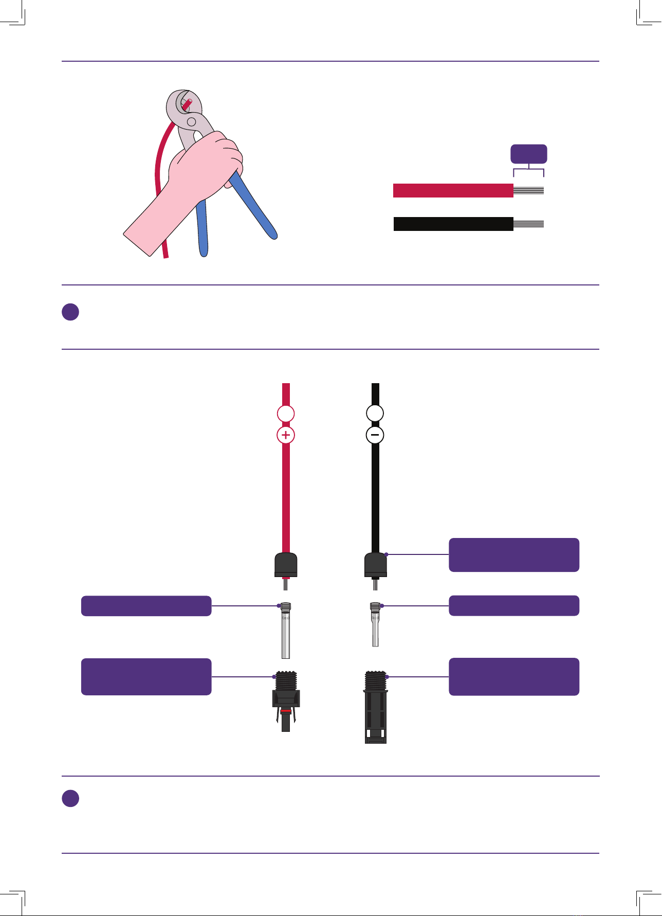
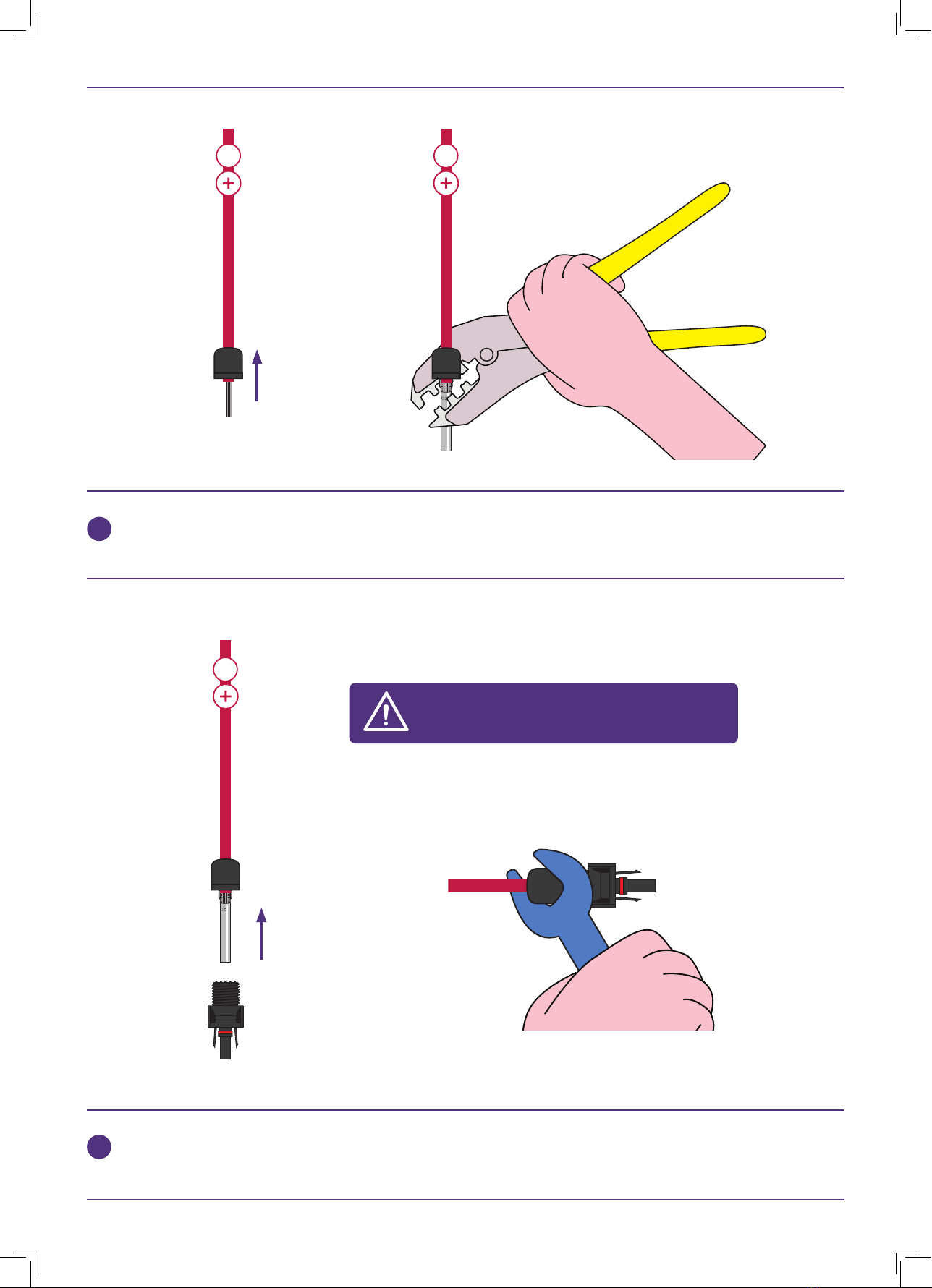
Starting with the red solar cable, place the silicon gland and gland nut onto the cable.
Crimp “Metal Conductor A” onto the cable using the 4mm²crimping die.
Insert the crimped “Metal conductor A” into the “Solar connector housing A” until it clicks, then
tighten the gland nut using a spanner.
5
Pay extra attention to use the correct crimp
conductor, with the correct housing.
A A
A
Lifestyle Kit Manual Hybrid 2022.indd 10Lifestyle Kit Manual Hybrid 2022.indd 10 3/08/22 4:53 PM3/08/22 4:53 PM

11
8
Move onto the black solar cable. Place the silicon gland and gland nut on to the cable.
Crimp “Metal conductor B” onto the cable using the 4mm²crimping die.
Insert the crimped “Metal conductor B” into the “Solar connector housing B” until it clicks, then
tighten the gland nut using a spanner.
7
BB
B
Lifestyle Kit Manual Hybrid 2022.indd 11Lifestyle Kit Manual Hybrid 2022.indd 11 3/08/22 4:53 PM3/08/22 4:53 PM

12
9
10
ON I
OFF O
PV ARRAY
DC ISOLATOR
SISO SWITCH
IP66
ON I
OFF O
PV ARRAY
DC ISOLATOR
SISO SWITCH
IP66
Ensure the PV Array DC isolators are in the off position. Then, connect the PV cable run from
the solar panels. Ensure the other end of the cables stay disconnected from the solar panels.
Repeat the process of crimping MC4 connectors onto a new set of cables (refer to page
9-11), which will connect the PV Array DC isolators to the PV Array fuses.
ON I
OFF O
PV ARRAY
DC ISOLATOR
SISO SWITCH
IP66
ON I
OFF O
PV ARRAY
DC ISOLATOR
SISO SWITCH
IP66
ON I
OFF O
PV ARRAY
DC ISOLATOR
SISO SWITCH
IP66
Ensure the PV Array DC
isolators are in the off position.
Lifestyle Kit Manual Hybrid 2022.indd 12Lifestyle Kit Manual Hybrid 2022.indd 12 3/08/22 4:53 PM3/08/22 4:53 PM

13
11
10X38 ZTPV-25X10X38 ZTPV-25X 10X38 ZTPV-25X
Ensure the solar cable run is NOT connected to the solar panels. Keep
the fuse holders disconnected by keeping them open with the fuses
OUT and the PV Array DC isolators are in the off position.
To disconnect the fuses, pull the front
tabs down to open the fuse holders. Keep the fuse holders open with the
fuses left out of the fuse holders.
10X38 ZTPV-25X 10X38 ZTPV-25X 10X38 ZTPV-25X 10X38 ZTPV-25X
Ensure the fuse holders are disconnected by keeping them open with the fuses OUT. Use wire
strippers to strip the ends of the solar cable, and terminate them in the fuse holders by inserting the
stripped end and tightening the screw clockwise. Make sure the clamp inside the fuse holders are
contacting the metal conductor, and NOT the insulation of the wire.
Lifestyle Kit Manual Hybrid 2022.indd 13Lifestyle Kit Manual Hybrid 2022.indd 13 3/08/22 4:53 PM3/08/22 4:53 PM

14
OFF O
SISO SWITCH
OFF O
SISO SWITCH
The PV Array DC isolators are now wired into the PV Array fuses.
12
Lifestyle Kit Manual Hybrid 2022.indd 14Lifestyle Kit Manual Hybrid 2022.indd 14 3/08/22 4:53 PM3/08/22 4:53 PM

15
000 000 000
0000 000 000
ON I
OFF O
PV ARRAY
DC ISOLATOR
SISO SWITCH
IP66
ON I
OFF O
PV ARRAY
DC ISOLATOR
SISO SWITCH
IP66
10X38 ZTPV-25X10X38 ZTPV-25X 10X38 ZTPV-25X10X38 ZTPV-25X 10X38 ZTPV-25X10X38 ZTPV-25X 10X38 ZTPV-25X10X38 ZTPV-25X
13
Combiner terminal block.
Use the green terminal combiner block to join both the negatives together in one side of the block,
and both positives together in the other side. Then run the section of 16mm ² cable from the M8
bolt terminals to the hybrid inverter.
Lifestyle Kit Manual Hybrid 2022.indd 15Lifestyle Kit Manual Hybrid 2022.indd 15 3/08/22 4:53 PM3/08/22 4:53 PM

16
000 000 000
0000 000 000
ON I
OFF O
PV ARRAY
DC ISOLATOR
SISO SWITCH
IP66
ON I
OFF O
PV ARRAY
DC ISOLATOR
SISO SWITCH
IP66
10X38 ZTPV-25X10X38 ZTPV-25X 10X38 ZTPV-25X10X38 ZTPV-25X 10X38 ZTPV-25X10X38 ZTPV-25X 10X38 ZTPV-25X10X38 ZTPV-25X
14
Keep the fuse holders open, with the
fuses left out of the fuse holders.
When the cables have been terminated in the fuse holders, with the fuses disconnected by
keeping the fuse holders open with the fuses left out and the PV Array DC isolators switched
“OFF”, you can now connect the solar panels to the cable run. The fuses and DC isolators must
be disconnected when connecting or disconnecting the solar panels from the cable run.
For your safety, do not connect or disconnect any solar cables when there is current running
through them.
Lifestyle Kit Manual Hybrid 2022.indd 16Lifestyle Kit Manual Hybrid 2022.indd 16 3/08/22 4:53 PM3/08/22 4:53 PM

17
15 Ensure the 200A MCCB circuit breaker is switched “OFF” (switch in the down position, indicator
showing green). Keep the fuses disconnected by ensuring the fuse holders are open with the fuses left
out and the PV Array DC isolator is switched to the “OFF” position, before wiring.
ON I
OFF O
PV ARRAY
DC ISOLATOR
SISO SWITCH
IP66 Ensure the PV Array DC
isolators are in the off position.
Keep the fuses disconnected by keeping the
fuse holders open with the fuses left out.
10X38 ZTPV-25X 10X38 ZTPV-25X 10X38 ZTPV-25X 10X38 ZTPV-25X
Ensure the 200A breaker is switched off, in
the down position, showing a green indicator.
Lifestyle Kit Manual Hybrid 2022.indd 17Lifestyle Kit Manual Hybrid 2022.indd 17 3/08/22 4:53 PM3/08/22 4:53 PM

18
16 Before proceeding to connect the hybrid inverter to the 200A MCCB circuit breaker, align the 35mm²
x 1m cables between the components to ensure that the M6 ends (smaller holes) are inserted into the
hyrbid inverter and the M8 ends (larger holes) are inserted into the circuit breaker.
Ensure the M6 ends connect to
the hybrid inverter.
Ensure the M8 ends connect to
the 200A MCCB circuit breaker.
Lifestyle Kit Manual Hybrid 2022.indd 18Lifestyle Kit Manual Hybrid 2022.indd 18 3/08/22 4:53 PM3/08/22 4:53 PM

19
17
18
Wire the positive (+) 35mm²x 1m cable from the 200A MCCB circuit breaker to the hybrid inverter.
Wire the negative (-) 35mm²x 1m cable from the hybrid inverter to the 200A MCCB circuit breaker.
000 000 000
0000 000 000
000 000 000
0000 000 000
Lifestyle Kit Manual Hybrid 2022.indd 19Lifestyle Kit Manual Hybrid 2022.indd 19 3/08/22 4:53 PM3/08/22 4:53 PM

20
Please refer to the Battery Mount and Installation Guide for detailed installation instructions.
This manual is included in the ARK lithium battery box.
19
Lifestyle Kit Manual Hybrid 2022.indd 20Lifestyle Kit Manual Hybrid 2022.indd 20 3/08/22 4:53 PM3/08/22 4:53 PM
Other manuals for LIFESTYLE KIT
2
Other GRIDFREE Inverter manuals