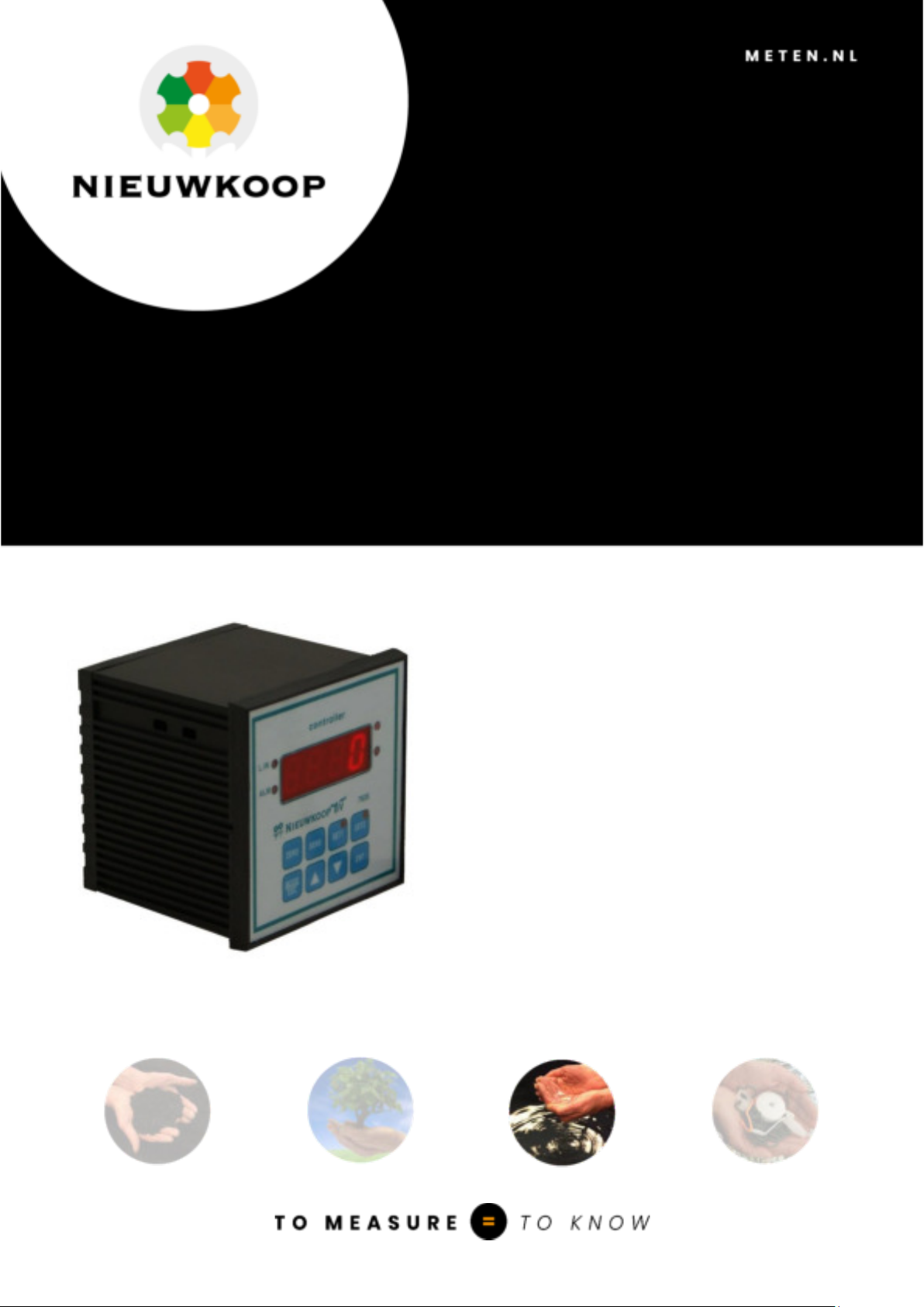
NIEUWKOOP CL3040 User manual

USER MANUAL
CL3040
CHORINE CONTROLLER, PANEL,
2 RELAY

CL3040
CHORINE CONTROLLER, PANEL, 2 RELAY
_____________________________________________________________________________________
1
Scales : 0/2,000/20,00 ppm
Temperature scales : 0.0/50.0 °C
32.0/122.0 °F
Power Supply : 86/264 Vac
Firmware : R 1.0x
Cod. 280067671 Revision C 05/18
INDEX
1 PRODUCT PRESENTATION..................................................................................................................................................................................... 3
1.1 Functional purpose of the unit ............................................................................................................................................................ 3
1.2 Functional principles ..................................................................................................................................................................................... 3
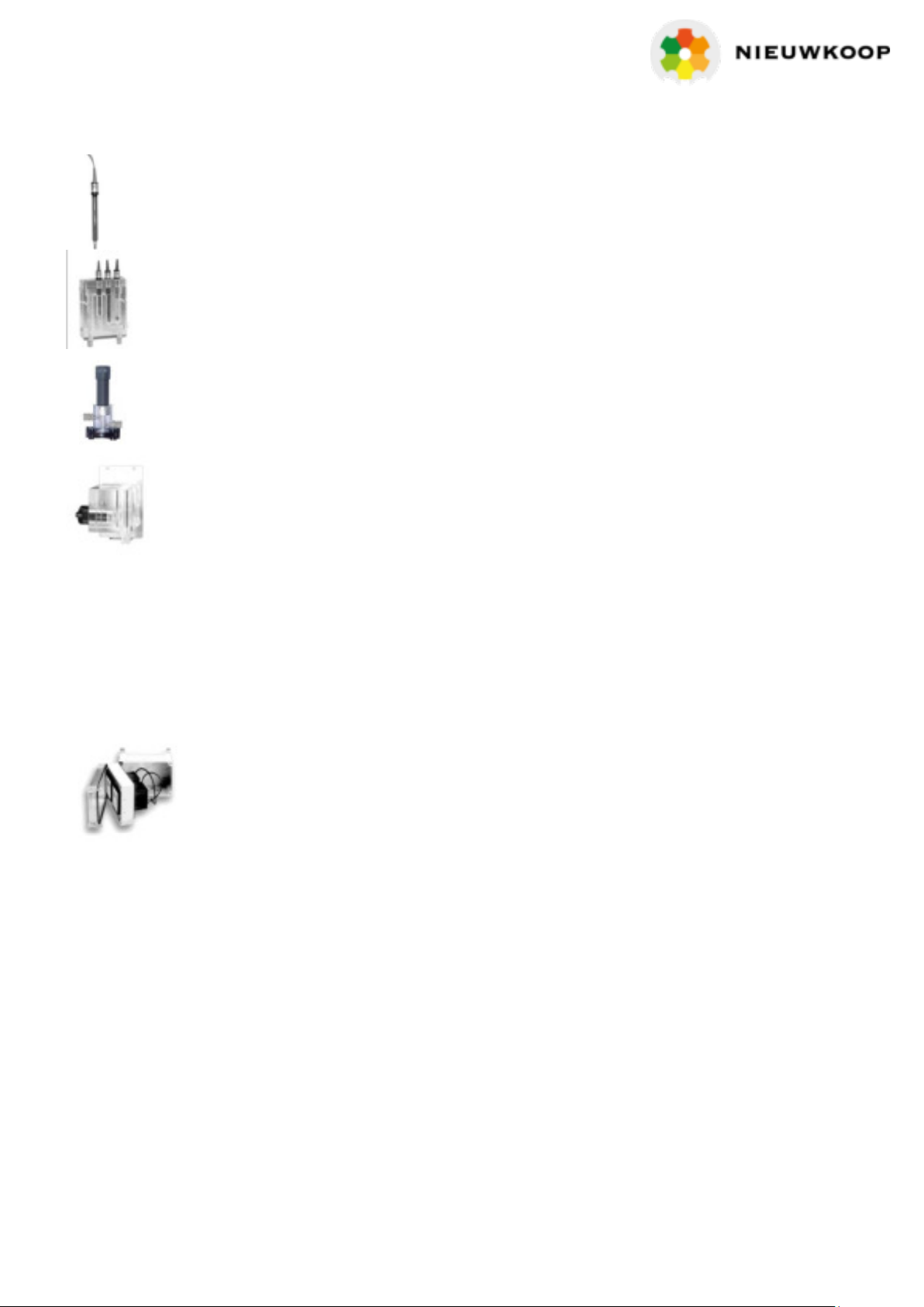
1.3 Sensors and accessories ........................................................................................................................................................................ 4
2 GENERAL WARNINGS AND INFORMATION FOR ALL USERS ............................................................................................... 5
2.1 Warranty ...................................................................................................................................................................................................................... 5
2.2 After sales service ........................................................................................................................................................................................... 5
2.3 CE marking ............................................................................................................................................................................................................... 5
2.4 Safety warnings ................................................................................................................................................................................................ 5
3 INSTRUCTION MANUAL CONTENTS ........................................................................................................................................................... 6
3.1 Manual revision ................................................................................................................................................................................................... 6
3.2 Symbols ....................................................................................................................................................................................................................... 6
3.3 How to read the instruction manual ....................................................................................................................................... 7
3.3.1 Using the instrument on the plant . ................................................................................................................................ 7
3.3.2 Plant maintenance staff ........................................................................................................................................................... 8
3.3.3 Installing the instrument in the plant ........................................................................................................................ 8
4 SPECIFICATIONS ............................................................................................................................................................................................................ 9
4.1 Functional specification ......................................................................................................................................................................... 9
4.2 Technical specifications........................................................................................................................................................................ 11
5 OPERATING PROCEDURES .................................................................................................................................................................................. 15
5.1 Keyboard..................................................................................................................................................................................................................... 15
5.2 Operating instructions ............................................................................................................................................................................ 16
5.2.1 Chlorine or dissolved ozone measuring .............................................................................................................. 16
5.2.2 Temperature measuring ....................................................................................................................................................... 16
5.2.3 Set up parameters ........................................................................................................................................................................ 16
5.2.4 Configuration parameters ................................................................................................................................................. 17
5.2.5 Firmware release ............................................................................................................................................................................ 17
5.3 Instruction for the maintenance staff ................................................................................................................................. 17
5.3.1 Preliminary operations .............................................................................................................................................................. 17
5.3.2 Measuring operations................................................................................................................................................................ 18
5.3.3 Chlorine or dissolved ozone calibration ............................................................................................................ 18

CL3040
CHORINE CONTROLLER, PANEL, 2 RELAY
_____________________________________________________________________________________
2
5.3.4 Set point calibration .................................................................................................................................................................... 19
5.3.5 Temperature calibration ....................................................................................................................................................... 19
5.3.6 Manual temperature compensation ....................................................................................................................20
5.3.7 Set-up ............................................................................................................................................................................................................20
5.3.8 Maintenance of the unit .........................................................................................................................................................22
5.3.9 Maintenance of the sensor ................................................................................................................................................22
5.4 Instructions for the plant engineer ..........................................................................................................................................23
5.4.1 Safety instruction .............................................................................................................................................................................23
5.4.2 Configuration . .....................................................................................................................................................................................23
6 INSTALLATION ....................................................................................................................................................................................................................26
6.1 Packing list..................................................................................................................................................................................................................26
6.2 Unpacking ................................................................................................................................................................................................................26
6.3 Storage and transportation ..............................................................................................................................................................26
6.4 Installation of the unit ................................................................................................................................................................................26
6.5 Installation of the sensor .......................................................................................................................................................................26
6.6 Electrical installation....................................................................................................................................................................................27
6.6.1 Connecting the power ................................................................................................................................................................27
6.6.2 Connecting the sensor .............................................................................................................................................................27
6.6.3 Connecting the temperature sensor .....................................................................................................................28
6.6.4 Connecting the analog output ......................................................................................................................................28
6.6.5 Connecting the pumps, solenoids and alarms .........................................................................................29
6.6.6 Connecting the logic input ..................................................................................................................................................30
7 DISPOSAL ...............................................................................................................................................................................................................................30
Warranty certificate ....................................................................................................................................................................................................33
Repairs ..........................................................................................................................................................................................................................................33
Technical support............................................................................................................................................................................................................34

CL3040
CHORINE CONTROLLER, PANEL, 2 RELAY
_____________________________________________________________________________________
3
1 PRODUCT PRESENTATION
1.1 FUNCTIONAL PURPOSE OF THE UNIT
The basic system for chlorine/dissolved ozone monitoring is made of three important parts:
- the controller described in this instruction manual;
- the sensor;
- the flow cell.
The instrument has the necessary electric circuits and firmware to perform the following functions:
1) as the proper sensor is connected, it displays the chlorine/dissolved ozone concentration values;
2) if a Pt100 or Pt1000 temperature sensor is connected, it will display the temperature values;
3) it performs an automatic or manual temperature compensation;
4) if dosing pumps or solenoids are connected to the specific relays, it will automatically adjust the
conductivity values;
5) if the measure goes outside the low/high limit values, it will give an alarm;
6) it provides an analog output for recording and acquiring the chlorine/dissolved ozone values;
7) to receive an external free voltage contact that activates the alarm or the hold condition.
1.2 FUNCTIONAL PRINCIPLES
The measuring of the free chlorine, chlorine dioxide or dissolved ozone is done by means of two types
of sensors:
- polarographic cell with two electrodes immersed in the suitable electrolyte and with selective
membrane,
- potentiostatic sensor with three electrodes.
A polarization voltage is applied to the anode and cathode of the polarographic cell in order to get an
electrical current into the electrolyte, proportional to the chlorine/d.ozone concentration.
A polarization voltage is applied to the anode and counter electrode of the potentiostatic sensor in
order to get an electrical current into the sample, proportional to the chlorine/d.ozone concentration.
A reference electrode allows the compensation of the ORP and resistance effects.
As a result the measuring is very accurate even at low concentration levels.
The current through the polarographic or potentiostatic cell is effecting a chlorine/d.ozone
consumption, to be renewed by a constant liquid flow.
If the liquid is not regularly renewed the readout will decrease slowly to zero.
This instrument features a manual or automatic temperature compensation, referred to
temperature of 20 °C or 25 °C.
1.3 SENSORS AND ACCESSORIES
The listed articles are the most commonly used ones. They must be ordered separately.
Sensors and accessories for heavier and particular applications are also available.

CL3040
CHORINE CONTROLLER, PANEL, 2 RELAY
_____________________________________________________________________________________
4
SZ 283 potentiostatic sensor for free chlorine and d.ozone, 3 m cable
SZ 7231 flow cell for SZ283 sensor and temperature
SZ 7233 flow cell for SZ283, pH, redox and temperature
SZ 7251 flow cell for SZ283 with autoclean
CL 7901 polarographic sensor for free chlorine, with flow cell and spares
OZ 7901 polarographic sensor for d.ozone, with flow cell and spares
Temperature sensor
SP 514 Pt100 sensor for flow cell
Enclosures
BC 931.2 IP 65 enclosure for one instrument
BC 931.3 IP 65 enclosure for two instruments

CL3040
CHORINE CONTROLLER, PANEL, 2 RELAY
_____________________________________________________________________________________
5
2GENERAL WARNINGS AND INFORMATION FOR ALL USERS
2.1 WARRANTY
This product is guaranteed for all manufacturing defects.
Please take a look at the terms and conditions described on the Warranty Certificate at the end of the
manual.
2.2 AFTER SALES SERVICE
Nieuwkoop B.V./B&C offers to all of its Customers the following services:
- a free of charge Technical Assistance over the phone for problems regarding
installation, calibration and regular maintenance;
- a Repairing Service in our Aalsmeer (Netherlands) headquarter for all types of
damages, calibration or for a scheduled maintenance.
Please take a look at the Technical Support data sheet at the end of the manual for more details.
2.3 CE MARKING
This instrument is manufactured according to the following European Community directives:
• 2011/65/EU "Restriction of the use of certain hazardous substances in electrical
and electronic equipment"
• 2014/35/EU "Low Voltage" LV
• 2014/30/EU "Electromagnetic compatibility" EMC
• EN 61010-1/2011 "Low Voltage" LV
• EN 61326-1/2013 "Electromagnetic compatibility" EMC
–Controlled electromagnetic environment
• EN 55011/2009 "Radio-frequency disturbance characteristics"
–Class A (devices for usage in all establishment other than domestic)
–Group 1 (Industrial equipment that do not exceed 9kHz)
The marking is placed on the packaging and on the S/N label of the instrument.
2.4 SAFETY WARNINGS
It is important to underline the fact that electronic instruments are subject to accidents. For this, it is
important to take all necessary precautions to avoid damages caused by malfunctions.
All types of operations must be performed by authorized and trained staff.
The use of this controller must respect the parameters described in Chapter 4.2 “Technical
specification”, so to avoid potential damages and a reduction of its operating life.

CL3040
CHORINE CONTROLLER, PANEL, 2 RELAY
_____________________________________________________________________________________
6
3 INSTRUCTION MANUAL CONTENTS
This chapter describes the manual and gives suggestions to all users on how to read it and use it.
The manual is written according to the following norms:
- UNI 10893 “Instructions for use”.
- UNI 10653 “Quality of product technical documentation”.
3.1 MANUAL REVISION
This chapter shortly describes the differences between previously released versions of the same
manual, so to help users that are already familiar with the product.
Rev. A First emission.
Rev. B Updates back panel drawing
Rev. C Updated CE marking and alarm limits
3.2 SYMBOLS
Throughout the manual You may find the following symbols, which are both dictated by a Norm or
that are simply conventional:
Symbol Meaning
Attention: pay great attention to what written next to this symbol
------------------- This symbol is used to warn users that if the instructions are
WARNINGS ignored or not correctly followed, damage to the instrument can
-------------------- be caused
Note This symbol is to invite the user to pay particular attention to a
specific section of the manual.
“*” This symbol can be found in those chapters where there have been
changes from the previous releases.

CL3040
CHORINE CONTROLLER, PANEL, 2 RELAY
_____________________________________________________________________________________
7
3.3 HOW TO READ THE INSTRUCTION MANUAL
The manual includes all necessary information to fully comprehend the product, to install it correctly,
to use it and preserving it, and finally to achieve the performances for which You have selected it and
purchased it.
The manual is intended for experienced and prepared personnel, who has knowledge of electronic
instrumentations and industrial plants’ typical operations.
The index guides the reader through the chapters and through the contents that he wishes to know
or exploit.
In particular, the first chapters describe the general characteristics and they allow the reader to
become more familiar with the product by describing its accessories and its use.
The user can then verify if he/she has the necessary know-how to use the controller.
As described in the following chapters, the instrument was designed by keeping in mind three
different kinds of users: generic use (end user), control (maintenance staff), installation (plant
engineer).
Note
Maintenance staff could be more interesting in the chapters regarding:
- users instructions;
- calibration;
- maintenance;
- warranty/repair terms and conditions.
The plant engineer will have to read the chapters and look at the application drawings in order to:
- verify that the technical and functional characteristics are conformed with the plants requirements;
- verify that the environmental and climatic conditions required by the instruments are respected;
- make the correct electronic connections;
- become familiar with the instrument’s firmware;
- configure the instrument according to the application;
- run all of the necessary tests before starting the instrument ;
- calibrate the instrument once the sensor is connected.
3.3.1 Using the instrument on the plant
For the generic use, the end user can operate with a locked keyboard (suggested mode and to be set
by maintenance staff). By this, he can control the data provided without the possibility of changing
the configured set points.

CL3040
CHORINE CONTROLLER, PANEL, 2 RELAY
_____________________________________________________________________________________
8
3.3.2 Plant maintenance staff
Maintenance staff can select the operating values, by setting the desired parameters of the “set up”
menu and after inserting the password. The user’s access to calibration, set point and alarm settings
can also be enable.
The location of this set parameters can be seen in the right column of the Technical Specifications
table (Chapter 4.2) and they are identified by a letter “S” followed by a number.
The operations that need to be done during the start-up and the periodical tests are the following:
- to allow only the visualization of the measures during the normal use;
- to calibrate the sensors by means of ZERO and SENS keys;
- to set the following parameters:
- set point 1 and 2 by means of SET 1 and SET 2 keys
- temperature value in °C or °F
- manual temperature compensation value
- temperature coefficient
- set point 1 and 2 delay
- min. and max. alarm value
- alarm delay
- activate/deactivate logic input;
- to modify password to access set up
3.3.3 Installing the instrument in the plant
The plant engineer, by inserting the access password and by setting and modifying the
“configuration” parameters, will be able to select the necessary functions required by the plant.
The location of this set parameters can be seen in the right column of the Technical Specifications
table (Chapter 4.2) and they are identified by a letter “C” followed by a number.
The configuration that need to be done during the instrument installation are the following:
- cell type;
- measuring scale;
- measuring unit;
- polarization voltage;
- Pt100 or Pt1000 sensor;
- min. and max. (Lo/Hi) function of set-point 1 and 2;
- activated/deactivated (Act/Dea) condition of alarm relay;
- 0/20 mA or 4/20 mA output range;
- hold/alarm function for logic input;
- password changing to access the configuration.

CL3040
CHORINE CONTROLLER, PANEL, 2 RELAY
_____________________________________________________________________________________
9
4 SPECIFICATIONS
4.1 FUNCTIONAL SPECIFICATION
Display
The instrument has a 7 segments and 4 digits LED display. The display shows the measures vales and
the messages to the operator.
In particular, the messages scroll on the display and they are preceded by the corresponding number
of the Technical Specifications tables (Chapter 4.2).
After a 3’ stand-by, the display goes back to the main measuring.
Keyboard
The instrument has 8 keys, which allow to access all of available functions.
The upper keys are for zero and sensitivity calibration and to confirm the set points value. All of this
functions can be then protected by means of password.
The other keys will be described in the following chapters.
Input
The controller can measure the free chlorine, chlorine dioxide or d.ozone concentration and the
temperature.
The measuring unit ppm or mg/l is indicated by the Led positioned to the right of the display.
The concentration is measured by means of a potentiostatic cell or a polarographic cell provided
with a selective membrane.
The temperature value, in °C or °F, can be measured with a Pt100 or Pt1000 temperature sensor; with 2
or 3 wires connection depending to the distance between sensor and controller.
Measuring scales
The instrument features the selection of three scales as shown in the chapter 4.2 “Specifications”.
Temperature compensation
The instrument shows the temperature value and it allows the manual or automatic temperature
compensation.
In case the temperature sensor is absent or it is malfunctioning, the controller turn automatically to
manual compensation and it will show the value of compensation temperature.
The temperature coefficient can be selected according to the specific applications.
Set-points
The instrument has two independent set-points which can be programmed across the whole scale
to activate the correspondent relay contacts (SPST).

CL3040
CHORINE CONTROLLER, PANEL, 2 RELAY
_____________________________________________________________________________________
10
When a relay is activated the corresponding Led, placed to the left side of the display, will light up.
During the phase of activated delay, the LED will flash.
Thanks to the specific front panel keys SET 1 and SET 2, setting the set point value is very simple.
A password can be set in order to avoid that other users may change the settings.
For each relay, it is possible to select:
- min/max function;
- delay.
Alarm
The instrument has an alarm relay, which contact are SPDT type.
The alarm condition can be configured for:
- higher or lower conductivity values compared to the set points;
- logic input signal coming from an external device (if this function is activated);
The alarm status can be seen on the LED marked ALM placed to the left of the display.
During the phase of activated delay, the LED will flash.
The operator can set the activated/deactivated (Act/Dea) status of relay corresponding to the alarm
condition and the delay function.
Analog output
The instrument has an isolated analog output to send the measure value. The output can be
programmed 0/20 mA or 4/20 mA and it is displayed by the main measure.
The galvanic isolated output allows the controller to communicate with a PLC or with a recorder and
it does not need an external power supply.
Logic input
The instrument is equipped with a logic input to connect to external dry contacts.
The logic input function can be activated or deactivated from the set up menu.
The input function can be selected Hold/Alarm, which features are described in table 6.0 of Chapter
4.2 “Technical specifications”, and it is selected in the configuration menu.
Universal power supply
The instrument can operate with an 85/264 Vac power supply.
Power supply option 9/36 Vdc or 24 Vac
By installing this option, the instrument can be used with a 9/36 Vdc or 24 Vac power supply

CL3040
CHORINE CONTROLLER, PANEL, 2 RELAY
_____________________________________________________________________________________
11
Set up
The instrument has the set up menu protected by a specific password.
In the menu, it is possible to deactivate the functions of sensors calibration, set points values and
parameters changing, alarm and logic input parameters changing.
Configuration
The instrument has a configuration menu protected by a specific password.
In the menu, it is possible to select the type of cell, the measuring scale, the measuring unit, the manual
temperature, the temperature coefficient and the temperature sensors, to select the min/max (Lo/Hi)
set point functions, the alarm relay activation type (Act/Dea), the analog output range and the logic
input function.
4.2 TECHNICAL SPECIFICATIONS
The display number is next to the factory values in the following tables.
SETUP parameters are indicated by : “S x.y”
CONFIGURATION parameters are indicated by: “C x.y”
x=table section y=sequence 1..2..3..4..etc.
Underlined words in the tables correspond to scrolling display messages.
1.0 MAIN MEASURING
Factory value
Display
TYPE OF MEASURING
Free chlorine/chlorine dioxide/d.ozone
Cell: potentiostatic (3 wires) (POtE./POLA.)
polarografica (2fwires)
Scales:
Scale Resolution Under Range Over Range
2.000 0.001 0.100 2.100
20.00 0.01 1.00 21.00
200.0 0.1 10.0 210.0
Measuring unit: ppm, mg/l (PPM/MGL)
Potentiostatic cell:
Input current at 20°C: 2000 nA/ppm (mg/l)
Sensitivity: 12.5% / 250% (250/5000 nA/ppm)
Zero: +/- 2000 nA
Polarization: -1000/1000 mV
Polarographic cell:
Input current at 20°C: 160 nA/ppm (mg/l)
Sensitivity: 12.5% / 250% (20/400 nA/ppm)
Zero: +/- 200 nA
Polarization: -1000/1000 mV
POtE
20.00
PPM
100%
0 nA
-200 mV
C1.1
C1.2
C1.3
1.2
1.1
C1.4

CL3040
CHORINE CONTROLLER, PANEL, 2 RELAY
_____________________________________________________________________________________
12
2.0 TEMPERATURE MEASURING
Factory value
Display
TYPE OF MEASURING
Temperature
Input: RTD Pt100/Pt1000
Connection: 3 wires
Measuring unit: °C/°F
Measuring and compensation range: 0.0/50.0°C
(32.0/122.0°F)
Resolution: 0.1°C (0.1°F)
Under range: -2.0°C (28.4°F)
Over range: 52.0°C (125.5°F)
Zero adjustment: +/- 2.0°C (+/- 3.6°F)
Manual temperature: 0/50°C (32/122°F)
Temperature reference: 20 °C
Temperature coefficient: 0.00/4.00%/°C
Pt100
°C
0°C (0°F)
20°C (68°F)
2.0%/°C
C2.1
S2.1
2.1
S2.2
S2.3
3.0 SET POINT
Factory value
Display
SET POINT 1
Action: ON-OFF
Set point (function of the scale): 0.00/20.00
Hysteresis (function of the scale): ± 0.20
Delay: 0.0/100.0 seconds
Function: Lo/Hi (Min/Max)
Relay contacts: SPST 220V 5A resistive
SET POINT 2
Action: ON-OFF
Set point (function of the scale): 0.00/20.00
Hysteresis (function of the scale): ± 0.20
Delay: 0.0/100.0 seconds
Function: Lo/Hi (Min/Max)
Relay contacts: SPST 220V 5A resistive
0
0.2 s
Lo
0
0.2 s
Hi
3.1
S3.1
C3.1
3.2
S3.2
C3.2

CL3040
CHORINE CONTROLLER, PANEL, 2 RELAY
_____________________________________________________________________________________
13
4.0 ALARM
Factory value
Display
Low value (function of the scale): 0.00/20.00
High value (function of the scale): 0.00/20.00
Hysteresis (function of the scale): ± 0.05
Delay: 0.0/100.0 seconds
Relay status (activated/deactivated): Act./dEA.
Relay contacts: SPDT 220V 5A resistive
-1.00
21.00
1.0 s
Act.
S4.1
S4.2
S4.3
C4.1
5.0 ANALOG OUTPUT
Factory value
Display
Range: 0-20/4-20 mA
Under/Over range (0-20): 0.00/20.50mA
Under/Over range (4-20): 3.50/20.50mA
Response time: 2.5 seconds for 98%
Isolation: 250 Vac
R max: 600 ohm
EXTERNAL POWER IS NOT NEEDED
0-20 mA
C5.1
6.0 LOGIC INPUT
Factory value
Display
Logic input: activated/deactivated (On/OFF)
Logic input function: HoLd/ALAr.
HOLD conditions:
Analog output keeps the value (HOLD)
Set points keep the status (HOLD)
Alarm state deactivated (OFF)
ALARM conditions:
Analog output activated (RUN)
Set points deactivated (OFF)
Alarm state activated (ON)
External contacts must be free voltage
OFF
HoLd
S6.1
C6.1

CL3040
CHORINE CONTROLLER, PANEL, 2 RELAY
_____________________________________________________________________________________
14
10.0 SETUP PARAMETERS
Factory value
Display
Password to access the SETUP (0/999)
Calibration and set point adjustment On/OFF
Temperature measuring unit °C/°F
Manual temperature
Temperature coefficient
Delay set1
Delay set2
Alarm LO (low value)
Alarm HI (high value)
Delay alarm
Logic input On/OFF
Modify password to SETUP access
0
On
°C
20.0°C
2.00%/°C
0.2 s
0.2 s
-1.00
21.00
1.0 s
OFF
0
10.1
S1.1
S2.1
S2.2
S2.3
S3.1
S3.2
S4.1
S4.2
S4.3
S6.1
S10.1
11.0 CONFIGURATION PARAMETERS
Factory value
Display
Password to access CONFIGURATION (0/999)
Cell type POte./POLA.
Scale 2.000/20.00/200.0
Measuring unit PPM / MGL
Polarization -1000/1000mV
Temperature sensor Pt100/Pt1000
Set point 1 function Lo/Hi
Set point 2 function Lo/Hi
Alarm relay status Act./dEA.
Analog output range 0-20/4-20 mA
Logic input function HoLd/ALAr.
Modify password to CONFIGURATION access
0
POtE
20.00
PPM
-200mV
Pt100
Lo
Hi
Act.
0-20 mA
HoLd
0
11.1
C1.1
C1.2
C1.3
C1.4
C2.1
C3.1
C3.2
C4.1
C5.1
C6.1
C11.1
GENERAL SPECIFICATIONS
Display: LED 7 segments and 4 digits
Led indicators: -set1 and set2 relay status
-alarm status
-logic input contact status
-measuring unit ppm
-measuring unit mg/l
Operating temperature: 0/50°C
Humidity: 95% without condensation
Power supply: 85/264 Vac 50/60 Hz
Isolation: 4000 Vdc (2350 Vac) between primary and secondary
(IEC 348)
Power consumption: 6 VA max.
Terminal blocks: extractable
Weight: 450 g
Dimensions: 9 6 x 96 x 104 mm including frame.
Dimensions (internal to switch board): 90 x 90 x 95 mm

CL3040
CHORINE CONTROLLER, PANEL, 2 RELAY
_____________________________________________________________________________________
15
5 OPERATING PROCEDURES
1. Values and messages display 4. Selected measuring unit (ppm)
2. Logic input contact visualization 5. Selected measuring unit (mg/l)
3. Active alarm visualization 6. Set point relay activated
7. Keyboard
Fig. 1
5.1 KEYBOARD
“Mode - Esc”
-Visualizes instrument functions
-Exit without changing the values
“Up”
-Increase the values
-Changes the options
“Down”
-Decrease the values
-Changes the options
“Enter”
-Enter the new values
-Starts the visualized function
“Zero”
Starts zero calibration
“Sens”
Starts sensitivity calibration
“Set1”
Starts set point 1 calibration
“Set2”
Starts set point 2 calibration

CL3040
CHORINE CONTROLLER, PANEL, 2 RELAY
_____________________________________________________________________________________
16
5.2 OPERATING INSTRUCTIONS
5.2.1 Chlorine or dissolved ozone measuring
The display shows the main measure values as selected in the configuration menu.
The front panel LED is lit according to the selected measure.
Display 1.0
If the measuring value is under range/over range, the following messages will appear:
and
From this display 1.0 it is possible to start the sensors calibration procedure, the set points
setting (if those functions have been enabled in the set up menu).
From this display 1.0 it is possible to start the sensors calibration procedure, the set points setting (if those
functions have been enabled in the set up menu).
by pressing the key, the LED 4 or 5 on the front panel are switched off and the analog output range and the
expected current on the load are displayed.
or
5.2.2 Temperature measuring
By pressing the key from the 1.0 display, the unit will show the message
(o ), if the RTD is not connected the message and the temperature value (actual value or
the manual value selected in the display S2.2).
Display 2.0
From this display it is possible the access to the calibration procedure of the temperature probe if this
function is enabled by the operator.
5.2.3 Set up parameters
The set up parameter changing can be enabled/disabled by the operator.
By pressing two times the key from the 1.0 display, the unit will show the message
and it is possible to access to the menu reserved to maintenance staff (set-up)

CL3040
CHORINE CONTROLLER, PANEL, 2 RELAY
_____________________________________________________________________________________
17
Display 10.0
5.2.4 Configuration parameters
By pressing three times the key from the 1.0 display, the unit will show the message
and it is possible to access to the menu reserved to the plant engineer
(configuration)
Display 11.0
5.2.5 Firmware release
By pressing four times the key from the 1.0 display, the unit will show the message
(it shows the unit p/n and the release of the firmware installed in the unit).
Display 12.0
By pressing the key, the unit turn back to the main display.
5.3 INSTRUCTION FOR THE MAINTENANCE STAFF
5.3.1 Preliminary operations
All the functioning operations must be done with sensor connected to the unit.
Verify if the configuration, the set point and the alarm parameter are suitable for the current
application.
Follow the procedures described in the chapter 5.3.7 to verify the parameters without modifying the
values.
The display, LED and keys in the front panel allow the operator to perform the preliminary check.
A lit display indicates that the unit s powered and the power circuits work correctly.

CL3040
CHORINE CONTROLLER, PANEL, 2 RELAY
_____________________________________________________________________________________
18
5.3.2 Measuring operations
In order to correctly operate the system, remember to verify the following:
- sensors are installed and in contact with the liquid;
- analog output if necessary;
- eventual actuation of the relays 1 and 2;
- alarm relay if necessary;
- logic input if necessary;
- power supply and ground;
Power the unit and read the chlorine/d.ozone concentration value and the status of the set points.
If sensors are connected correctly as described in chapter 6 "Installation", the system will operate
properly and it will only need the calibration and the set point/ alarm values setting.
5.3.3 Chlorine or dissolved ozone calibration
Install the cell into the flow cell and connect it to the instrument.
By keeping the cell in air or dipped into a sample without chlorine/d.ozone, the display will show zero.
If the readout is different than zero it is possible to perform the following zero calibration
By pressing the key, the unit will show the message
followed by the actual chlorine or dissolved ozone value, or if the calibration
function has been disabled into the set up menu (display S1.1).
press to confirm and to end the calibration.
ormessages will appear.
The message of error must be confirmed if the calibration has not been ended successfully.
The chemical calibration is performed by adjusting the sensitivity of the instrument in order to read
on the display the same value of the sample concentration.
The user must know the concentration of the sample or he must measure by means of a field or
laboratory equipment. (example through DPD).
Follow the next steps:
By pressing the key, the unit will show the message
followed by the actual concentration value, or if the calibration function has
been disabled into the set up menu (display S1.1).
orpress the keys to change the value according to sample concentration,
press to confirm and to end the calibration

CL3040
CHORINE CONTROLLER, PANEL, 2 RELAY
_____________________________________________________________________________________
19
ormessages will appear.
The message of error must be confirmed if the calibration has not been performed.
If the operator needs to turn to the factory calibration of the zero or the sensitivity
press the three keys together instead of using the keys
The following messages will appear or
The error messages during the calibration inform the operator about the bad condition of the cell.
The zero > 200 nA (polarographic) or zero> 2000 nA (potentiostatic) will show the message ,
to indicate the pollution of the sensor, the needing of the sensor maintenance or problems on the
cable.
The sensitivity < 12.5% or > 250% will show the message , to indicate the needing of sensor
maintenance.
5.3.4 Set point calibration
or By pressing the key, the unit will show the message
()or(depending on the configuration done in display C3.1 o C3.2) followed by the
actual value,
or press the keys to change the value
will appear if the calibration has been disabled in the set up display S1.1).
press to confirm and to end the calibration.
press the key to exit from the procedure without changing the data (this key allows to exit
from all the procedure without changing the previous data/setting).
5.3.5 Temperature calibration
By pressing the key from the main display, the unit will access the temperature readout.
By pressing the key, the unit will show the message
followed by the actual value, or if the calibration function has been disabled into
the set up menu (display S1.1).
or press the key to change the value
press to confirm and to end the calibration
message or will appear.
Table of contents
Other NIEUWKOOP Controllers manuals
Popular Controllers manuals by other brands

Musica
Musica MUSICAVC-70ZS installation instructions

Heatit Controls
Heatit Controls Z-PUSHaZ-PUSH 45 126 92 Installer manual

Valcom
Valcom V-2000 manual

Phoenix Contact
Phoenix Contact ILC 130 ETH user manual

Magnetek
Magnetek SBN Series instruction manual

gefran
gefran SIEIDrive ADV100 Functions description and parameters list