manuals.online logo
Brands
  1. Home
  2. •
  3. Brands
  4. •
  5. KELCO
  6. •
  7. Controllers
  8. •
  9. KELCO PG20 Series Instruction Manual

KELCO PG20 Series Instruction Manual

WARNING
Please read this installation sheet fully and
carefully. The PG20 Pressure Guard is a mains
voltage device. Death or serious injury may
result if this product is not correctly installed
and used.
INTRODUCTION
The PG20 Pressure Guard is a microprocessor controlled
solid-state pressure switch. It is designed for guarding
pipework and equipment against over or under pressure.
The PG20 features two adjustable trip points that can be
independently set to stop a pump if pressure exceeds
settable levels. The low level trip point feature has an
automatic 10-second time delay buffer built in to allow
normal pressure fluctuations to be ignored. System
pressure can drop to below the low level trip point setting
for up to 10 seconds without triggering the switch and
shutting down any equipment in the control circuit. The
PG20 also has a fine tune zeroing adjustment that allows
the switch to be calibrated accurately to any required
pressure within its range. The fine tune adjustment dial
can also be used to offset the entire operating range of
the switch and to select pressure set points that may lie in
between the main dial graduations of the switch.

WARNING
The PG20 Pressure Guard is water resistant
to IP67. This rating only applies if the clear
control lid is in place and its two fixing screws
fully tightened. The PG20 is not water resistant
unless the clear lid is in place and fully secured.
Always replace the clear lid and fully tighten
its two screws after making changes to the
settings. The PG20 may present a shock hazard
and death or serious injury may result if water
enters the PG20’s electrical housing. There are
no user serviceable parts in this device. Under
no circumstances should the main housing be
opened. Warranty on this product is automatically
void if the sealed body screws are opened.
IMPORTANT
This installation and usage information sheet must be
read with reference to the specific switch model being
installed. The supply voltage, power switching capacity
and the pressure rating of the switches may vary from
model to model and it is very important to understand the
limitations of a specific model before installing it.
MODELS
PG20 - 240 - S - 5 - NO
CONTACTS
NO = NORMALLY OPEN
NC = NORMALLY CLOSED
CABLE CORES
4 = 4 CORE 10Amp CABLE
5 = 5 CORE 16Amp CABLE
SUPPLY VOLTAGE
240 = 220 to 240VAC
24 = 24VAC or DC
PRESSURE RANGE
20 = 0 to 20 Bars
CABLE
NO LETTER - 10Amp PLUG & PLAY
HD = HEAVY DUTY 15Amp CABLES 2 X 2M LONG
S = SINGLE CABLE 2M LONG WITH 4 or 5 CORES
OPERATING ENVIRONMENT
Ambient Temperature Range 1ºC to 50ºC
Liquid Temperature Range 1ºC to 60ºC, See note below
Ingress Protection Rating IP67
Supply PG20-240
(all 240VAC Models)
220 to 250VAC 50Hz
Supply PG20-24-S-5
(24VAC/DC Model)
12 to 28 Volts AC or DC, 100mA
OPERATING RANGE
High Pressure Trip Point Adjustable from 5 to 19 Bars in
15 steps
Can also be set to zero if high cut
out is not required
Low Pressure Trip Point Adjustable from 1 to 15 Bars in
15 steps
Can also be set to zero if low cut
out is not required
Fine Tune Adjustment Range is plus to minus 1 Bar in
16 steps
Start Timer Adjustment
Range
Adjustable from zero to
180 seconds in 16 steps
Maximum Switched Load
PG20-240-S-5
240VAC 50Hz 6Amps
For control circuit applications only
Maximum Switched Load
PG20-24-S-5
240VAC 50Hz 6Amps
For control circuit applications only
Maximum Switched Load
PG20-240-S-4
240VAC 50Hz 10Amps
(for motor loads to 3HP only)
Maximum Switched Load
PG20-240-HD
240VAC 50Hz 15Amps
(for motor loads to 5HP only)
Operating Pressure Range 0 to 20 Bars (0 to 300psi),
See note below
Burst Pressure 45 Bars (650 psi)
WARNING SAFETY NOTE: In the interests of safety
the PG20 Pressure Guard must NOT be used in hot
water applications (>60ºC). The PG20 Pressure Guard
is designed to operate at pressures up to 20 Bars (300
psi) and must not be used in applications where either
the static or dynamic pressure exceeds this rating.
INSTALLING AND USING
THE KELCO PG20 PRESSURE GUARD
INSTALLATION
The PG20 is suitable for use in all cold-water based
applications such as potable water, seawater, bore
water, chlorinated pool water, brackish water or effluent.
A suitable location should be selected for the switch in
the delivery pipework of the pump. The switch should be
installed in a location that is away from both vibration and
heat, preferably out of direct exposure to the weather and
above any flood level. Drill and tap a 1/4” BSP thread in
the pipework at the required location and fit the PG20
Pressure Guard using a 1/4” brass or stainless nipple (not
supplied). The PG20 can be mounted in any orientation
required in either vertical or horizontal pipework.
Apply a suitable thread sealant tape or thread paste
and screw the PG20 and its interposing nipple into the
pipework using the spanner flats provided. When properly
installed the controller should be square to the axis of the
pipe with the controls in an accessible position.
ELECTRICAL
IMPORTANT
The PG20 Pressure Guard is available in a number of
configurations. Options include various supply voltages
and output contacts that may be normally open or
normally closed. The PG20 is also available with a built
in high capacity output drive system for the direct control
of large single phase pump motors. Check the model
number before installing this device to ensure you are
installing the correct model for the specific application.
The PG20 Pressure Guard requires a stable supply
voltage in order to operate correctly. Pay particular
attention to cable sizes and ensure cables are adequate
for the specific load. This is particularly important where
long cable runs are to be used in the installation. If the
voltage drop associated with the starting of the pump
motor is excessive the PG20 will automatically reset and
this may cause the pump to jog. Jogging can snap the
main spindle of a pump very easily, so please take all
precautions to ensure the voltage supply to the PG20 is
stable and that the current carrying capacity of the cable
is adequate for the job. For mains voltage applications we
recommend that the supply to the PG20 be isolated by a
10Amp RCD that has a maximum trip current of 30mA.
WARNING
When installing the PG20 the socket outlet
connection (GPO) for the input power must be
accessible and must be positioned in a dry and
protected location out of the weather and above
any flood or water level. Where the PG20 is to be
used to control pump motors up to 2.4kW 3HP
the supply to the PG20 must be protected by a
10 Amp fuse or by a 10 Amp circuit breaker.
FIXED INSTALLATION
WARNING
Mains voltage fixed installations must only ever
be carried out by a licensed electrician and must
conform to local wiring rules.
BROWNOUT OR BLACKOUT
If a blackout or brownout occurs while the PG20 is
operating, the pressure switch will not retain any memory
of its previous state. It will simply shut down the system.
When power resumes the PG20 will reboot, restart
the system and run the preset start-up time from the
beginning. A manual reboot can be done at any time by
simply pressing the reset button on the top deck of the
switch.
ADJUSTING SETTINGS
There are 4 rotary switches located under the clear cover
on the top deck of the PG20. These 4 dials are for adjusting
the settings that control the PG20’s actions. To access
the 4 dials undo the 2 screws that hold the clear cover in
place. Note that the clear cover must always be replaced
and tightened after making changes to the settings. Any
changes to the settings will not take effect until the reset
button is pressed or the supply is reset.

WARNING
Without the cover in place the PG20 is not water
resistant and presents a potential shock hazard.
Take great care not to splash water onto the
PG20 when the control cover is removed and
always replace the cover immediately and fully
tighten its securing screws after any changes to
the settings are made.
After you make any change to the settings on the 4
control dials you must always press the reset button
for the changes to take effect.
1
2
3
4
5
6
7
8
No. DESCRIPTION FUNCTION
1 MASTER RESET BUTTON With power on, press this button to start the system at any time. Always
press it after making any changes to the settings on the 4 dials. Any changes
you have made will not take effect until you press the reset button. This
button can be pressed at any time. The start timer is reset to zero when the
reset button is pressed.
2 FINE TUNE SETTING This dial allows the entire pressure range of the switch to be shifted up or
down in a series of fine steps. In effect, it allows the PG20 to be zeroed
in against any pressure within the overall range of 0 to 20 Bars. Using the
fine tune dial it is possible to set the PG20 to trip at virtually any point
above or below the settings on the main pressure setting dials. Turning this
dial clockwise raises the high and low set points. Turning it anticlockwise
lowers the set points.
3 START-UP TIMER Each time power is turned on or the reset button is pressed the PG20
switches its output on and holds it on for the time set on this dial. The range
of adjustment is zero to 180 seconds in 16 steps. The start-up timer gives
the system time to pressurise and for the pressure to rise to a level higher
than the low level trip point set on the PG20. If the pressure fails to rise to
above the point that the low pressure trip is set to, the PG20 runs its fixed
10 second dip timer and then shuts down the system and rapidly flashes its
blue light (6) to indicate there is a low pressure problem. Pressing the reset
button causes the PG20 to reset the system, pump the pump and again
reattempt to raise the system’s pressure.
WARNING Use the start timer carefully and never set the start time to
longer than the minimum required to prime the system. The system pressure
is not monitored while the start timer is running and can potentially rise to
excessive levels during an excessive start time.
4 LOW PRESSURE TRIP POINT This dial sets the low-pressure trip point. It is adjustable from 0 to 15 Bars in
steps of one Bar. If the system pressure falls to below this setting the PG20
runs its internal 10 second dip timer and then rechecks the pressure. If after
the 10 second delay period the pressure is still below the pressure set on
this dial, the PG20 shuts down the system and rapidly flashes its blue alarm
light (6). The system can only be started by resetting the power or pressing
the reset button. The low pressure trip point can be set to zero if no low
pressure cut out is required. With this dial set to zero, the PG20 becomes a
dedicated high pressure cut out switch with no low pressure limit.
5 HIGH PRESSURE TRIP POINT This dial sets the high pressure trip point. It is adjustable from 0 to 19 Bars
in one Bar steps. If the system pressure rises to above the pressure set
on this dial the PG20 shuts down the system and rapidly flashes its red
alarm light (8). Once tripped the system will not restart unless the power
is reset or the reset button is pressed. The high pressure trip point can be
set to zero if no high pressure cut out is required. With this dial set to zero
the PG20 becomes a dedicated low pressure cut out switch with no high
pressure limit.
6 BLUE
START TIMER LED &
LOW PRESSURE ALARM
This light shows steady blue whenever the start timer is running. It also
flashes rapidly blue if the system has shut down on low pressure. It indicates
a low pressure problem.
7 GREEN
NORMAL RUN LED
This light will show a steady green whenever the system is operating within
its normal pressure range. It means all is OK. This light will also flash rapidly
green for up to 10 seconds if the pressure dips to below the low pressure
trip point. It does this to indicate the pressure is low and the system will be
shut down if the pressure fails to rise to within its correct limits within 10
seconds.
8 RED
HIGH PRESSURE
ALARM LED
This light flashes rapidly red if the PG20 as tripped out on high pressure.
If the pump has exceeded the pressure set on the high pressure trip point
dial (5) this light will flash rapidly red. It means the PG20’s alarm feature
has been activated and the system has been shut down because of a high
pressure fault.
GETTING THE SETTINGS WRONG
If the pressure setting dials are not correctly set the PG20
Pressure Guard will not allow the system to start. The
lights (6), (7) and (8) will flash rapidly and alternately red
green and blue to indicate to you that there is a problem.
Check the dial settings and make sure the high pressure
trip point is set to a higher pressure than the low pressure
trip point. Once you have corrected the switch settings,
press the master reset button for the changes to take
effect. The system should then start normally.
LIMITATIONS
The PG20 Pressure Guard requires a stable voltage
supply in order to operate properly. Where large pumps
are connected to a PG20 care should be taken to ensure
cable sizes are adequate. Never use the PG20 with
long or coiled extension leads or on generator sets. The
electronics built into the PG20 are protected against
surges and brownouts and these protection systems can
be triggered by voltage drop, severe voltage spikes or by
an erratic electrical supply.
The PG20 should only be used in ambient temperature
water applications. It is neither designed for, nor is it
intended to be used with liquids other than water. The
PG20 must never be used in hot water applications
(greater that 60ºC) and must also be protected from
freezing in cold water applications.
The PG20 is designed to withstand water pressures up
to 20 Bars (300 psi) and must not be used in applications
where either the static or dynamic pressure exceeds this
rating.
WARNING
If the PG20 Pressure Guard is used in a manner
not specified by the manufacturer the protection
provided by the device may be impaired or
negated. In addition, all warranties stated or
implied will be rendered invalid.
MADE IN AUSTRALIA BY
KELCO Engineering Pty Ltd
ABN 20 002 834 844
Head Office and Factory: 9/9 Powells Road BROOKVALE 2100 AUSTRALIA
Postal Address: PO Box 496 BROOKVALE NSW 2100
Phone: +61 2 9905 6425 Fax: +61 2 9905 6420
Email: [email protected] Web: www.kelco.com.au
PLEASE NOTE: The Kelco PG20 Pressure Guard is the subject of Australian and International patent and trademark applications.
Kelco Engineering Pty Ltd reserves the right to change the specification of this product without notice. Kelco Engineering Pty Ltd accepts no liability
for personal injury or economic loss as a consequence of the use of this product. All rights reserved copyright Kelco Engineering Pty Ltd © 2010

This manual suits for next models

1

Other KELCO Controllers manuals

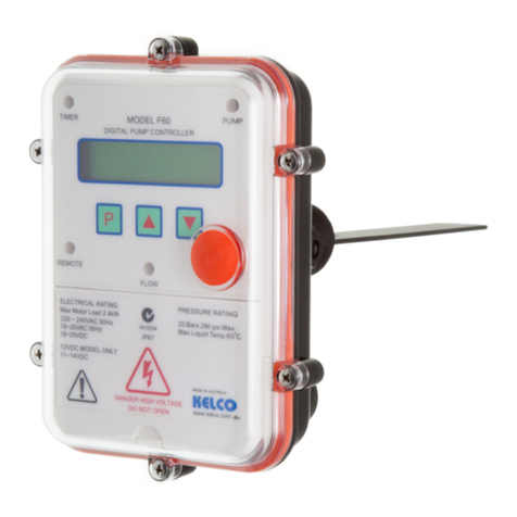
KELCO F60 Installation manual

KELCO

KELCO F60 Installation manual

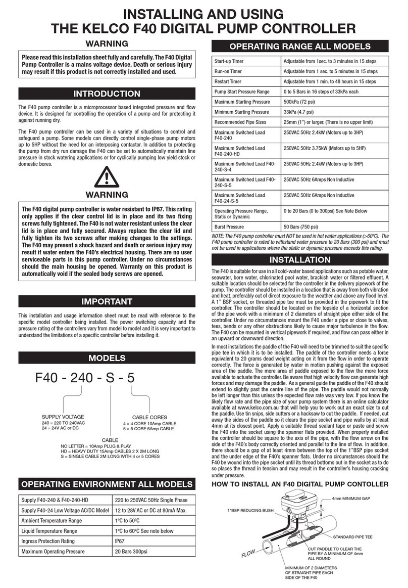
KELCO F40 Series Guide

KELCO

KELCO F40 Series Guide

KELCO F60 MK3 Assembly instructions

KELCO

KELCO F60 MK3 Assembly instructions

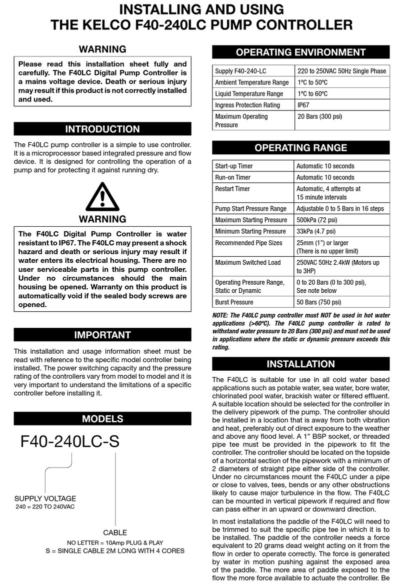
KELCO F40-240LC Guide

KELCO

KELCO F40-240LC Guide

KELCO F60 Mk2 Assembly instructions

KELCO

KELCO F60 Mk2 Assembly instructions

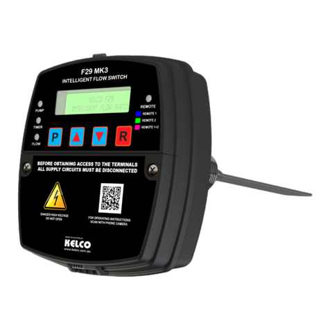
KELCO F29 MK3 Assembly instructions

KELCO

KELCO F29 MK3 Assembly instructions

KELCO F30 User manual

KELCO

KELCO F30 User manual

KELCO F30 User manual

KELCO

KELCO F30 User manual

KELCO F60 User manual

KELCO

KELCO F60 User manual

Popular Controllers manuals by other brands

Honeywell CENTRALINE EAGLE user guide

Honeywell

Honeywell CENTRALINE EAGLE user guide

Emerson DL8000 instruction manual

Emerson

Emerson DL8000 instruction manual

YASKAWA MP2000 Series user manual

YASKAWA

YASKAWA MP2000 Series user manual

Leviton RTD01-10 installation instructions

Leviton

Leviton RTD01-10 installation instructions

Newport XPS Series Technical note

Newport

Newport XPS Series Technical note

EMR LX10.2 instruction manual

EMR

EMR LX10.2 instruction manual

Niko 05-711 manual

Niko

Niko 05-711 manual

nVent RAYCHEM HWAT-ECO V5 Installation, operation and maintenance manual

nVent RAYCHEM

nVent RAYCHEM HWAT-ECO V5 Installation, operation and maintenance manual

Honeywell AUTOMATIC CONTROL Engineering manual

Honeywell

Honeywell AUTOMATIC CONTROL Engineering manual

Kohler K-1663 installation guide

Kohler

Kohler K-1663 installation guide

Omron SYSMAC One NSJ Series Operation manual

Omron

Omron SYSMAC One NSJ Series Operation manual

Siemens SIRIUS 3RT203 S Series Original operating instructions

Siemens

Siemens SIRIUS 3RT203 S Series Original operating instructions

KaMo MDF Series manual

KaMo

KaMo MDF Series manual

Sav SAV 876.17 operating instructions

Sav

Sav SAV 876.17 operating instructions

MWP W4B-120C Installation and operation manual

MWP

MWP W4B-120C Installation and operation manual

GE RSTi-EP user manual

GE

GE RSTi-EP user manual

Bettis TEC2 quick start guide

Bettis

Bettis TEC2 quick start guide

S&C 6800 Series instruction sheet

S&C

S&C 6800 Series instruction sheet

manuals.online logo
manuals.online logoBrands
  • About & Mission
  • Contact us
  • Privacy Policy
  • Terms and Conditions

Copyright 2025 Manuals.Online. All Rights Reserved.