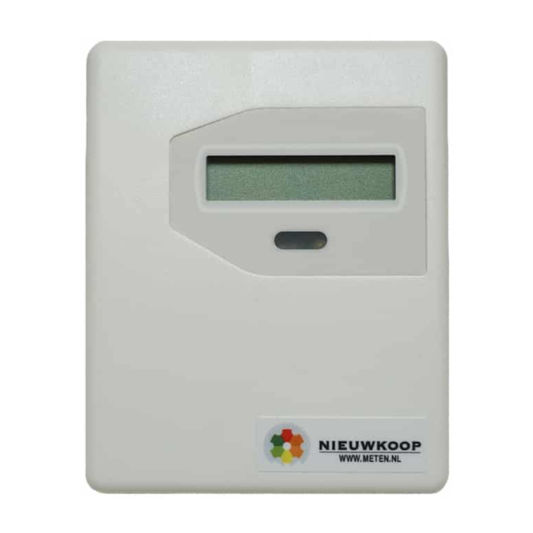
NIEUWKOOP EC3000 User manual

USER MANUAL
EC3000
EC-TRANSMITTER
Isolated output 4-20mA

EC3000
EC-TRANSMITTER
_____________________________________________________________________________________________
2
Conductivity Scale : 0/199.9 µS –0/1999 µS
0/19.99 mS
Temperature Scale : -10.0/+120.0 ˚C
Power Supply : 10/30 Vdc
Cod. 28003364
Rev. C –01/19
Valid from S/N 39252
INDEX
1GENERAL WARNINGS AND INFORMATION FOR ALL USERS.........................................................................................................................3
1.1 WARRANTY.........................................................................................................................................................................................................................................3
1.2 AFTER SALES SERVICE ............................................................................................................................................................................................................3
1.3 CE MARKING....................................................................................................................................................................................................................................3
1.4 SAFETY WARNINGS..................................................................................................................................................................................................................3
2GENERAL........................................................................................................................................................................................................................................................ 4
3FUNCTIONAL DESCRIPTION.......................................................................................................................................................................................................4
4PHYSICAL DESCRIPTION................................................................................................................................................................................................................ 4
5SPECIFICATIONS................................................................................................................................................................................................................................... 5
6 PHYSICAL INSTALLATION..............................................................................................................................................................................................................6
7 ELECTRICAL INSTALLATION..........................................................................................................................................................................................................7
7.1 CONNECTING THE POWER................................................................................................................................................................................................7
7.2 CONNECTING THE 2-ELECTRODES CELL...........................................................................................................................................................7
7.3 CONNECTING THE 4-ELECTRODES CELL..........................................................................................................................................................7
7.4 CONNECTING THE TEMPERATURE SENSOR...................................................................................................................................................8
8 SYSTEM CHECKING............................................................................................................................................................................................................................8
9 OPERATING THE SYSTEM............................................................................................................................................................................................................... 9
9.1 PRE-OPERATION CHECK....................................................................................................................................................................................................9
9.2 ELECTRICAL CALIBRATION.............................................................................................................................................................................................10
10 NORMAL OPERATION.........................................................................................................................................................................................................................11
10.1 MANUAL TEMPERATURE COMPENSATION ........................................................................................................................................................11
10.2 CELL CONSTANT ADAPTATION...................................................................................................................................................................................11
10.3 CHEMICAL CALIBRATION OF THE CONDUCTIVITY .................................................................................................................................11
11 PREVENTIVE MAINTENANCE......................................................................................................................................................................................................13
11.1 TRANSMITTER..................................................................................................................................................................................................................................13
11.2 SENSOR...............................................................................................................................................................................................................................................13
12 TROUBLESHOOTING GUIDE.......................................................................................................................................................................................................14

EC3000
EC-TRANSMITTER
_____________________________________________________________________________________________
3
1 GENERAL WARNINGS AND INFORMATION FOR ALL USERS
1.1 WARRANTY
This product is guaranteed for all manufacturing defects.
Please take a look at the terms and conditions described on the Warranty certificate at the end of the
manual.
1.2 AFTER SALES SERVICE
Nieuwkoop B.V./B&C offers to all of its Customers the following services:
- a free of charge technical assistance over the phone for problems regarding installation,
calibration and regular maintenance;
- a repairing service in our Aalsmeer (Netherlands) headquarter for all types of damages,
calibration or for a scheduled maintenance.
Please take a look at the technical support data sheet at the end of the manual for more details.
1.3 CE MARKING
This instrument is manufactured according to the following European Community directives:
• 2011/65/EU "Restriction of the use of certain hazardous substances in electrical and electronic
equipment"
• 2014/30/EU "Electromagnetic compatibility" EMC
• EN 61326-2-3/2013 "Electromagnetic compatibility" EMC
–Controlled electromagnetic environment
• EN 55011/2009 "Radio-frequency disturbance characteristics"
–Class A (devices for usage in all establishment other than domestic)
–Group 1 (Industrial equipment that do not exceed 9kHz)
The marking is placed on the packaging and on the S/N label of the instrument.
1.4 SAFETY WARNINGS
It is important to underline the fact that electronic instruments are subject to accidents. For this, it is
important to take all necessary precautions to avoid damages caused by malfunctions.
All types of operations must be performed by authorized and trained staff.
The use of this controller must respect the parameters described in chapter “Technical specification”, so
to avoid potential damages and a reduction of its operating life.

EC3000
EC-TRANSMITTER
_____________________________________________________________________________________________
4
2 GENERAL
This manual applies to the C 3630 digital 2-wire transmitter DIN RAIL housing.
It explains the purpose of the equipment, describes the components of the system and the procedures
for installing, operating and calibrating the equipment. Some maintenance suggestions are also
provided.
3 FUNCTIONAL DESCRIPTION
This transmitter, when connected to the E.C. cell provides a digital readout of the conductivity of aqueous
solutions.
The transmitter will perform manual or automatic temperature compensation to correct conductivity
readings for temperature related variations.
Temperature information is displayed by pushing button "2" marked "TEMP". Measuring scales, operating
frequency and decimal point are selectable.
The transmitter provides an isolated 4/20 mA output, proportional to the conductivity value which is
suitable for data acquisition systems, recorders, controllers or other input devices that require a 4/20 mA
input.
The front panel contains trimmer pots for Zero and Cell constant adjustment. Zero is adjusted by
trimmer "3" marked "ZERO" and Cell constant is adjusted by trimmer "4" marked "SENS".
4 PHYSICAL DESCRIPTION
The transmitter enclosure is designed for DIN Rail mounting.
It consists of a plastic case with front panel which is coated by a polycarbonate membrane (Fig. 1), to
ensure maximum anticorrosion characteristics.
For field applications mounting in a splash proof or weather resistant box is suggested. Figure 3
describes the physical details and dimensional characteristics.
Connections to power supply, loads, recorder, RTD, electrodes and probe are installed on to the terminal
block connector.

EC3000
EC-TRANSMITTER
_____________________________________________________________________________________________
5
5 SPECIFICATIONS
Display
LCD
Input
2-electrodes E.C. cell
4-electrodes E.C. cell
RTD Pt100 2 or 3 wire
Output
4/20 mA isolated
Scales
0/199.9 µS –0/1999 µS –0/19.99 mS
-10.0/120.0 ˚C
Temp. compensation
manual or automatic
Temp. comp. coefficient
0/4.0 %/°C adjustable
Temp. comp. reference
20 °C
Zero
adjustment ± 15%
Slope
adjustable 86/112 % narrow range
adjustable 0/160 % wide range
Operating temperature
0/50 °C
Operating humidity
95% without condensation
Power supply
10/30 Vdc
Isolation
500 V input to output
Terminal block
Detachable
Net Weight
200 g
Dimensions
105 x 95 x 58 mm (6 modules)
Mounting
DIN Rail mountable

EC3000
EC-TRANSMITTER
_____________________________________________________________________________________________
6
6 PHYSICAL INSTALLATION
The transmitter must be installed into an enclosure for outdoor or indoor use and may be located
close
to the measuring point or some distance away in a control area.
The transmitter's housing is designed for DIN Rail mounting.
The conductivity cell must be mounted properly if the system is to operate accurately and efficiently.
It must meet the following requirements:
-the sample in the cell must be representative of the whole solution
-the solution must circulate continuously through the cell
-the flow velocity in the cell must not be so high as to cause cavitations
-the position and orientation of the cell must not trap air-bubbles near the electrode area
-sediments must not accumulate within the electrode area
-in all dip cell installations the water must be continuously stirred.
Keep the
cable away from power wires on the overall length.
This cable too must not be interrupted on overall length. If interruption is necessary, the extension
cable must be fastened to the high insulation terminal strip.
The cell's cable must be protected by a sheath and not installed near power cables.
Interrupting
cables must be avoided or carried out using high insulation terminals.

EC3000
EC-TRANSMITTER
_____________________________________________________________________________________________
7
7 ELECTRICAL INSTALLATION
The electrical installation consists of:
-connecting the power supply to the transmitter
-connecting the cell or the probe to the transmitter
-connecting the temperature sensor
All connections within the transmitter are made on the terminal block.
7.1 CONNECTING THE POWER
-connect dc power " + " to terminal "1" marked " + "
-connect the terminal marked " - " to terminal " + " of the load
-connect dc power " - " to terminal " - " of the load
The unit is protected against eventual inverted connections
WARNING:
Verify the supply Voltage prior to connection to the transmitter.
7.2 CONNECTING THE 2-ELECTRODES CELL
Cell cabling is a critical component for trouble free system operation.
-use the original cable on overall length between sensor and input terminals of the transmitter.
-extension cables should be avoided. When necessary, always use only high insulation terminals.
-avoid installing cable near any power cables.
-connect the cell cable to the terminals "10-13" marked "CO - CI"
7.3 CONNECTING THE 4-ELECTRODES CELL
This special cell must be connected to terminals " 10-11-12-13 ". See the
specific instruction manual for this E.C. sensor.

EC3000
EC-TRANSMITTER
_____________________________________________________________________________________________
8
7.4 CONNECTING THE TEMPERATURE SENSOR
The model C 3630 features Automatic Temperature Compensation carried out by means of a RTD
Pt100.
The temperature sensor has to be installed in the same solution being measured, close to the E.C. cell
in-line or in the tank.
ATTENTION
In order to activate the ATC function, prior to connecting the RTD between terminal "4-5-6" marked
"T1-T2-T3", it is necessary to remove the jumpers from terminals "3-4" and "5-6".
These jumpers must be reinstalled when operating the transmitter in manual temperature mode.
The RTD connection as above described will also provide a digital display of temperature values.
The sample temperature value is displayed by pushing the key pad "2" marked "TEMP" on the front
panel.
The temperature readout will not disrupt the measuring functions of the transmitter.
8 SYSTEM CHECKING
Before connecting the system to the power supply:
-check that all connections are installed correctly
-check that all cables are properly fastened to prevent strain on the connections
-check that all terminal-strip connections are mechanically and electrically solid.

EC3000
EC-TRANSMITTER
_____________________________________________________________________________________________
9
9 OPERATING THE SYSTEM
9.1 PRE-OPERATIONCHECK
The system's controls and indicators are all located on the front panel.
The transmitter LCD will be displayed to indicate that the unit is on.
Push the key pad "2" to check the sample temperature (if RTD is connected), or the Manual
Temperature value (RTD not connected and jumpers installed).
Push the button "S1" and adjust the Temperature Coefficient value on the display by means of the
trimmer "R33" marked "TC". (see Fig. 2)
(Standard value is 2.0 %/°C)
Scales selection
Select the scale as per following table by the dip-switches S2 marked A and S3 marked B:
Scales
Switch S2
Switch S3
199.9 µS
OFF
OFF
1999 µS
ON
OFF
19.99 mS
OFF
ON
Frequencyselection
Select the frequency as per following table by the dip-switches S4 marked M and S5 marked H:
Frequency
Switch S4
Switch S5
Low
OFF
OFF
Medium
ON
OFF
High
OFF
ON
Select low frequency for 199.9 µS scale
Select medium frequency for 1999 µS scale
Select high frequency for 19.99 mS scale

EC3000
EC-TRANSMITTER
_____________________________________________________________________________________________
10
Decimal point selection
Select the decimal point as per following table by the dip-switch S6 marked 1, S7 marked 2 and S8
marked 3:
Decimal Point
Switch S6
Switch S7
Switch S8
XXXX
OFF
OFF
OFF
X.XXX
ON
OFF
OFF
XX.XX
OFF
ON
OFF
XXX.X
OFF
OFF
ON
The circuit boards of the unit are pre-adjusted at the factory.
If sensors and probes have been installed correctly as previously described, the system should operate
correctly requiring only the K cell calibration.
WARNING:
Improper wiring connections which result in damage to the transmitter are not covered under warranty.
9.2 ELECTRICALCALIBRATION
The following procedures can be used to verify that the system is operating satisfactorily, and it can be
repeated periodically to check that the transmitter is maintaining electrical calibration:
-connect a conductivity simulator to terminals "10 - 13"
-simulate conductivity values over the entire scale
-adjust "zero" and "slope" with trimmers located on the front panel
For the customer's convenience it follows the equivalence table between the Electric Resistance (Ω)
and the Electric Conductivity (Siemens) according to the relation:
1
1 Siemens =
1 Ω
R Ω
1 MΩ
100 kΩ
10 kΩ
1 kΩ
100 Ω
10 Ω
C siemens
1 µS
10 µS
100 µS
1000 µS
10 mS
100 mS

EC3000
EC-TRANSMITTER
_____________________________________________________________________________________________
11
10 NORMAL OPERATION
As solution passes the installed E.C. cell, the display will indicate instantly the E. Conductivity value
of
the solution currently being measured.
10.1 MANUALTEMPERATURECOMPENSATION
The manual temperature compensation is available when the RTD Pt100 is not installed.
-Install the jumpers between "3-4" and "5-6".
-Push the key pad "2" on the front panel (Fig. 1) and adjust the trimmer "R5" marked " T MAN " (Fig.
2) to indicate the desired temperature value on the display.
10.2 CELL CONSTANT ADAPTATION
If the cell constant value is not exactly K = 1.00 (see the value marked on the cell) the meter
must be
calibrated in order to adapt the meter to the cell.
The calibration is obtained by means of S.C.S. (Standard Conductivity Solution), adjusting
the
sensitivity trimmer marked "sens".
If necessary adjust the coarse sensitivity trimmer "R34" marked "SENS ADJ".
10.3 CHEMICAL CALIBRATION OF THE CONDUCTIVITY
When the cell constant is unknown or is to be checked, it is suggested the following calibration
procedure by means of Standard Conductivity Solutions:
-prepare a standard KCl solution (see Table 1)
-operate the meter as for measuring non temperature compensated
-immerse the cell into solution and adjust the fine sensitivity trimmer or the coarse sensitivity
trimmer if necessary
-the accuracy of the calibration depends on the purity of the water and the purity of the
dissolved
salt

EC3000
EC-TRANSMITTER
_____________________________________________________________________________________________
12
STANDARD CONDUCTIVITY SOLUTIONS
Table 1
KCL
CONCENTRATION
1 N
0.1 N
0.01 N
Temperature °C
0
65.410
7.150
0.776
5
74.140
8.220
0.896
10
83.190
9.330
1.020
15
92.520
10.480
1.147
16
94.410
10.720
1.173
17
96.310
10.950
1.199
18
98.220
11.190
1.225
19
100.140
11.430
1.251
20
102.070
11.670
1.278
21
104.000
11.910
1.305
22
105.940
12.150
1.332
23
107.890
12.390
1.359
24
109.840
12.640
1.386
25
111.800
12.880
1.413
26
113.770
13.130
*
27
115.740
13.370
*
28
*
13.620
*
29
*
13.870
*
30
*
14.120
*
KCl normal solution:
prepared by dissolving 74.59 g of Research Grade Potassium Chloride in 1 liter of distilled
water
Values in mS ( millimhos/cm ).
Low Standard Conductivity Solutions are not steady.

EC3000
EC-TRANSMITTER
_____________________________________________________________________________________________
13
11 PREVENTIVE MAINTENANCE
11.1 TRANSMITTER
Quality components have been used to ensure a high level of reliability.
Frequency of maintenance or recalibration is variable based on each particular application.
As with any electronic device, the mechanical components, such as potentiometers and connectors,
are
the most probable sources of potential problems.
-check for damage of the electrolytic capacitors if the meter is exposed to temperatures
above
60 °C
-check for damage in all the electronic components if the meter is subjected to
excessive
voltage or power surges
-check for damage of the electronic and mechanical components if the meter is dropped
-repeat the pre-operation check periodically to ensure proper operation
-check that all the connections are free from moisture and contamination such as
rust
and corrosion
WARNING:
Disconnect the power supply to the monitor before performing the following procedures:
-Inspect the printed circuit boards for dirt and corrosion; clean as necessary and blow dry.
-Tighten all the terminal-board connections and mounting hardware.
-Replace the front panel circuit board or the base circuit board.
11.2 SENSOR
Coatings on the conductivity cells measuring surface can affect operation. Solutions which are high in
alkaline content and or solutions which contain slurries, oils, grease etc., will require regular cleaning
and inspection of the cell's measuring surface.

EC3000
EC-TRANSMITTER
_____________________________________________________________________________________________
14
12 TROUBLESHOOTING GUIDE
Symptoms Probable cause Remedy
LCD not displayed
meter reading
power source problem;
incorrect power wiring
check power supply
check wiring
Display reading
too high/low
cell failure;
meter uncalibrated
clean sensor
calibrate with S.C.S.
Meter reading does not
change
cell damage;
short circuit
sensor replacement
check cable
Slope will not adjust
cell damage; open
temp. circuit
sensor replacement
check ATC sensor/jumpers

EC3000
EC-TRANSMITTER
_____________________________________________________________________________________________
15
FRONT PANEL
1. Display
2. Temperature display actuator
3. Zero calibration
4. Slope calibration
C 3630 mS µS EC
TEMP
ZERO
SENS
4-20 mA ISOLATED TRANSMITTER
2
3
4
1
fig. 1

EC3000
EC-TRANSMITTER
_____________________________________________________________________________________________
16
REAR PANEL CONNECTIONS
1. Loop supply (+ input)
2. Loop supply (- input)
3.4. Manual temperature compensation jumper
5.6 Manual temperature compensation jumper
4.5.6. RTD input (A.T.C.)
10.13 2-electrode cell input
10.11.12.13
4-electrode cell input
R5
Manual temperature control
R33
Temperature coefficient control
R34
Coarse sensitivity adjustment
S1 Temperature coefficient visualization
S2 2000 µS scale switch
S3 20 mS scale switch
S4 Medium frequency switch
S5 High frequency switch
S6 Decimal point X.XXX switch
S7 Decimal point XX.XX switch
S8 Decimal point XXX.X switch
Fig. 2

EC3000
EC-TRANSMITTER
_____________________________________________________________________________________________
17
DIMENSIONS
(measures in mm)
Fig. 3

EC3000
EC-TRANSMITTER
_____________________________________________________________________________________________
18
CONNECTIONS EXAMPLES
Fig. 4

EC3000
EC-TRANSMITTER
_____________________________________________________________________________________________
19
WARRANTY CERTIFICATE
1) Your product is covered by Nieuwkoop B.V./B&C Warranty for 5 years from the date of shipment. In
order for this Warranty to be valid, the Manufacturer must determine that the instrument failed due to
defective materials or workmanship.
2) The Warranty is void if the product has been subject to misuse and abuse, or if the damage is caused
by a faulty installation or maintenance.
3) The Warranty includes the repair of the instrument at no charge. All repairs will be completed at the
Manufacturer’s facilities in Aalsmeer, The Netherlands.
4) Nieuwkoop B.V. assumes no liability for consequential damages of any kind, and the buyer by
accepting this equipment will assume all liability for the consequences of its use by the Customer, his
employees, or others.
REPAIRS
1) In order to efficiently solve your problem, we suggest you to ship the instrument along with the
Technical Support’s Data Sheet (following page) and a Repair Order.
2) The estimate, if requested by the Customer, is free of charge when it is followed by the Customer
confirmation for repair. As opposite, if the Customer shall not decide to have the instrument repaired, he
will be charged to cover labour and other expenses needed.
3) All instruments that need to be repaired must be shipped pre-paid to Nieuwkoop B.V./B&C.
All other expenses that have not been previously discussed will be charged to Customer.
4) Our Sales Dept. will contact you to inform you about the estimate or to offer you an alternative, in
particular when:
- the repairing cost is too high compared to the cost of a new instrument,
- the repairing results being technically impossible or unreliable
5) In order to quickly return the repaired instrument, unless differently required by the Customer, the
shipment will be freight collect and through the Customer’s usual forwarder.

EC3000
EC-TRANSMITTER
_____________________________________________________________________________________________
20
TECHNICAL SUPPORT
Data sheet
In case of damage, we suggest You to contact our Technical Support by email or phone. If it is
necessary for the instrument to be repaired, we recommend to photocopy and fill out this data sheet to
be sent along with the instrument, so to help us identifying the problem and therefore accelerate the
repairing process.
□ ESTIMATE □ REPAIR
____________________________________________________________________________________________
COMPANY NAME
ADDRESS ZIP CITY
REFER TO MR./MISS. PHONE
MODEL S/N DATE
Please check the operator’s manual to better identify the area where the problem seems to be
and please provide a brief description of the damage:
□SENSOR □ANALOG OUTPUT
□POWER SUPPLY □SET POINT
□CALIBRATION □RELAY CONTACTS
□DISPLAY □PERIODICAL MALFUNCTIONING
> DESCRIPTION
................................................................................................................................................................
................................................................................................................................................................
................................................................................................................................................................
................................................................................................................................................................
................................................................................................................................................................
................................................................................................................................................................
................................................................................................................................................................
................................................................................................................................................................
................................................................................................................................................................
................................................................................................................................................................
Table of contents
Other NIEUWKOOP Transmitter manuals
Popular Transmitter manuals by other brands

Zamel
Zamel EXTA FREE RNK-04 manual

Seli
Seli SDT05 manual

Moog
Moog PB24M24 Installation & operation instructions

Ascent Communication Technology
Ascent Communication Technology AT5226 DMOD Series Quick reference guide

Thies CLIMA
Thies CLIMA Modbus Instructions for use

Audiovox
Audiovox Prestige 103BP Programming guide

M-system
M-system LC2 instruction manual

PCE Instruments
PCE Instruments 900 Series user guide

Sentera Controls
Sentera Controls RSTHX-2 Mounting and operating instructions

SGM LEKTRA
SGM LEKTRA PTU50 Technical documentation

Emerson
Emerson Rosemount 2051CF series Quick installation guide

Siemens
Siemens SITRANS T Series operating instructions