Niko 360-45012 User manual

NL nv Niko sa Industriepark West 40, BE-9100 Sint-Niklaas, Belgium — tel. +32 3 778 90 00 — fax +32 3 777 71 20 — e-mail: [email protected] — www.niko.eu PM360-45012R12412
360-45012
Lees de volledige handleiding vóór installatie en ingebruikname.
1. BESCHRIJVING
De Luxstat Control DALI-daglichtstuurmodule (dimbaar) regelt alle laagspanningsinputsignalen van
sensoren en schakelaars die rechtstreeks op de controller aangesloten zijn.
Ook een DALI-bus voor verlichtingsarmaturen is rechtstreeks aangesloten op de daglichtstuurmodule. Deze
bus is voorzien van een voeding en communicatieprotocol voor de adresseerbare DALI-componenten, zodat
elke verlichtingsarmatuur een uniek ID-adres heeft.
De daglichtstuurmodule is geschikt voor DIN-railmontage.
De daglichtstuurmodule kan maximaal 64 individuele armaturen sturen die uitgerust zijn met DALI-
ballasten. Deze ballasten kunnen via de ID-adressen verdeeld worden over maximaal drie zones voor
daglichtafhankelijke sturing.
DALI-verlichtingsarmaturen worden via een DALI-tweedraadsbus rechtstreeks aangesloten op de
daglichtstuurmodule die de DALI-bus voedt met 15 Vdc.
De voeding voor de daglichtstuurmodule (360-47000) (zeer lage veiligheidsspanning of ZLVS) wordt gebruikt
om de 230V-uitgang naar verlichtingsarmaturen en de uitschakelvertraging te sturen. De voeding is geschikt
voor DIN-railmontage.
De daglichtstuurmodule bevat een aantal toepassingen die standaard voorgeprogrammeerd zijn en die je
eenvoudig kunt selecteren via het geïntegreerde display.
Als de daglichtstuurmodule aangesloten is op een lichtmeetcel (350-1001X) en bewegingsmelder, als de
melder activiteit detecteert en als er verlichting nodig is, zorgt toepassing 30.01 (fabrieksinstelling) ervoor dat
de verlichting aangeschakeld wordt en het lichtniveau geregeld wordt volgens het binnenkomend daglicht.
Lichtsturing kan nuttig zijn in onder meer gangen, tentoonstellingsruimten, kantoorgebouwen, vergaderzalen,
opleidingsruimten, productiehallen, kantines, sporthallen, foyers en magazijnen.
2. INSTALLATIE
2.1. Algemeen
Opgelet: Uit te voeren vóór ingebruikname van de daglichtstuurmodule.
Raadpleeg de aansluitschema’s (fig. 1 – 9).
Voordat je de daglichtstuurmodule in gebruik neemt, moeten de lichtmeetcel, drukknop of schakelaar,
bewegingsmelder en DALI-verlichtingsarmaturen correct gemonteerd en aangesloten zijn.
Raadpleeg het installatiemenu (fig. 10):
1. Start het systeem op.
2. Bevestig de sensorwaarde op het display.
3. Start de daglichtstuurmodule op.
4. Selecteer Randomize units in het displaymenu zodat alle verlichtingsarmaturen klaar zijn voor Search new ID.
Via het displaymenu Search new ID wordt elke DALI-verlichtingsarmatuur op de DALI-bus gelokaliseerd
en wordt aan elke armatuur een uniek ID-adres toegewezen. Na ongeveer 15 seconden is één ID-adres
toegewezen. Voor bijvoorbeeld 64 armaturen duurt dit proces ongeveer 16 minuten.
5. Ga naar het displaymenu Not assigned.
Wijs aan de hand van het ID-adres aan elke DALI-verlichtingsarmatuur op de DALI-bus de verlichtingszone
toe waarvan het deel uitmaakt: zone 1, zone 2 of zone 3.
Wanneer je een verlichtingsarmatuur toewijst aan een zone, wordt de verlichting van die armatuur
automatisch aangeschakeld zodat je kunt zien welke armatuur geconfigureerd is.
De daglichtstuurmodule is nu gebruiksklaar met de fabrieksinstellingen.
Als je de daglichtstuurmodule in gebruik neemt voordat je de lichtmeetcel correct gemonteerd en aangesloten
hebt, moet je de initialisatie mogelijk opnieuw uitvoeren via: ADJUSTMENT > Adjust Settings > Initiate Sensor.
2.2. Accessoires aansluiten
Voeding voor lichtmeetcel/bewegingsmelder (algemeen):
voeding 24 Vdc ± 10%, max. 100 mA
ø B1/A11 +
ø B2/A7/A12 -
DALI-ballast, via DALI-bus met tweedraadsgeleider:
ø D3 0 Vdc en communicatie
ø D4 15 Vdc ± 20% en communicatie
Laagspanningsdrukknop:
ø B2
ø B3 Auto
ø B4 I/O
ø B5
ø B6
ø B7 LED Auto
ø B8 LED I/O
Laagspanningsschakelaar (deur):
ø B2
ø B9
Laagspanningsschakelaar (bord):
ø B2
ø B10
Tijdschakelaar:
ø B2
ø B11
Energiebesparingscontact (belastingsuitschakeling):
ø A12
ø B12
Bewegingsmelder, NPN:
ø A11 +
ø A12 -
ø A9
Lichtmeetcel:
ø A11 +
ø A12 -
ø A10
3. INSTELLINGEN
3.1. Fabrieksinstellingen
Parameter Instelling
toepassing 30.01, automatisch aan/uit via bewegingsmelder
lichtsterkte binnenshuis Lx ind1 = 200 lux
Lx ind2 = 160 lux
Lx ind3 = 100 lux
lichtgevoeligheid Setp1 = 300 lux
Setp2 = 300 lux
Setp3 = 300 lux
uitschakelvertraging 10 min
minimaal lichtniveau Light min1 = 0%
Light min2 = 0%
Light min3 = 0%
maximaal lichtniveau Light max1 = 100%
Light max2 = 100%
Light max3 = 100%
belastingsuitschakeling Loadshed1 = 50%
Loadshed2 = 50%
Loadshed3 = 50%
Je kunt de daglichtstuurmodule gebruiken met de fabrieksinstellingen.
Voor een optimaal gebruik wordt het aanbevolen om de instellingen aan te passen aan de lichtomstandigheden
in de ruimte via het menu en het display op de daglichtstuurmodule.
3.2. Instellingen wijzigen
1.Beslis welk lichtniveau en welke lichtgevoeligheid (instellingspunt) nodig zijn voor de ruimte binnen iedere
zone: Setp1,Setp2,Setp3.
2.Schakel de verlichting uit en meet in elke zone het lichtniveau op tafelhoogte aan de hand van een
luxmeter: Lx ind1,Lx ind2,Lx ind3.
3.Start de daglichtstuurmodule op en wacht even.
Je moet de daglichtstuurmodule correct aangesloten hebben op een lichtmeetcel.
4.Selecteer de juiste toepassing (zie rubriek 4.2.) en het aantal kanalen (Ch).
5.Ga naar het menu Daylight Factor en stel de volgende parameters in:
•Range: Met een lichtmeetcel binnenshuis op een plafond in de buurt van een venster wordt de
fabrieksinstelling 30 – 3000 lux aanbevolen. Met een lichtmeetcel binnenshuis in een dakraam
of lichtkoepel wordt 300 – 30 000 lux aanbevolen. De instelling op de daglichtstuurmodule en de
lichtmeetcel moet binnen hetzelfde bereik liggen.
•Lx ind: Voer de gemeten luxwaarden (Lx ind1,Lx ind2,Lx ind3) in. Zie stap 2.
•Sensor: Druk op ADJ (huidige luxwaarde afgelezen in het menu). Als de afgelezen luxwaarde hoger is
dan de hoogste luxwaarde in het menu Lx ind1,Lx ind2 en Lx ind3, druk dan op Save.
Zo berekent de daglichtstuurmodule automatisch de parameters voor een optimale lichtsturing in de
ruimten.

NL nv Niko sa Industriepark West 40, BE-9100 Sint-Niklaas, Belgium — tel. +32 3 778 90 00 — fax +32 3 777 71 20 — e-mail: [email protected] — www.niko.eu PM360-45012R12412
360-45012
6.Vul de documentatie van de daglichtstuurmodule verder aan met de ingestelde parameters. Raadpleeg het
bijgevoegd document (“Projectplanning”).
Raadpleeg figuur 11 om de instellingen voor daglichtfactor te selecteren.
3.3. Beschermmode
Voor extra beveiliging tegen ongewenste wijzigingen op de daglichtstuurmodule wordt het aanbevolen om een
kopie te maken van de gebruikersinstellingen als back-up. Selecteer Run in back-upmode.
4. WERKING EN GEBRUIK
4.1. Ingebruikname
De ingebruikname vindt bij voorkeur plaats op een dag waarop er voldoende daglicht is en op een moment
waarop de ruimte weinig rechtstreeks zonlicht krijgt. De volgende instellingen zijn een goed beginpunt voor de
ingebruikname: luxwaarde binnenshuis (Lx ind1,Lx ind2,Lx ind3) hoger dan 50 lux en lager dan 1000 lux,
gemeten met een luxmeter.
4.2. Toepassingen
Toepassing 30.01 (bv. gangen) = driekanaalsdaglichtdimming, automatisch aan/uit via bewegingsmelder
De daglichtsturing wordt aangeschakeld als de bewegingsmelder activiteit detecteert en als er verlichting
nodig is. Zolang de bewegingsmelder activiteit detecteert, wordt de verlichting gedimd in drie kanalen
volgens de ingestelde parameters en afhankelijk van het binnenkomend daglicht. Naarmate de hoeveelheid
binnenkomend daglicht toeneemt, wordt de verlichting gedimd tot het minimaal ingestelde lichtniveau
bereikt is. De verlichting wordt automatisch uitgeschakeld na een vooraf ingestelde periode zodra de
bewegingsmelder geen activiteit meer detecteert in het detectiegebied of het lichtniveau voldoende hoog
is (cut-off).
Optie voor manueel aan/uit (kort drukken) (I/O) en manueel dimmen (lang drukken) ( en ) via
laagspanningsschakelaar.
Toepassing 31.01 (bv. tentoonstellingsruimten) = driekanaalsdaglichtdimming, regelbaar via externe
tijdschakelaar ( )
De daglichtsturing wordt aan- en uitgeschakeld via een externe tijdschakelaar. De verlichting wordt gedimd
in drie kanalen volgens de ingestelde parameters en afhankelijk van het binnenkomend daglicht. Naarmate
de hoeveelheid binnenkomend daglicht toeneemt, wordt de verlichting gedimd tot het minimaal ingestelde
lichtniveau bereikt is. De verlichting wordt automatisch uitgeschakeld zodra het lichtniveau voldoende hoog
is (cut-off), of via een externe tijdschakelaar.
Optie voor manueel aan/uit (kort drukken) (I/O) en manueel dimmen (lang drukken) ( en ) via
laagspanningsschakelaar.
Toepassing 32.01 (bv. kantoorgebouwen en vergaderzalen) = driekanaalsdaglichtdimming, manueel
aan/uit, automatisch uit via bewegingsmelder
De daglichtsturing wordt aan- en uitgeschakeld via een laagspanningsschakelaar ( ). Zolang de
bewegingsmelder activiteit detecteert, wordt de verlichting gedimd in drie kanalen volgens de ingestelde
parameters en afhankelijk van het binnenkomend daglicht. Naarmate de hoeveelheid binnenkomend
daglicht toeneemt, wordt de verlichting gedimd tot het minimaal ingestelde lichtniveau bereikt is. De
verlichting wordt automatisch uitgeschakeld na een vooraf ingestelde periode zodra de bewegingsmelder
geen activiteit meer detecteert in het detectiegebied of het lichtniveau voldoende hoog is (cut-off).
Optie voor manueel aan/uit (kort drukken) (I/O) en manueel dimmen (lang drukken) ( en ) via een
laagspanningsschakelaar.
Toepassing 33.01 (bv. opleidingsruimten) = tweekanaalsdaglichtdimming, eenkanaalsdaglichtdimming aan/
uit via bewegingsmelder, manueel aan/uit, automatisch uit via bewegingsmelder
a. Algemene verlichting
De tweekanaalsdaglichtsturing (kanaal 1 en 2) wordt aan- en uitgeschakeld via een
laagspanningsschakelaar ( ) (naast de deur). Zolang de bewegingsmelder activiteit detecteert, wordt de
verlichting gedimd in twee kanalen (kanaal 1 en 2) volgens de ingestelde parameters en afhankelijk van
het binnenkomend daglicht. Als de hoeveelheid binnenkomend daglicht toeneemt, wordt de verlichting
gedimd tot het minimaal ingestelde lichtniveau bereikt is. De verlichting wordt automatisch uitgeschakeld
na een vooraf ingestelde periode zodra de bewegingsmelder geen activiteit meer detecteert in het
detectiegebied of het lichtniveau voldoende hoog is (cut-off).
Optie voor manueel aan/uit (kort drukken) (I/O) en manueel dimmen (lang drukken) ( en ) via een
laagspanningsschakelaar.
Uitsluitend in zone 1 en 2 kan de verlichting worden gedimd.
b.Bordverlichting
De eenkanaalsdaglichtsturing (kanaal 3) wordt aan- en uitgeschakeld via een laagspanningsschakelaar
( ) (bord). Zolang de bewegingsmelder activiteit detecteert, blijft de verlichting aangeschakeld.
De verlichting wordt automatisch uitgeschakeld na een vooraf ingestelde periode zodra de
bewegingsmelder geen activiteit meer detecteert. Als de algemene verlichting uitgeschakeld wordt via
een laagspanningsschakelaar aan de deur, wordt ook de bordverlichting uitgeschakeld.
Als voor de bordverlichting geen DALI-ballast voorzien is, moeten de verlichtingsarmaturen (230 V)
worden aangesloten op kanaal 3 en uitsluitend op de voeding voor de daglichtstuurmodule (360-47000).
Als de bordverlichting moet worden geregeld via DALI aan/uit, moeten de verlichtingsarmaturen worden
toegewezen aan zone 3 en kanaal 1.
Toepassing 34.01 (bv. productiehallen) = driekanaalsdaglichtdimming, manueel aan/uit via drukknop of
schakelaar, automatisch uit via externe tijdschakelaar ( )
De daglichtsturing wordt aan- en uitgeschakeld via een laagspanningsschakelaar. De verlichting wordt in
drie kanalen door de daglichtsturing geregeld volgens de ingestelde parameters. Naarmate de hoeveelheid
binnenkomend daglicht toeneemt, wordt de verlichting gedimd tot het minimaal ingestelde lichtniveau
bereikt is. De verlichting wordt automatisch uitgeschakeld zodra het lichtniveau voldoende hoog is (cut-off),
of via een externe tijdschakelaar.
Optie voor manueel aan/uit (kort drukken) (I/O) en manueel dimmen (lang drukken) ( en ) via
laagspanningsschakelaar.
5. ONDERHOUD
Vuil kan de werking van de aangesloten bewegingsmelder beïnvloeden. Houd daarom de lens altijd schoon en
droog. Gebruik een vochtige doek en water met weinig detergent om de lens te reinigen. Oefen nooit druk uit
op de lens tijdens het reinigen. Als de lens of andere onderdelen van de bewegingsmelder defect zijn, neem
je contact op met een erkend installateur.
6. TECHNISCHE GEGEVENS
RJ12-1
pin 1 en pin 2
pin 1 – voeding
pin 2 – voeding
pin 3 – I/O
pin 4 – kanaal 1
pin 5 – kanaal 2
pin 6 – kanaal 3
24 Vdc ± 10% (ZLVS)
+
-
open verbinding
NPN 24 V/25 mA – beveiligd tegen kortsluiting
RJ12-2 Voor software-update. Mag niet gebruikt worden.
afmetingen (4 DIN-railmodules) 90 x 70 x 55 mm (HxBxD)
stroomverbruik in werking: 6 VA
stand-by: 2 VA
omgevingstemperatuur 5 – 50°C
bewaartemperatuur -20 – +60°C
beschermingsgraad IP20
keurmerk CE-gemarkeerd conform EN 60669-2-1
accessoires bewegingsmelder (24 Vdc)
lichtmeetcel (350-1001X)
voeding voor daglichtstuurmodule (360-47000)
7. VERKLARING VAN TERMINOLOGIE
7.1. Afkortingen op het displaymenu
Onder General:
App. toepassing
Onder Adjustment:
Lx ind1 Lux indoors 1: “gemeten” lichtniveau in zone 1
Lx ind2 Lux indoors 2: “gemeten” lichtniveau in zone 2
Lx ind3 Lux indoors 3: “gemeten” lichtniveau in zone 3
Sensor lichtniveau per lichtmeetcel, gebruikt om de
daglichtfactor te berekenen, wordt automatisch
uitgevoerd
Setp1 instellingspunt 1: vereist lichtniveau in zone 1
Setp2 instellingspunt 2: vereist lichtniveau in zone 2
Setp3 instellingspunt 3: vereist lichtniveau in zone 3
Off delay algemene uitschakelvertraging voordat de
bewegingsmelder uitgeschakeld wordt
Onder Status:
Ch1 kanaal 1
Ch2 kanaal 2
Ch3 kanaal 3
Df1 daglichtfactor 1: ratio tussen Lx ind1 en Sensor
Df2 daglichtfactor 2: ratio tussen Lx ind2 en Sensor
Df3 daglichtfactor 3: ratio tussen Lx ind3 en Sensor
7.2. Terminologie op het displaymenu
Assigned
De verlichtingsarmaturen die toegewezen zijn aan zone 1, 2 of 3. De verlichtingsarmaturen kunnen aan een
nieuwe zone worden toegewezen, indien gewenst.
Not assigned
De verlichtingsarmaturen die niet toegewezen zijn aan een zone. Wijs de verlichtingsarmaturen toe aan zone
1, 2 of 3.
Fade factor
Selecteer hier de gewenste overgangsduur (fade) voor verlichtingsarmaturen. De fadefactor moet worden
verhoogd als de verlichtingsarmaturen flikkeren tijdens de overgangsfase.
Cut off PS
De uitschakelvertraging voor cut-off, waarbij de voeding naar alle verlichtingsarmaturen uitgeschakeld wordt.
Power on
Het lichtniveau waarbij de verlichtingsarmaturen aangeschakeld worden wanneer de DALI-bus voor de eerste
keer van stroom voorzien wordt door de controller.
Failure LVL
Het lichtniveau waarbij de verlichtingsarmaturen aangeschakeld worden wanneer de DALI-bus geen stroom
ontvangt.

NL nv Niko sa Industriepark West 40, BE-9100 Sint-Niklaas, Belgium — tel. +32 3 778 90 00 — fax +32 3 777 71 20 — e-mail: [email protected] — www.niko.eu PM360-45012R12412
360-45012
Search new ID
Deze functie zoekt naar verlichtingsarmaturen en wijst een ID-adres toe aan elke armatuur.
Reset units
Reset de parameters (Fade factor,Power on,Failure LVL) en verwijdert de toewijzing van zones. Van
toepassing op alle verlichtingsarmaturen op de DALI-bus.
Randomize ID
Verwijdert de ID-adressen en reset alle parameters van de geselecteerde verlichtingsarmaturen naar de
fabrieksinstellingen.
Randomize units
Verwijdert de ID-adressen en reset alle parameters van alle verlichtingsarmaturen op de DALI-bus naar de
fabrieksinstellingen.
8. WAARSCHUWINGEN VOOR INSTALLATIE
- De installatie moet worden uitgevoerd door een erkend installateur en volgens de geldende voorschriften.
- Deze handleiding moet aan de gebruiker worden overhandigd. Het moet bij het dossier van de elektrische
installatie worden gevoegd en worden overgedragen aan eventuele nieuwe eigenaars. Bijkomende exemplaren
zijn verkrijgbaar via de website of supportdienst van Niko.
- Tijdens de installatie moet rekening gehouden worden met (niet-limitatieve lijst):
- de geldende wetten, normen en reglementen.
- de stand van de techniek op het moment van de installatie.
- deze handleiding die alleen algemene bepalingen vermeldt en moet worden gelezen in het kader van elke
specifieke installatie.
- de regels van goed vakmanschap.
Dit product voldoet aan alle toepasselijke Europese richtlijnen en verordeningen. Indien van toepassing, vind je
de EG-verklaring van overeenstemming met betrekking tot dit product op www.niko.eu.
9. NIKO SUPPORT
Heb je twijfel? Of wil je het product omruilen in geval van een eventueel defect? Neem dan contact op met je
groothandel of de Niko supportdienst:
• België: +32 3 778 90 80
• Nederland: +31 183 64 06 60
Contactgegevens en meer informatie vind je op www.niko.eu onder de rubriek “Hulp en advies”.
10. GARANTIEBEPALINGEN
- De garantietermijn bedraagt vier jaar vanaf leveringsdatum. Als leveringsdatum geldt de factuurdatum van
aankoop van het product door de consument. Als er geen factuur voorhanden is, geldt de productiedatum.
- De consument is verplicht Niko schriftelijk te informeren over het gebrek aan overeenstemming, en dit uiterlijk
binnen de twee maanden na vaststelling.
- In geval van een gebrek aan overeenstemming heeft de consument enkel recht op een kosteloze herstelling of
vervanging van het product, wat door Niko bepaald wordt.
- Niko is niet verantwoordelijk voor een defect of schade als gevolg van een foutieve installatie, oneigenlijk of
onachtzaam gebruik, een verkeerde bediening, transformatie van het product, onderhoud in strijd met de
onderhoudsvoorschriften of een externe oorzaak zoals vochtschade of schade door overspanning.
- De dwingende bepalingen in de nationale wetgeving over de verkoop van consumptiegoederen en de
bescherming van consumenten in landen waar Niko rechtstreeks of via zuster- of dochtervennootschappen,
filialen, distributeurs, agenten of vaste vertegenwoordigers verkoopt, hebben voorrang op bovenstaande
bepalingen.

360-45012
FR nv Niko sa Industriepark West 40, BE-9100 Sint-Niklaas, Belgium — tel. +32 3 778 90 00 — fax +32 3 777 71 20 — e-mail: [email protected] — www.niko.eu PM360-45012R12412
Veuillez lire le mode d’emploi entièrement avant l’installation et la mise en service.
1. DESCRIPTION
Le module de commande crépusculaire Luxstat Control DALI (variable) régit tous les signaux d’entrée
basse tension des capteurs et des interrupteurs raccordés directement à l’unité de contrôle.
Un bus DALI pour les armatures d’éclairage est aussi raccordé directement au module de commande
crépusculaire. Ce bus est pourvu d’une alimentation et d’un protocole de communication pour les composants
DALI adressables, afin que chaque armature d’éclairage possède une adresse d’ID unique.
Le module de commande crépusculaire convient pour un montage sur rail DIN.
Le module de commande crépusculaire peut commander jusqu’à 64 armatures individuelles munies de ballasts
DALI. Ces ballasts peuvent être répartis en trois zones maximum, grâce aux adresses d’ID, en vue d’une
commande en fonction de la lumière naturelle.
Les armatures d’éclairage DALI sont raccordées directement, via un bus DALI bifilaire,au module de commande
crépusculaire qui alimente le bus DALI en 15 Vdc.
L’alimentation pour le module de commande crépusculaire (360-47000) (très basse
tension de sécurité ou TBTS) est utilisée pour la commande de la sortie 230 V vers les armatures d’éclairage
ainsi que de la temporisation de déconnexion. L’alimentation convient pour un montage sur rail DIN.
Le module de commande crépusculaire comprend diverses applications préprogrammées par défaut qui
peuvent être sélectionnées simplement au moyen de l’écran intégré.
Si le module de commande crépusculaire est raccordé à une cellule de mesure de la luminosité (350-1001X)
et un détecteur de mouvement, si le détecteur capte une activité et si un éclairage est nécessaire, l’application
30.01 (réglage d’usine) allume l’éclairage et règle le niveau de celui-ci en fonction de la lumière naturelle
pénétrant dans le local.
La commande d’éclairage peut être utile, notamment dans les couloirs, les salles d’exposition, les immeubles
de bureaux, les salles de conférence, les locaux de formation, les halls de production, les cantines, les salles
de sport, les foyers et les entrepôts.
2. INSTALLATION
2.1. Généralités
Attention: À exécuter avant la mise en service du module de commande crépusculaire.
Consultez les schémas de raccordement (fig. 1 – 9).
Avant que vous puissiez démarrer le module de commande crépusculaire, la cellule de mesure de la luminosité,
le bouton-poussoir ou l’interrupteur, le détecteur de mouvement et les armatures d’éclairage DALI doivent être
montés et raccordés correctement.
Consultez le menu d’installation (fig. 10):
1. Démarrez le système.
2.Confirmez la valeur du capteur à l’écran.
3.Démarrez le module de commande crépusculaire.
4.Sélectionnez Randomize units dans le menu à l’écran, afin que toutes les armatures d’éclairage soient
prêtes pour Search new ID.
Chaque armature d’éclairage DALI est localisée sur le bus DALI, via le menu à l’écran Search new ID, et
une adresse d’ID unique est attribuée à chaque armature. Une adresse d’ID est attribuée après environ
15 secondes. Pour 64 armatures, cette opération dure environ 16 minutes, par exemple.
5.Entrez dans le menu à l’écran Not assigned.
À l’aide de l’adresse ID, attribuez à chaque armature d’éclairage DALI sur le bus DALI la zone d’éclairage à
laquelle elle appartient: zone 1, zone 2 ou zone 3.
Lorsque vous attribuez une armature d’éclairage à une zone, l’éclairage de cette armature s’allume
automatiquement afin que vous puissiez voir quelle armature a été configurée.
Le module de commande crépusculaire peut à présent être utilisé avec les réglages d’usine.
Si vous démarrez le module de commande crépusculaire avant que la cellule de mesure de la luminosité
soit montée et raccordée correctement, il est possible que vous deviez recommencer l’initialisation via:
ADJUSTMENT > Adjust Settings > Initiate Sensor.
2.2. Raccordement des accessoires
Alimentation de la cellule de mesure de la luminosité/du détecteur de mouvement (en général):
alimentation 24 Vdc ± 10%, max. 100 mA
ø B1/A11 +
ø B2/A7/A12 -
Ballast DALI, via bus DALI avec conducteur bifilaire:
ø D3 0 Vdc et communication
ø D4 15 Vdc ± 20% et communication
Bouton-poussoir basse tension:
ø B2
ø B3 Auto
ø B4 I/O
ø B5
ø B6
ø B7 LED Auto
ø B8 LED I/O
Interrupteur basse tension (porte):
ø B2
ø B9
Interrupteur basse tension (tableau):
ø B2
ø B10
Minuterie:
ø B2
ø B11
Contact d’économie d’énergie (déconnexion de la charge):
ø A12
ø B12
Détecteur de mouvement, NPN:
ø A11 +
ø A12 -
ø A9
Cellule de mesure de la luminosité:
ø A11 +
ø A12 -
ø A10
3. RÉGLAGES
3.1. Réglages d’usine
Paramètre Réglage
application 30.01, allumage/extinction automatiques via le
détecteur de mouvement
luminosité, intérieur Lx ind1 = 200 lux
Lx ind2 = 160 lux
Lx ind3 = 100 lux
sensibilité à la lumière Setp1 = 300 lux
Setp2 = 300 lux
Setp3 = 300 lux
temporisation de déconnexion 10 min
niveau d’éclairage minimal Light min1 = 0%
Light min2 = 0%
Light min3 = 0%
niveau d’éclairage maximal Light max1 = 100%
Light max2 = 100%
Light max3 = 100%
déconnexion de la charge Loadshed1 = 50%
Loadshed2 = 50%
Loadshed3 = 50%
Vous pouvez utiliser le module de commande crépusculaire avec les réglages d’usine.
Pour un usage optimal, il est recommandé d’adapter les réglages aux conditions d’éclairage du local via le
menu et l’écran du module de commande crépusculaire.
3.2. Modification des réglages
1.Choisissez le niveau d’éclairage et la sensibilité à la lumière (valeur de consigne) nécessaires pour l’espace
au sein de chaque zone: Setp1, Setp2, Setp3.
2.Éteignez l’éclairage et mesurez le niveau d’éclairage à hauteur de table dans chaque zone, à l’aide d’un
luxmètre: Lx ind1, Lx ind2,Lx ind3.
3.Démarrez le module de commande crépusculaire et attendez quelques instants.
Le module de commande crépusculaire doit être raccordé correctement à une cellule de mesure de la
luminosité.
4.Sélectionnez l’application correcte (voir rubrique 4.2.) et le nombre de canaux (Ch).
5.Entrez dans le menu Daylight Factor et réglez les paramètres suivants:
•Range: Si la cellule de mesure de la luminosité est montée à l’intérieur, sur un plafond et à proximité
d’une fenêtre, le réglage d’usine 30 – 3000 lux est recommandé. Si la cellule de mesure de la
luminosité est montée à l’intérieur, sur une fenêtre de toiture ou un lanterneau, une valeur de
300 – 30 000 lux est recommandée. Le réglage du module de commande crépusculaire et celui de la
cellule de mesure de la luminosité doivent se trouver dans la même portée.
•Lxind:Introduisez les valeurs LUX mesurées (Lx ind1, Lx ind2,Lx ind3). Voir étape 2.
•Sensor:Appuyez sur ADJ (affichage de la valeur LUX actuelle dans le menu). Si la valeur LUX affichée
est supérieure à la valeur LUX la plus élevée apparaissant dans le menu Lx ind1,Lx ind2 et Lx ind3,
appuyez sur Save.

360-45012
FR nv Niko sa Industriepark West 40, BE-9100 Sint-Niklaas, Belgium — tel. +32 3 778 90 00 — fax +32 3 777 71 20 — e-mail: [email protected] — www.niko.eu PM360-45012R12412
De cette manière, le module de commande crépusculaire calcule les paramètres automatiquement pour
une commande optimale d’éclairage dans les locaux.
6.Complétez la documentation du module de commande crépusculaire avec les paramètres réglés. Consultez
le document en annexe (“Planification du projet”).
Consultez la figure 11 afin de sélectionner les réglages du facteur de lumière naturelle.
3.3. Mode de protection
Pour une protection supplémentaire contre les modifications indésirables du module de commande
crépusculaire, il est conseillé de réaliser une copie de sauvegarde des réglages utilisés. Sélectionnez Run en
mode de sauvegarde.
4. FONCTIONNEMENT ET UTILISATION
4.1. Mise en service
La mise en service doit de préférence avoir lieu un jour où la lumière naturelle est suffisante et à un moment
où l’ensoleillement direct dans le local est faible. Les réglages suivants sont un bon point de départ pour la
mise en service: valeur LUX à l’intérieur (Lx ind1,Lx ind2,Lx ind3) supérieure à 50 lux et inférieure à 1000 lux,
mesurée à l’aide d’un luxmètre.
4.2. Applications
Application 30.01 (p.ex. couloirs) = variation à trois canaux en fonction de la lumière naturelle, allumage/
extinction automatiques à l’aide d’un détecteur de mouvement
La commande crépusculaire est activée lorsque le détecteur de mouvement capte une activité et qu’un
éclairage est nécessaire. Tant que le détecteur de mouvement capte de l’activité, l’intensité de l’éclairage
varie à trois canaux selon les paramètres réglés et en fonction de la lumière naturelle pénétrant dans le
local. À mesure que la quantité de la lumière naturelle pénétrant dans le local augmente, l’intensité de
l’éclairage diminue jusqu’au niveau de lumière minimal réglé. L’éclairage s’éteint automatiquement après
une durée préprogrammée, dès que le détecteur de mouvement ne capte plus d’activité dans la zone de
détection ou que le niveau de lumière est suffisant (valeur de déconnexion).
Option d’allumage/extinction manuels (appuyer brièvement) (I/O) et variation manuelle (appuyer plus
longtemps) ( et ) au moyen d’un interrupteur basse tension.
Application 31.01 (p.ex. salles d’exposition) = variation à trois canaux en fonction de la lumière naturelle,
réglable au moyen d’une minuterie externe ( )
La commande crépusculaire est activée et désactivée au moyen d’une minuterie externe. L’intensité de
l’éclairage varie à trois canaux selon les paramètres réglés et en fonction de la lumière naturelle pénétrant
dans le local. À mesure que la quantité de la lumière naturelle pénétrant dans le local augmente, l’intensité
de l’éclairage diminue jusqu’au niveau de lumière minimal réglé. L’éclairage s’éteint automatiquement dès
que le niveau de lumière est suffisant (valeur de déconnexion) ou à l’aide d’une minuterie externe.
Option d’allumage/extinction manuels (appuyer brièvement) (I/O) et variation manuelle (appuyer plus
longtemps) ( et ) au moyen d’un interrupteur basse tension.
Application 32.01 (p.ex. immeubles de bureaux et salles de réunion) = variation à trois canaux en fonction
de la lumière naturelle, allumage/extinction manuels, extinction automatique à l’aide d’un détecteur de
mouvement
La commande crépusculaire est activée et désactivée à l’aide d’un interrupteur basse tension ( ). Tant
que le détecteur de mouvement capte de l’activité, l’intensité de l’éclairage varie à trois canaux selon les
paramètres réglés et en fonction de la lumière naturelle pénétrant dans le local. À mesure que la quantité
de la lumière naturelle pénétrant dans le local augmente, l’intensité de l’éclairage diminue jusqu’au niveau
de lumière minimal réglé. L’éclairage s’éteint automatiquement après une durée préprogrammée, dès que
le détecteur de mouvement ne capte plus d’activité dans la zone de détection ou que le niveau de lumière
est suffisant (valeur de déconnexion).
Option d’allumage/extinction manuels (appuyer brièvement) (I/O) et variation manuelle (appuyer plus
longtemps) ( et ) au moyen d’un interrupteur basse tension.
Application 33.01 (p.ex. locaux de formation) = variation à deux canaux en fonction de la lumière naturelle,
activation/désactivation de la variation à un canal en fonction de la lumière naturelle à l’aide d’un détecteur
de mouvement, allumage/extinction manuels, extinction automatique à l’aide d’un détecteur de mouvement
a. Éclairage général
La commande crépusculaire à deux canaux (canaux 1 et 2) est activée et désactivée à l’aide d’un
interrupteur basse tension ( ) (à côté de la porte). Tant que le détecteur de mouvement capte de
l’activité, l’intensité de l’éclairage varie à deux canaux (canaux 1 et 2) selon les paramètres réglés
et en fonction de la lumière naturelle pénétrant dans le local. Si la quantité de la lumière naturelle
pénétrant dans le local augmente, l’intensité de l’éclairage diminue jusqu’au niveau de lumière minimal
réglé. L’éclairage s’éteint automatiquement après une durée préprogrammée, dès que le détecteur de
mouvement ne capte plus d’activité dans la zone de détection ou que le niveau de lumière est suffisant
(valeur de déconnexion).
Option d’allumage/extinction manuels (appuyer brièvement) (I/O) et variation manuelle (appuyer plus
longtemps) ( et ) au moyen d’un interrupteur basse tension.
L’intensité de l’éclairage peut varier uniquement dans les zones 1 et 2.
b.Éclairage du tableau
La commande crépusculaire à un canal (canal 3) est activée et désactivée à l’aide d’un interrupteur
basse tension ( ) (tableau). L’éclairage reste allumé tant que le détecteur de mouvement capte de
l’activité. L’éclairage s’éteint automatiquement après une durée préprogrammée, dès que le détecteur
de mouvement ne capte plus d’activité. Lorsque l’éclairage général est éteint à l’aide d’un interrupteur
basse tension situé à côté de la porte, l’éclairage du tableau s’éteint également.
Si aucun ballast DALI n’est prévu pour l’éclairage du tableau, les armatures d’éclairage (230 V)
doivent être raccordées sur le canal 3 et uniquement sur l’alimentation pour le module de commande
crépusculaire (360-47000).
Si l’éclairage du tableau doit être commandé via l’activation/désactivation DALI, les armatures
d’éclairage doivent être attribuées à la zone 3 et au canal 1.
Application 34.01 (p.ex. halls de production) = variation à trois canaux en fonction de la lumière naturelle,
allumage/extinction manuels par bouton-poussoir ou interrupteur, extinction automatique à l’aide d’une
minuterie externe ( )
La commande crépusculaire est activée et désactivée à l’aide d’un interrupteur basse tension.
L’éclairage est commandé par la lumière naturelle à trois canaux selon les paramètres réglés. À mesure
que la quantité de la lumière naturelle pénétrant dans le local augmente, l’intensité de l’éclairage
diminue jusqu’au niveau de lumière minimal réglé. L’éclairage s’éteint automatiquement dès que le
niveau de lumière est suffisant (valeur de déconnexion) ou à l’aide d’une minuterie externe.
Option d’allumage/extinction manuels (appuyer brièvement) (I/O) et variation manuelle (appuyer plus
longtemps) ( et ) au moyen d’un interrupteur basse tension.
5. ENTRETIEN
La saleté peut influencer le fonctionnement du détecteur de mouvement raccordé. Par conséquent, veillez à
ce que la lentille soit toujours propre et sèche. Pour nettoyer la lentille, utilisez un chiffon humide et de l’eau
additionnée d’un peu de détergent. N’exercez jamais de pression sur la lentille en la nettoyant. Si la lentille ou
d’autres pièces du détecteur de mouvement sont défectueuses, contactez un installateur agréé.
6. CARACTÉRISTIQUES TECHNIQUES
RJ12-1
broche 1 et broche 2
broche 1 – alimentation
broche 2 – alimentation
broche 3 – I/O
broche 4 – canal 1
broche 5 – canal 2
broche 6 – canal 3
24 Vdc ± 10% (TBTS)
+
-
contact ouvert
NPN 24 V/25 mA – protégé contre les courts-circuits
RJ12-2 Pour la mise à jour du logiciel. Ne peut pas être utilisé.
dimensions (4 modules sur rail DIN) 90 x 70 x 55 mm (HxLxP)
consommation de courant fonctionnement: 6 VA
veille: 2 VA
température ambiante 5 – 50°C
température de stockage -20 – +60°C
degré de protection IP20
agrément marquage CE, conforme à la norme EN 60669-2-1
accessoires détecteur de mouvement (24 Vdc)
cellule de mesure de la luminosité (350-1001X)
alimentation pour le module de commande crépusculaire (360-47000)
7. EXPLICATION DE LA TERMINOLOGIE
7.1. Abréviations du menu à l’écran
Sous General:
App. application
Sous Adjustment:
Lx ind1 Lux indoors 1: niveau de lumière “mesuré” dans la zone 1
Lx ind2 Lux indoors 2: niveau de lumière “mesuré” dans la zone 2
Lx ind3 Lux indoors 3: niveau de lumière “mesuré” dans la zone 3
Sensor niveau de lumière par cellule de mesure de la luminosité,
utilisé pour calculer le facteur de lumière naturelle, exécuté
automatiquement
Setp1 valeur de consigne 1: niveau de lumière requis dans la zone 1
Setp2 valeur de consigne 2: niveau de lumière requis dans la zone 2
Setp3 valeur de consigne 3: niveau de lumière requis dans la zone 3
Off delay temporisation de déconnexion générale avant que le détecteur de
mouvement soit désactivé
Sous Status:
Ch1 canal 1
Ch2 canal 2
Ch3 canal 3
Df1 facteur de lumière naturelle 1: rapport entre Lx ind1 et Sensor
Df2 facteur de lumière naturelle 2: rapport entre Lx ind2 et Sensor
Df3 facteur de lumière naturelle 3: rapport entre Lx ind3 et Sensor
7.2. Terminologie du menu à l’écran
Assigned
Les armatures d’éclairage attribuées à la zone 1, 2 ou 3. Les armatures d’éclairage peuvent être attribuées à
une nouvelle zone, si nécessaire.
Not assigned
Les armatures d’éclairage qui ne sont pas attribuées à une zone. Attribuez les armatures d’éclairage à la zone
1, 2 ou 3.
Fade factor
Sélectionnez ici la durée de transition (fade) souhaitée pour les armatures d’éclairage. Le facteur de fading doit
être augmenté si les armatures d’éclairage clignotent pendant la phase de transition.

360-45012
FR nv Niko sa Industriepark West 40, BE-9100 Sint-Niklaas, Belgium — tel. +32 3 778 90 00 — fax +32 3 777 71 20 — e-mail: [email protected] — www.niko.eu PM360-45012R12412
Cut off PS
La temporisation de déconnexion pour la valeur de déconnexion, où l’alimentation de toutes les armatures
d’éclairage est désactivée.
Power on
Le niveau de lumière auquel les armatures d’éclairage sont allumées lorsque le bus DALI est alimenté pour la
première fois en courant par l’unité de contrôle.
Failure LVL
Le niveau de lumière auquel les armatures d’éclairage sont allumées lorsque le bus DALI n’est pas alimenté
en courant.
Search new ID
Cette fonction recherche les armatures d’éclairage et attribue une adresse d’ID à chaque armature.
Reset units
Réinitialisation des paramètres (Fade factor,Power on,Failure LVL) et suppression de l’attribution des zones.
S’applique à toutes les armatures d’éclairage sur le bus DALI.
Randomize ID
Supprime les adresses d’ID et restaure tous les réglages d’usine des armatures d’éclairage sélectionnées.
Randomize units
Supprime les adresses d’ID et restaure tous les réglages d’usine des armatures d’éclairage sur le bus DALI.
8. MISES EN GARDE CONCERNANT L’INSTALLATION
- L’installation doit être effectuée par un installateur agréé et dans le respect des prescriptions en vigueur.
- Ce mode d’emploi doit être remis à l’utilisateur. Il doit être joint au dossier de l’installation électrique et être remis
aux nouveaux propriétaires éventuels. Des exemplaires supplémentaires peuvent être obtenus sur le site web ou
auprès du service support de Niko.
- Il y a lieu de tenir compte des points suivants pendant l’installation (liste non limitative):
- les lois, les normes et les réglementations en vigueur.
- l’état de la technique au moment de l’installation.
- ce mode d’emploi qui stipule uniquement des dispositions générales et doit être lu dans le cadre de toute
installation spécifique.
- les règles de l’art.
Ce produit est conforme à l’ensemble des directives et règlements européens applicables. Le cas échéant,
vous trouverez la déclaration CE de conformité relative à ce produit sur le site www.niko.eu.
9. SUPPORT DE NIKO
En cas de doute ou si vous voulez échanger le produit en cas de défaut éventuel, veuillez prendre contact
avec votre grossiste ou avec le service support de Niko:
• Belgique: +32 3 778 90 80
• France: +33 820 20 66 25
Vous trouverez les coordonnées et de plus amples informations sur le site www.niko.eu, sous la rubrique
“Aide et conseils”.
10. DISPOSITIONS DE GARANTIE
- Le délai de garantie est de quatre ans à partir de la date de livraison. La date de la facture d’achat par le
consommateur est considérée comme la date de livraison. En l’absence de facture, la date de fabrication est
valable.
- Le consommateur est tenu de prévenir Niko par écrit de tout défaut de conformité, dans un délai maximum de
deux mois après constatation.
- En cas de défaut de conformité, le consommateur peut uniquement prétendre à la réparation gratuite ou au
remplacement gratuit du produit, selon l’avis de Niko.
- Niko ne peut être tenu pour responsable d’un défaut ou de dégâts résultant d’une installation fautive, d’une
utilisation impropre ou négligente, d’une commande erronée, d’une transformation du produit, d’un entretien
contraire aux consignes d’entretien ou d’une cause externe telle que de l’humidité ou une surtension.
- Les dispositions contraignantes de la législation nationale ayant trait à la vente de biens de consommation et à
la protection des consommateurs des différents pays où Niko procède à la vente directe ou par l’intermédiaire
d’entreprises sœurs, de filiales, de succursales, de distributeurs, d’agents ou de représentants fixes, prévalent
sur les dispositions susmentionnées.

360-45012
DE nv Niko sa Industriepark West 40, BE-9100 Sint-Niklaas, Belgium — tel. +32 3 778 90 00 — fax +32 3 777 71 20 — e-mail: [email protected] — www.niko.eu PM360-45012R12412
Handbuch vor Montage und Inbetriebnahme vollständig durchlesen.
1. BESCHREIBUNG
Das Luxstat Control DALI-Tageslichtsteuerungsmodul (dimmbar) regelt alle direkt am Controller
angeschlossenen Niederspannungs-Eingangssignale von Sensoren und Schaltern.
Am Tageslichtsteuerungsmodul ist darüber hinaus direkt ein DALI-Bus für die Steuerung von
Beleuchtungseinrichtungen angeschlossen. Dieser Bus ist mit einem Netzteil ausgestattet und arbeitet mit
einem Kommunikationsprotokoll für die Ansteuerung von adressierbaren DALI-Komponenten, wodurch jede
separate Beleuchtungseinrichtung über eine eindeutige ID-Adresse verfügt.
Das Tageslichtsteuerungsmodul ist für die DIN-Schienenmontage geeignet.
Mit dem Tageslichtsteuerungsmodul lassen sich maximal 64 einzelne Beleuchtungseinrichtungen ansteuern,
die mit DALI-Vorschaltgeräten ausgestattet sind. Diese Vorschaltgeräte können über ID-Adressen auf maximal
drei Zonen für eine tageslichtabhängige Steuerung aufgeteilt werden.
Die DALI-Beleuchtungseinrichtungen werden über einen Zweidraht-DALI-Bus direkt am
Tageslichtsteuerungsmodul angeschlossen, welches den DALI-Bus mit 15 Vdc versorgt.
Das Netzteil für das Tageslichtsteuerungsmodul (360-47000) (Schutzkleinspannung oder SELV) dient zur
Ansteuerung des 230 V-Ausgangs für die Beleuchtungseinrichtungen und der Ausschaltverzögerung. Das
Netzteil ist für die DIN-Schienenmontage geeignet.
Das Tageslichtsteuerungsmodul enthält eine Anzahl an standardmäßig vorprogrammierten Anwendungen, die
sich einfach über das integrierte Display auswählen lassen.
Wenn das Tageslichtsteuerungsmodul an einer Lichtmesszelle (350-1001X) und an einem Bewegungsmelder
angeschlossen ist, wenn der Bewegungsmelder eine Aktivität erfasst und wenn Beleuchtung erforderlich ist,
dann schaltet Anwendung 30.01 (Werkseinstellung) die Beleuchtung ein und wird die Beleuchtungsstärke auf
Grundlage des einfallenden Tageslichts geregelt.
Die Lichtsteuerung kann sich in vielen Fällen als sehr nützlich erweisen, z.B. für die Beleuchtung von Fluren,
Ausstellungsräumen, Bürogebäuden, Versammlungs- und Schulungsräumen, von Produktionshallen, Kantinen,
Sporthallen, Foyers und Magazinen.
2. INSTALLATION
2.1. Allgemeines
Wichtiger Hinweis: Folgende Handlungen müssen vor Inbetriebnahme des
Tageslichtsteuerungsmoduls ausgeführt werden.
Konsultieren Sie die Anschlusspläne (Abb. 1 – 9).
Vor Inbetriebnahme des Tageslichtsteuerungsmoduls müssen Lichtmesszelle, Drucktaster oder Schalter,
Bewegungsmelder und die DALI-Beleuchtungseinrichtungen korrekt montiert und angeschlossen sein.
Konsultieren Sie das Installationsmenü (Abb. 10):
1. Starten Sie das System.
2.Bestätigen Sie den auf dem Display angezeigten Sensorwert.
3.Starten Sie das Tageslichtsteuerungsmodul.
4.Wählen Sie im Displaymenü den Punkt Randomize units aus und bereiten Sie so alle
Beleuchtungseinrichtungen für den Vorgang Search new ID vor.
Über das Displaymenü Search new ID wird jede am DALI-Bus angeschlossene DALI-
Beleuchtungseinrichtung lokalisiert und jeder Beleuchtungseinrichtung eine eindeutige ID-Adresse
zugewiesen. Nach ca. 15 Sekunden ist die Zuweisung von einer ID-Adresse abgeschlossen. Für
beispielsweise 64 Beleuchtungseinrichtungen benötigt somit dieser Vorgang ca. 16 Minuten.
5.Rufen Sie das Displaymenü Not assigned auf.
Weisen Sie anhand der ID-Adresse jeder am DALI-Bus angeschlossenen DALI-Beleuchtungseinrichtung
einer der folgenden Beleuchtungszonen zu: Zone 1, Zone 2 oder Zone 3.
Bei Zuweisung einer Beleuchtungseinrichtung zu einer Zone wird die Beleuchtungseinrichtung automatisch
eingeschaltet, damit Sie eine Übersicht über die Konfiguration erhalten.
Das Tageslichtsteuerungsmodul ist nun mit den Werkseinstellungen betriebsbereit.
Wenn Sie das Tageslichtsteuerungsmodul noch vor Montage und korrektem Anschluss der Lichtmesszelle in
Betrieb nehmen, dann müssen Sie möglicherweise eine neue Initialisierung ausführen via: ADJUSTMENT >
Adjust Settings > Initiate Sensor.
2.2. Anschluss von Zubehör
Netzteil für Lichtmesszelle/Bewegungsmelder (allgemein):
Netzteil 24 Vdc ± 10%, max. 100 mA
ø B1/A11 +
ø B2/A7/A12 -
DALI-Vorschaltgerät, über DALI-Bus mit Zweidrahtleiter:
ø D3 0 Vdc und Kommunikation
ø D4 15 Vdc ± 20% und Kommunikation
Niederspannungsdrucktaster:
ø B2
ø B3 Auto
ø B4 I/O
ø B5
ø B6
ø B7 LED Auto
ø B8 LED I/O
Niederspannungsschalter (Tür):
ø B2
ø B9
Niederspannungsschalter (Schild):
ø B2
ø B10
Zeitschaltuhr:
ø B2
ø B11
Energiesparkontakt (Lastabschaltung):
ø A12
ø B12
Bewegungsmelder, NPN:
ø A11 +
ø A12 -
ø A9
Lichtmesszelle:
ø A11 +
ø A12 -
ø A10
3. EINSTELLUNGEN
3.1. Werkseinstellungen
Parameter Einstellung
Anwendung 30.01, automatisch ein/aus über Bewegungsmelder
Innenraumlichtstärke Lx ind1 = 200 Lux
Lx ind2 = 160 Lux
Lx ind3 = 100 Lux
Lichtempfindlichkeit Setp1 = 300 Lux
Setp2 = 300 Lux
Setp3 = 300 Lux
Ausschaltverzögerung 10 min
Mindest-Beleuchtungsstärke Light min1 = 0%
Light min2 = 0%
Light min3 = 0%
Maximale Beleuchtungsstärke Light max1 = 100%
Light max2 = 100%
Light max3 = 100%
Lastabschaltung Loadshed1 = 50%
Loadshed2 = 50%
Loadshed3 = 50%
Sie können das Tageslichtsteuerungsmodul mit den Werkseinstellungen verwenden.
Für einen optimalen Gebrauch empfehlen wir jedoch, die Einstellungen an die Lichtverhältnisse des Raums
über das Menü und das Display des Tageslichtsteuerungsmoduls anzupassen.
3.2. Einstellungen ändern
1.Legen Sie die Beleuchtungsstärke und die Lichtempfindlichkeit (Einstellpunkt) für den Raum in jeder Zone
fest: Setp1, Setp2, Setp3.
2.Schalten Sie die Beleuchtung aus und messen Sie in jeder Zone mit einem Luxmeter auf Tischhöhe die
Beleuchtungsstärke: Lx ind1, Lx ind2, Lx ind3.
3.Starten Sie das Tageslichtsteuerungsmodul und warten Sie einen Augenblick.
Das Tageslichtsteuerungsmodul muss korrekt an einer Lichtmesszelle angeschlossen sein.
4.Wählen Sie die richtige Anwendung (Siehe Abschnitt 4.2.) und die Anzahl der Kanäle (Ch) aus.
5.Rufen Sie das Menü Daylight Factor auf und stellen Sie folgende Parameter ein:
•Range: Bei einer in Fensternähe an einer Innenraumdecke montierten Lichtmesszelle wird die
Einstellung der werkseitigen Lichtstärke von 30 bis 3000 Lux empfohlen. Bei einer in einem Innenraum,
in einem Dachfenster oder in einer Lichtkuppel montierten Lichtmesszelle hingegen wird die Einstellung
einer Lichtstärke von 300 bis 30 000 Lux empfohlen. Die Einstellungen von Tageslichtsteuerungsmodul
und Lichtmesszelle müssen sich im selben Bereich befinden.
•Lx ind: Geben Sie die gemessenen Lux-Werte (Lx ind1, Lx ind2, Lx ind3) ein. Siehe Schritt 2.
•Sensor: Betätigen Sie Taste ADJ (Aktueller, im Menü abgelesener Lux-Wert). Betätigen Sie die Taste
Save, wenn der abgelesene Lux-Wert höher als der höchste Lux-Wert der Menüpunkte Lx ind1, Lx ind2
und Lx ind3 ist.

360-45012
DE nv Niko sa Industriepark West 40, BE-9100 Sint-Niklaas, Belgium — tel. +32 3 778 90 00 — fax +32 3 777 71 20 — e-mail: [email protected] — www.niko.eu PM360-45012R12412
Auf diese Weise berechnet das Tageslichtsteuerungsmodul automatisch die Parameter für eine optimale
Beleuchtungssteuerung der Räume.
6.Tragen Sie am Ende dieses Handbuchs die im Tageslichtsteuerungsmodul eingestellten Parameter ein.
Weitere Informationen enthält das im Anhang befindliche Dokument “Projektplanung”.
Siehe Abbildung 11, um die Einstellungen für den Tageslichtfaktor auszuwählen.
3.3. Schutzmodus
Als zusätzlichen Schutz gegen unerwünschte Änderungen des Tageslichtsteuerungsmoduls ist empfohlen,
eine Backup-Kopie von den Benutzereinstellungen anzufertigen. Wählen Sie im Backup-Modus Menüpunkt
Run aus.
4. FUNKTIONSWEISE UND BETRIEB
4.1. Inbetriebnahme
Führen Sie die Inbetriebnahme vorzugsweise an einem Tag aus, an dem ausreichend Tageslicht vorhanden
ist und wenn der Raum nur wenig direktes Sonnenlicht erhält. Folgende Einstellungen sind ein guter
Ausgangspunkt für die Inbetriebnahme: Der mit einem Luxmeter gemessene Innenraum-Luxwert (Lx ind1,
Lx ind2,Lx ind3) beträgt mehr als 50 Lux und ist niedriger als 1000 Lux.
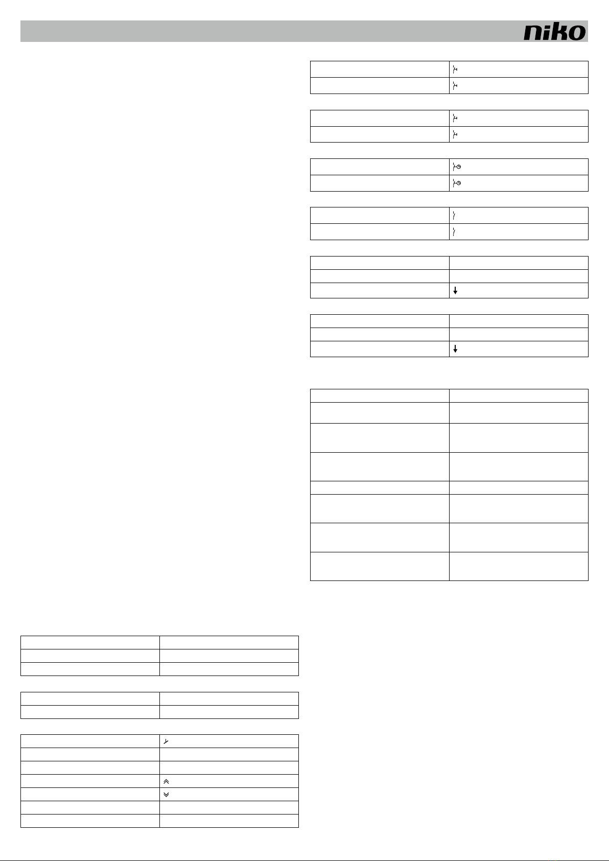
4.2. Anwendungen
Anwendung 30.01 (z.B. Flure) = Dreikanal-Tageslichtdimmung, automatisch ein/aus über Bewegungsmelder
Die Tageslichtsteuerung wird eingeschaltet, wenn der Bewegungsmelder eine Aktivität erfasst und wenn
Beleuchtung erforderlich ist. Solange der Bewegungsmelder eine Aktivität erfasst, wird auf Grundlage
der eingestellten Parameter und abhängig vom einfallenden Tageslicht die Beleuchtung über drei
Kanäle gedimmt. Nimmt die Menge des einfallenden Tageslichts zu, dann wird die Beleuchtung solange
heruntergedimmt, bis die eingestellte Mindest-Beleuchtungsstärke erreicht ist. Die Beleuchtung wird
automatisch nach einer voreingestellten Zeit ausgeschaltet, sobald der Bewegungsmelder keine Aktivität
mehr im Erfassungsbereich registriert oder wenn die Beleuchtungsstärke ausreichend hoch ist (Cut-Off).
Option für manuelles ein/aus (kurz betätigen) (I/O) und manuelles Dimmen (lang betätigen) ( und )
mittels Niederspannungsschalter.
Anwendung 31.01 (z.B. für Ausstellungsräume) = DreiKanal-Tageslichtdimmung, regelbar über eine externe
Zeitschaltuhr ( )
Die Tageslichtsteuerung wird über eine externe Zeitschaltuhr ein- und ausgeschaltet. Auf Grundlage
der eingestellten Parameter und abhängig vom einfallenden Tageslicht wird die Beleuchtung über drei
Kanäle gedimmt. Nimmt die Menge des einfallenden Tageslichts zu, dann wird die Beleuchtung solange
heruntergedimmt, bis die eingestellte Mindest-Beleuchtungsstärke erreicht ist. Die Beleuchtung wird
automatisch ausgeschaltet, sobald die Beleuchtungsstärke ausreichend hoch ist (Cut-Off), oder über eine
externe Zeitschaltuhr.
Option für manuelles ein/aus (kurz betätigen) (I/O) und manuelles Dimmen (lang betätigen) ( und )
mittels Niederspannungsschalter.
Anwendung 32.01 (z.B. Bürogebäude und Konferenzräume) = Dreikanal-Tageslichtdimmung, manuell ein/
aus, automatisch aus über Bewegungsmelder
Die Tageslichtsteuerung wird über einen Niederspannungsschalter ( ) ein- und ausgeschaltet. Solange
der Bewegungsmelder eine Aktivität erfasst, wird auf Grundlage der eingestellten Parameter und abhängig
vom einfallenden Tageslicht die Beleuchtung über drei Kanäle gedimmt. Nimmt die Menge des einfallenden
Tageslichts zu, dann wird die Beleuchtung solange heruntergedimmt, bis die eingestellte Mindest-
Beleuchtungsstärke erreicht ist. Die Beleuchtung wird automatisch nach einer voreingestellten Zeit
ausgeschaltet, sobald der Bewegungsmelder keine Aktivität mehr im Erfassungsbereich registriert oder
wenn die Beleuchtungsstärke ausreichend hoch ist (Cut-Off).
Option für manuelles ein/aus (kurz betätigen) (I/O) und manuelles Dimmen (lang betätigen) ( und )
mittels Niederspannungsschalter.
Anwendung 33.01 (z.B. Schulungsräume) = Zweikanal-Tageslichtdimmung, Einkanal-Tageslichtdimmung
ein/aus über Bewegungsmelder, manuell ein/aus, automatisch aus über Bewegungsmelder
a. Allgemeine Beleuchtung
Die Zweikanal-Tageslichtsteuerung (Kanal 1 und 2) wird über einen Niederspannungsschalter ( )
ein- und ausgeschaltet (neben der Tür). Solange der Bewegungsmelder eine Aktivität erfasst, wird auf
Grundlage der eingestellten Parameter und abhängig vom einfallenden Tageslicht die Beleuchtung
über zwei Kanäle (Kanal 1 und 2) gedimmt. Nimmt die Menge des einfallenden Tageslichts zu, dann
wird die Beleuchtung solange heruntergedimmt, bis die eingestellte Mindest-Beleuchtungsstärke
erreicht ist. Die Beleuchtung wird automatisch nach einer voreingestellten Zeit ausgeschaltet,
sobald der Bewegungsmelder keine Aktivität mehr im Erfassungsbereich registriert oder wenn die
Beleuchtungsstärke ausreichend hoch ist (Cut-Off).
Option für manuelles ein/aus (kurz betätigen) (I/O) und manuelles Dimmen (lang betätigen) ( und )
mittels Niederspannungsschalter.
Die Beleuchtung wird ausschließlich in Zone 1 und 2 gedimmt.
b.Schilderbeleuchtung
Die Einkanal-Tageslichtsteuerung (Kanal 3) wird über einen Niederspannungsschalter ( ) ein- und
ausgeschaltet (Schild). Die Beleuchtung bleibt eingeschaltet, solange der Bewegungsmelder eine
Aktivität erfasst. Die Beleuchtung wird automatisch nach einer voreingestellten Zeit ausgeschaltet,
sobald der Bewegungsmelder keine Aktivität mehr erfasst. Wenn die allgemeine Beleuchtung über den
an der Tür befindlichen Niederspannungsschalter ausgeschaltet wird, wird auch die Schilderbeleuchtung
ausgeschaltet.
Ist für die Schilderbeleuchtung kein DALI-Vorschaltgerät vorgesehen, müssen die
Beleuchtungseinrichtungen (230 V) an Kanal 3 angeschlossen und darf nur vom Netzteil für das
Tageslichtsteuerungsmodul (360-47000) versorgt werden.
Soll die Schilderbeleuchtung mit der DALI-Ein-/Ausfunktion angesteuert werden, müssen die
Beleuchtungseinrichtungen Zone 3 und Kanal 1 zugewiesen werden.
Anwendung 34.01 (z.B. Produktionshallen) = Dreikanal-Tageslichtdimmung, manuell ein/aus über
Drucktaster oder Schalter, automatisch aus über eine externe Zeitschaltuhr ( )
Die Tageslichtsteuerung wird über einen Niederspannungsschalter ein- und ausgeschaltet. Die
Beleuchtung wird auf Grundlage der eingestellten Parameter von der Tageslichtsteuerung über drei
Kanäle angesteuert. Nimmt die Menge des einfallenden Tageslichts zu, dann wird die Beleuchtung
solange heruntergedimmt, bis die eingestellte Mindest-Beleuchtungsstärke erreicht ist. Die Beleuchtung
wird automatisch ausgeschaltet, sobald die Beleuchtungsstärke ausreichend hoch ist (Cut-Off), oder
über eine externe Zeitschaltuhr.
Option für manuelles ein/aus (kurz betätigen) (I/O) und manuelles Dimmen (lang betätigen) ( und )
mittels Niederspannungsschalter.
5. PFLEGE
Schmutz kann die Funktion des angeschlossenen Bewegungsmelders beeinträchtigen. Halten Sie deswegen
immer die Linse sauber und trocken. Benutzen Sie für die Linsenreinigung ein feuchtes Tuch mit Wasser
und nur wenig Reinigungsmittel. Üben Sie beim Reinigen niemals Druck auf die Linse aus. Sind Linse oder
andere Komponenten des Bewegungsmelders defekt, dann nehmen Sie Kontakt zu einem qualifizierten
Elektroinstallateur auf.
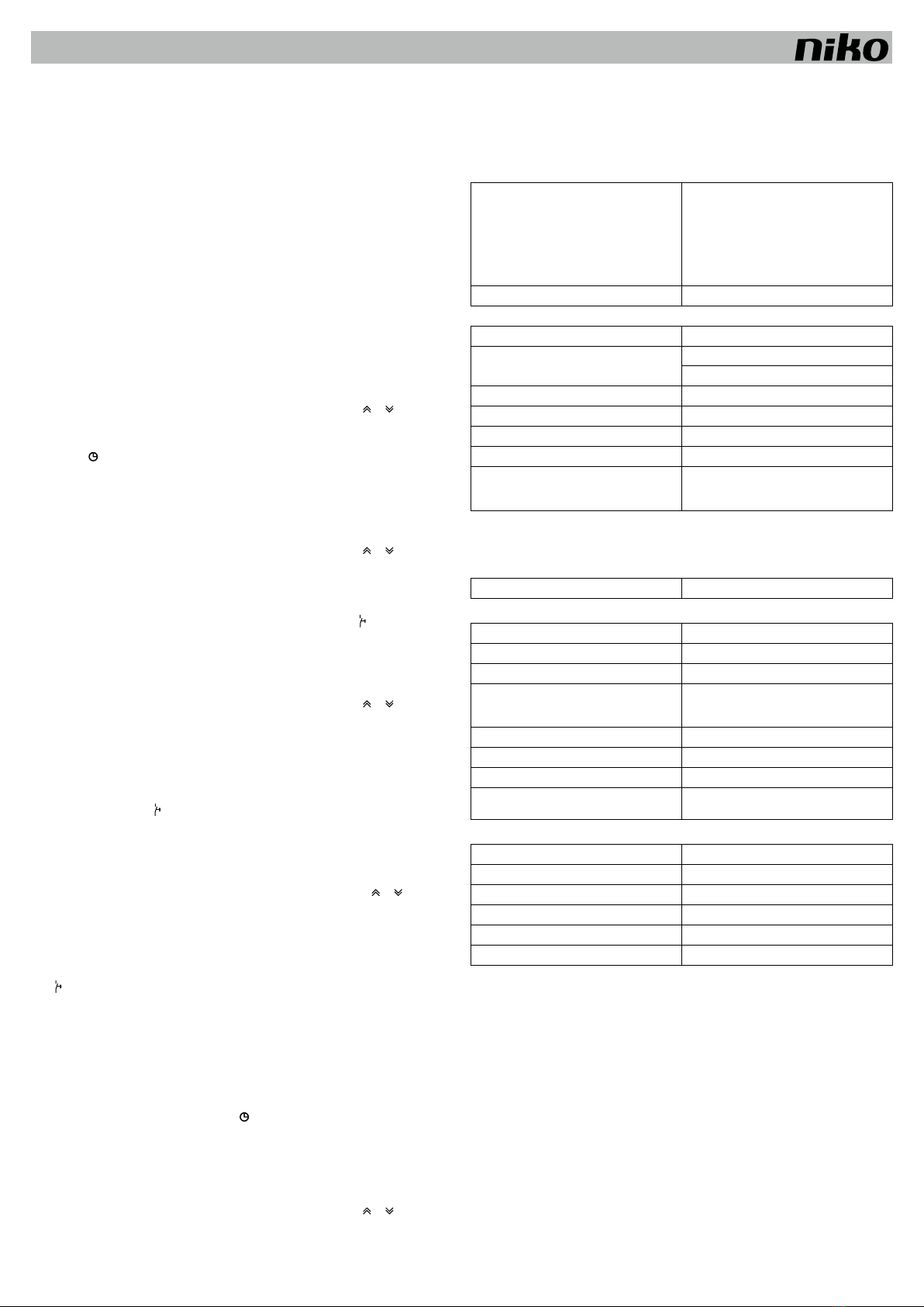
6. TECHNISCHE DATEN
RJ12-1
Pin 1 und Pin 2
Pin 1 – Netzteil
Pin 2 – Netzteil
Pin 3 – I/O
Pin 4 – Kanal 1
Pin 5 – Kanal 2
Pin 6 – Kanal 3
24 Vdc ± 10% (SELV)
+
-
offener Anschluss
NPN 24 V/25 mA – versehen mit Schutz gegen Kurzschluss
RJ12-2 Für Softwareupdate. Darf nicht verwendet werden.
Abmessungen (4 DIN-Schienenmodule) 90 x 70 x 55 mm (HxBxT)
Leistungsaufnahme in Betrieb: 6 VA
im Standby-Betrieb: 2 VA
Umgebungstemperatur 5 – 50°C
Lagertemperatur -20 – +60°C
Schutzart IP20
Prüfzeichen CE-Kennzeichnung gemäß EN 60669-2-1
Zubehör Bewegungsmelder (24 Vdc)
Lichtmesszelle (350-1001X)
Netzteil für Tageslichtsteuerungsmodul (360-47000)
7. ABKÜRZUNGSVERZEICHNIS
7.1. Abkürzungen des Displaymenüs
Unter Menüpunkt General:
App. Anwendung
Unter Menüpunkt Adjustment:
Lx ind1 Lux indoors 1: “gemessene” Beleuchtungsstärke von Zone 1
Lx ind2 Lux indoors 2: “gemessene” Beleuchtungsstärke von Zone 2
Lx ind3 Lux indoors 3: “gemessene” Beleuchtungsstärke von Zone 3
Sensor Beleuchtungsstärke pro Lichtmesszelle, wird zur Berechnung
des Tageslichtfaktors verwendet, wird automatisch ausgeführt
Setp1 Einstellpunkt 1: Sollwert der Lichtniveau von Zone 1
Setp2 Einstellpunkt 2: Sollwert der Lichtniveau von Zone 2
Setp3 Einstellpunkt 3: Sollwert der Lichtniveau von Zone 3
Off delay allgemeine Ausschaltverzögerung, bevor der Bewegungsmelder
abschaltet
Unter Menüpunkt Status:
Ch1 Kanal 1
Ch2 Kanal 2
Ch3 Kanal 3
Df1 Tageslichtfaktor 1: Verhältnis zwischen Lx ind1 und Sensor
Df2 Tageslichtfaktor 2: Verhältnis zwischen Lx ind2 und Sensor
Df3 Tageslichtfaktor 3: Verhältnis zwischen Lx ind3 und Sensor
7.2. Displaymenü-Terminologie
Assigned
Zone 1, 2 oder 3 zugewiesene Beleuchtungseinrichtungen. Auf Wunsch können die
Beleuchtungseinrichtungen einer neuen Zone zugewiesen werden.
Not assigned
Beleuchtungseinrichtungen, die keiner Zone zugewiesen sind. Weisen Sie die Beleuchtungseinrichtungen
Zone 1, 2 oder 3 zu.
Fade factor
Wählen Sie hier die Übergangszeit (Fade) für die Beleuchtungseinrichtungen aus. Flackern die
Beleuchtungseinrichtungen während der Übergangsphase, dann muss der Fade-Faktor erhöht werden.
Cut off PS
Ausschaltverzögerung für Cut-Off-Funktion, die das Netzteil für alle Beleuchtungseinrichtungen abschaltet.

360-45012
DE nv Niko sa Industriepark West 40, BE-9100 Sint-Niklaas, Belgium — tel. +32 3 778 90 00 — fax +32 3 777 71 20 — e-mail: [email protected] — www.niko.eu PM360-45012R12412
Power on
Einschalt-Beleuchtungsstärke der Beleuchtungseinrichtungen, wenn der DALI-Bus zum ersten Mal vom
Controller mit Spannung versorgt wird.
Failure LVL
Einschalt-Beleuchtungsstärke der Beleuchtungseinrichtungen, wenn der DALI-Bus nicht mit Spannung
versorgt wird.
Search new ID
Diese Funktion führt eine Suche nach Beleuchtungseinrichtungen aus und weist diesen eine ID-Adresse zu.
Reset units
Rücksetzen der Parameter (Fade factor,Power on,Failure LVL) und Löschen der Zonenzuweisung. Trifft für
alle am DALI-Bus angeschlossenen Beleuchtungseinrichtungen zu.
Randomize ID
Löscht alle ID-Adressen und setzt alle Parameter der ausgewählten Beleuchtungseinrichtungen auf die
Werkseinstellungen zurück.
Randomize units
Löscht alle ID-Adressen und setzt alle Parameter der am DALI-Bus angeschlossenen
Beleuchtungseinrichtungen auf die Werkseinstellungen zurück.
8. WARNHINWEISE FÜR DIE INSTALLATION
- Die Installation darf ausschließlich von einer Elektrofachkraft unter Berücksichtigung der geltenden
Vorschriften ausgeführt werden.
- Diese Gebrauchsanleitung muss dem Benutzer ausgehändigt werden. Die Gebrauchsanleitung ist den
Unterlagen der elektrischen Anlage beizufügen und muss auch eventuellen neuen Besitzern ausgehändigt
werden. Zusätzliche Exemplare erhalten Sie über die Internetseiten von Niko oder über den Kundendienst von
Niko.
- Beachten und berücksichtigen Sie bei der Installation unter anderem folgende Punkte:
- die gültigen Gesetze, Normen und Richtlinien.
- den Stand der Technik zum Zeitpunkt der Installation.
- die in dieser Gebrauchsanleitung aufgeführten Anweisungen, wobei diese Gebrauchsanleitung nur
allgemein gültige Bestimmungen enthält, die für jede Anlage spezifisch angewendet werden müssen.
- die allgemein anerkannten Regeln fachmännischer Arbeit.
Dieses Produkt erfüllt alle anwendbaren europäischen Richtlinien und Verordnungen. Die für dieses Produkt
zutreffende EG-Konformitätserklärung erhalten Sie gegebenenfalls unter www.niko.eu.
9. NIKO UNTERSTÜTZUNG
Bei Zweifel oder falls Sie bei einem eventuellen Defekt des Produkts noch Fragen bezüglich des Umtausches
haben, dann nehmen Sie bitte Kontakt auf mit dem Kundendienst von Niko (Belgien: +32 3 778 90 80) oder
wenden Sie sich an Ihren Großhändler. Kontaktdaten und weitere Informationen erhalten Sie im Internet unter
www.niko.eu in der Rubrik “Unterstützung und Beratung”.
10. GARANTIEBEDINGUNGEN
- Der Garantiezeitraum beträgt vier Jahre ab Lieferdatum. Als Lieferdatum gilt das Rechnungsdatum
zum Zeitpunkt des Kaufs durch den Endverbraucher. Falls keine Rechnung mehr vorhanden ist, gilt das
Produktionsdatum.
- Der Endverbraucher ist verpflichtet, Niko schriftlich über einen Produktmangel innerhalb von zwei Monaten
nach dessen Feststellung zu informieren.
- Im Falle eines Mangels hat der Endverbraucher nur Recht auf kostenlose Reparatur oder Ersatz des Produkts.
Eine Entscheidung darüber obliegt allein Niko.
- Niko ist nicht für Mängel oder Schäden verantwortlich, die durch fehlerhafte Installation, nicht
bestimmungsgemäßen oder unsachgemäßen Gebrauch, durch falsche Bedienung, Anpassen/Ändern des
Produktes, infolge von unsachgemäßer Wartung entgegen den Wartungsvorschriften oder die sich aus
äußeren Umständen, wie beispielsweise infolge Feuchtigkeit oder Überspannung, ergeben.
- Zwingende Vorschriften der nationalen Gesetzgebung bezüglich des Verkaufs von Konsumgütern und zum
Verbraucherschutz haben vor den obigen Bestimmungen Vorrang in den Ländern, in denen Niko direkt oder
über seine Neben- oder Tochtergesellschaften, Filialen, Vertriebsstellen, Agenten oder über feste Vertreter
verkauft.

360-45012
EN nv Niko sa Industriepark West 40, BE-9100 Sint-Niklaas, Belgium — tel. +32 3 778 90 00 — fax +32 3 777 71 20 — e-mail: [email protected] — www.niko.eu PM360-45012R12412
Read the complete user manual before carrying out the installation and activating the system.
1. DESCRIPTION
The Luxstat Control DALI daylight control module (dimmable) regulates all low-voltage input signals from
sensors and switches which are directly connected to the controller.
A DALI bus for light fittings is also directly connected to the daylight control module. This bus is equipped with
a power supply and communication protocol for the addressable DALI components, so that each light fitting
has a unique ID address.
The daylight control module is suitable for DIN-rail mounting.
The daylight control module can control a maximum of 64 individual fittings that are equipped with DALI
ballasts. These ballasts can be distributed via the ID addresses over a maximum of three zones for daylight-
dependent control.
DALI light fittings are directly connected via a two-wire DALI bus to the daylight control module, which the
DALI bus supplies with 15 Vdc.
The power supply for the daylight control module (360-47000) (safety extra-low voltage or SELV) is used to
control the 230 V output to the light fittings and the switch-off delay. The power supply is suitable for DIN-rail
mounting.
The daylight control module contains a number of applications that are preprogrammed standard and which
can be easily selected using the integrated display.
If the daylight control module is connected to a photo cell (350-1001X) and a motion detector, if the detector
detects activity and if lighting is needed, application 30.01 (factory setting) ensures that the lighting is
switched on and the lighting level is regulated depending on the incoming daylight.
Lighting control can be useful in for example corridors, exhibition rooms, office buildings, meeting rooms,
classrooms, production halls, cafeterias, sport halls, foyers and warehouses.
2. INSTALLATION
2.1. General
Attention: To be performed before activating the daylight control module.
Refer to the wiring diagram (fig. 1 – 9).
Before activating the daylight control module, the photo cell, push button or switch, motion detector and DALI
light fittings must be correctly assembled and connected.
Refer to the installation menu (fig. 10):
1. Start up the system.
2.Accept the sensor value on the display.
3.Start up the daylight control module.
4.Select Randomize units from the display menu to ensure that all light fittings are ready for Search new ID.
Via the Search new ID display menu, each DALI light fitting is localised on the DALI bus and a unique
ID address is assigned to each fitting. It takes approximately 15 seconds to assign one ID address. For
example, for 64 fittings, this process takes approximately 16 minutes.
5.Go to the Not assigned display menu
Using the ID address, assign the lighting zone to each DALI light fitting on the DALI bus to which it belongs:
zone 1, zone 2 or zone 3.
When you assign a light fitting to a zone, the lighting from that fitting is automatically switched on so that
you can see which fitting is being configured.
The daylight control module is now ready to be used with the factory settings.
If you activate the daylight control module before you have correctly assembled and connected the photo cell,
you may have to perform the initialisation again via: ADJUSTMENT > Adjust Settings > Initiate Sensor.
2.2. Connecting accessories
Power supply for photo cell/motion detector (general):
power supply 24 Vdc ± 10%, max. 100 mA
ø B1/A11 +
ø B2/A7/A12 -
DALI ballast, via DALI bus with two-wire conductor:
ø D3 0 Vdc and communication
ø D4 15 Vdc ± 20% and communication
Low-voltage push button:
ø B2
ø B3 Auto
ø B4 I/O
ø B5
ø B6
ø B7 LED Auto
ø B8 LED I/O
Low-voltage switch (door):
ø B2
ø B9
Low-voltage switch (blackboard):
ø B2
ø B10
Time switch:
ø B2
ø B11
Energy-saving contact (load switch-off):
ø A12
ø B12
Motion detector, NPN:
ø A11 +
ø A12 -
ø A9
Photo cell:
ø A11 +
ø A12 -
ø A10
3. SETTINGS
3.1. Factory settings
Parameter Setting
application 30.01, automatic on/off via motion detector
indoor light intensity Lx ind1 = 200 lux
Lx ind2 = 160 lux
Lx ind3 = 100 lux
light sensitivity Setp1 = 300 lux
Setp2 = 300 lux
Setp3 = 300 lux
switch-off delay 10 min
minimum lighting level Light min1 = 0%
Light min2 = 0%
Light min3 = 0%
maximum lighting level Light max1 = 100%
Light max2 = 100%
Light max3 = 100%
load switch-off Loadshed1 = 50%
Loadshed2 = 50%
Loadshed3 = 50%
You can use the daylight control module with the factory settings.
For optimal use, it is recommended that the settings will be adjusted to the lighting conditions in the area using
the menu and the display on the daylight control module.
3.2. Changing the settings
1.Decide which lighting level and light sensitivity (set point) are needed for the area within each zone: Setp1,
Setp2,Setp3.
2.Switch off the lighting and measure the lighting level at table height in each zone using a lux meter:
Lx ind1, Lx ind2,Lx ind3.
3.Start up the daylight control module and wait a moment.
The daylight control module must be correctly connected to a photo cell.
4.Select the correct application (see section 4.2.) and number of channels (Ch).
5.Go to the Daylight Factor menu and set the following parameters:
•Range: With an indoor photo cell mounted on the ceiling in the vicinity of a window, the factory setting
30 – 3000 lux is recommended. With an indoor photo cell mounted in a skylight or velux window,
300 – 30 000 lux is recommended. The setting on the daylight control module and the photo cell must
be within the same range.
•Lx ind: Enter the measured lux values (Lx ind1,Lx ind2,Lx ind3). See step 2.
•Sensor: Press ADJ (current lux value read off in the menu). If the read-off lux value is higher than the
highest lux value in the Lx ind1,Lx ind2 and Lx ind3 menu, press Save.
This is how the daylight control module automatically calculates the parameters for an optimal lighting
control in the areas.

360-45012
EN nv Niko sa Industriepark West 40, BE-9100 Sint-Niklaas, Belgium — tel. +32 3 778 90 00 — fax +32 3 777 71 20 — e-mail: [email protected] — www.niko.eu PM360-45012R12412
6.Complete the daylight control module documentation with the set parameters. Refer to the enclosed
document (“Project planning”).
Refer to figure 11 to select the daylight factor settings.
3.3. Protection mode
For extra protection against unwanted changes to the daylight control module, it is recommended to make a
copy of the user settings as a back-up. Select Run in back-up mode.
4. OPERATION AND USE
4.1. Initial activation
The initial activation takes preferably place on a day when there is sufficient daylight and at a moment
when little direct sunlight is reaching the area. The following settings are a good starting point for the initial
activation: indoor lux value (Lx ind1,Lx ind2,Lx ind3) higher than 50 lux and lower than 1000 lux, measured
with a lux meter.
4.2. Applications
Application 30.01 (e.g. corridors) = three-channel daylight dimming, automatic on/off via a motion detector
The daylight control is switched on if the motion detector detects activity and if lighting is needed. As
long as the motion detector detects activity, the lighting is dimmed in three channels according to the set
parameters and depending on the incoming daylight. As the amount of incoming daylight increases, the
lighting is dimmed until the preset minimum lighting level is reached. The lighting is automatically switched
off after a preset time period as soon as the motion detector no longer detects any activity in the detection
area or the lighting level is sufficiently high (cut-off).
Option for manual on/off (brief press) (I/O) and manual dimming (long press) ( and )via a low-voltage
switch.
Application 31.01 (e.g. exhibition rooms) = three-channel daylight dimming, can be regulated via an
external time switch ( )
The daylight control is switched on and off via an external time switch. The lighting is dimmed in three
channels according to the set parameters and depending on the incoming daylight. As the amount of
incoming daylight increases, the lighting is dimmed until the preset minimum lighting level is reached.
The lighting is automatically switched off as soon as the lighting level is sufficiently high (cut-off), or via an
external time switch.
Option for manual on/off (brief press) (I/O) and manual dimming (long press) ( and ) via a low-voltage
switch.
Application 32.01 (e.g. office buildings and meeting rooms) = three-channel daylight dimming, manual on/
off, automatic off via a motion detector
The daylight control is switched on and off via a low-voltage switch ( ). As long as the motion detector
detects activity, the lighting is dimmed in three channels according to the set parameters and depending
on the incoming daylight. As the amount of incoming daylight increases, the lighting is dimmed until the
preset minimum lighting level is reached. The lighting is automatically switched off after a preset time
period as soon as the motion detector no longer detects any activity in the detection area or if the lighting
level is sufficiently high (cut-off).
Option for manual on/off (brief press) (I/O) and manual dimming (long press) ( and ) via a low-voltage
switch.
Application 33.01 (e.g. classrooms) = two-channel daylight dimming, single-channel daylight dimming on/off
via motion detector, manual on/off, automatic off via a motion detector
a. General lighting
The two-channel daylight control (channels 1 and 2) is switched on and off via a low-voltage switch ( )
(next to the door). As long as the motion detector detects activity, the lighting is dimmed in two channels
(channels 1 and 2) according to the set parameters and depending on the incoming daylight. As the
amount of incoming daylight increases, the lighting is dimmed until the preset minimum lighting level
is reached. The lighting is automatically switched off after a preset time period as soon as the motion
detector no longer detects any activity in the detection area or if the lighting level is sufficiently high
(cut-off).
Option for manual on/off (brief press) (I/O) and manual dimming (long press) ( and ) via a low-voltage
switch.
The lighting can only be dimmed in zones 1 and 2.
b.Blackboard lighting
The single-channel daylight control (channel 3) is switched on and off via a low-voltage switch ( )
(blackboard). As long as the motion detector detects activity, the lighting remains on. The lighting is
automatically switched off after a preset time period as soon as the motion detector no longer detects
any activity. If the general lighting is switched off via a low-voltage switch at the door, the blackboard
lighting is also switched off.
If no DALI ballast is provided for the blackboard lighting, the light fittings (230 V) must be connected to
channel 3 and only to the power supply for the daylight control module (360-47000).
If the board lighting must be regulated via DALI on/off, the light fittings must be assigned to zone 3 and
channel 1
Application 34.01 (e.g. production halls) = three-channel daylight dimming, manual on/off via push button
or switch, automatic off via an external time switch ( )
The daylight control is switched on and off via a low-voltage switch. The lighting is regulated by daylight
control in three channels according to the set parameters. As the amount of incoming daylight increases,
the lighting is dimmed until the preset minimum lighting level is reached. The lighting is automatically
switched off as soon as the lighting level is sufficiently high (cut-off), or via an external time switch.
Option for manual on/off (brief press) (I/O) and manual dimming (long press) ( and ) via a low-voltage
switch.
5. MAINTENANCE
Dirt may prevent the connected motion detector from functioning properly. Therefore, always keep the lens
clean and dry. Use a damp cloth and water with some detergent to clean the lens. Never exert pressure
to wipe the lens clean. If the lens or other parts of the motion detector are defective, please contact an
authorised installer.
6. TECHNICAL DATA
RJ12-1
pin 1 and pin 2
pin 1 – power supply
pin 2 – power supply
pin 3 – I/O
pin 4 – channel 1
pin 5 – channel 2
pin 6 – channel 3
24 Vdc ± 10% (SELV)
+
-
open connection
NPN 24 V/25 mA – protected against short-circuit
RJ12-2 For software update. Must not be used.
dimensions (4 DIN rail modules) 90 x 70 x 55 mm (HxWxD)
power consumption in operation: 6 VA
stand-by: 2 VA
ambient temperature 5 – 50°C
storage temperature -20 – +60°C
protection degree IP20
quality mark CE marked in accordance with EN 60669-2-1
accessories motion detector (24 Vdc)
photo cell (350-1001X)
power supply for the daylight control module (360-47000)
7. EXPLANATION OF TERMINOLOGY
7.1. Abbreviations on the display menu
Under General:
App. application
Under Adjustment:
Lx ind1 Lux indoors 1: “measured” lighting level in zone 1
Lx ind2 Lux indoors 2: “measured” lighting level in zone 2
Lx ind3 Lux indoors 3: “measured” lighting level in zone 3
Sensor lighting level per photo cell, used to calculate the daylight
factor, performed automatically
Setp1 set point 1: required lighting level in zone 1
Setp2 set point 2: required lighting level in zone 2
Setp3 set point 3: required lighting level in zone 3
Off delay generalswitch-offdelaybeforethemotiondetectorisswitchedoff
Under Status:
Ch1 channel 1
Ch2 channel 2
Ch3 channel 3
Df1 daylight factor 1: ratio between Lx ind1 and Sensor
Df2 daylight factor 2: ratio between Lx ind2 and Sensor
Df3 daylight factor 3: ratio between Lx ind3 and Sensor
7.2. Terminology on the display menu
Assigned
The light fittings which are assigned to zone 1, 2 or 3. The light fittings can be assigned to a new zone, if
desired.
Not assigned
The light fittings which are not assigned to a zone. Assign the light fittings to zone 1, 2 or 3.
Fade factor
Select the desired transition time (fade) for the light fittings here. The fade factor must be increased if the light
fittings flicker during the transition phase.
Cut off PS
The switch-off delay for cut-off, which switches off the power supply to all light fittings.
Power on
The lighting level at which the light fittings are switched on when the DALI bus is powered on by the controller
for the first time.
Failure LVL
The lighting level at which the light fittings are switched on when the DALI bus is not powered on.
Search new ID
This function searches for light fittings and assigns an ID address to each fitting.

360-45012
EN nv Niko sa Industriepark West 40, BE-9100 Sint-Niklaas, Belgium — tel. +32 3 778 90 00 — fax +32 3 777 71 20 — e-mail: [email protected] — www.niko.eu PM360-45012R12412
Reset units
Resets the parameters (Fade factor,Power on,Failure LVL) and deletes the zone assignments. Applicable to
all light fittings on the DALI bus.
Randomize ID
Deletes the ID addresses and resets all parameters of the selected light fittings to the factory settings.
Randomize units
Deletes the ID addresses and resets all parameters of all light fittings on the DALI bus to the factory settings.
8. WARNINGS REGARDING INSTALLATION
- The installation should be carried out by a registered installer and in compliance with the statutory regulations.
- This user manual should be presented to the user. It should be included in the electrical installation file, and
it should be passed on to any new owners. Additional copies are available on the Niko website or via the Niko
support service.
- During installation, the following should be taken into account (non-exhaustive list):
- the statutory laws, standards and regulations.
- the technology currently available at the time of installation.
- this user manual, which only states general regulations and should therefore be read within the scope of
each specific installation.
- the rules of proper workmanship.
This product complies with all of the relevant European guidelines and regulations. If applicable, you can find
the EC declaration of conformity regarding this product at www.niko.eu.
9. NIKO SUPPORT
In case of doubt or for the specific exchange procedure in case of a possible defect, contact the Niko support
service in Belgium at +32 3 778 90 80 or your wholesaler/installer. Contact details and more information can
be found at www.niko.eu under the “Help and advice” section.
10. GUARANTEE PROVISIONS
- The period of guarantee is four years from the date of delivery. The delivery date is the invoice date of
purchase of the product by the consumer. If there is no invoice, the date of production applies.
- The consumer is obliged to inform Niko in writing about the non-conformity, within two months after stating
the defect.
- In case of a non-conformity, the consumer only has the right to a product repair or replacement free of charge,
which shall be decided by Niko.
- Niko shall not be held liable for a defect or damage resulting from incorrect installation, improper or careless
use, incorrect operation, transformation of the product, maintenance that does not adhere to the maintenance
instructions or an external cause, such as damage due to moisture or overvoltage.
- The compulsory regulations of the national legislation concerning the sale of consumer goods and the
protection of the consumer in the countries where Niko sells, directly or via sister companies, subsidiaries,
chain stores, distributors, agents or permanent sales representatives, take priority over the above-mentioned
rules and regulations.

360-45012
SK nv Niko sa Industriepark West 40, BE-9100 Sint-Niklaas, Belgium — tel. +32 3 778 90 00 — fax +32 3 777 71 20 — e-mail: [email protected] — www.niko.eu PM360-45012R12412
Pred vykonaním inštalácie a aktiváciou systému si prečítajte celý návod.
1. POPIS
Svetelný regulátor Luxstat Control DALI s funkciou stmievania reguluje všetky nízkonapäťové vstupné
signály zo snímačov a spínačov, ktoré sú pripojené priamo k svetelnému regulátoru.
Zbernica DALI pre svietidlá je taktiež priamo pripojená k svetelnému regulátoru. Zbernica je vybavená
napájacím zdrojom a komunikačným protokolom pre adresovateľné DALI komponenty, takže každé svietidlo
ma unikátnu ID adresu.
Svetelný regulátor je vhodný pre montáž na DIN lištu.
Svetelný regulátor môže ovládať maximálne 64 samostatných svietidiel, ktoré sú vybavené DALI predradníkmy.
Predradníky je možné rozdeliť pomocou ID adries na maximálne tri zóny ovládané v závislosti od denného svetla.
Svietidlá DALI sú priamo pripojené cez 2-vodičovú DALI zbernicu k svetelnému regulátoru denného svetla,
ktorý zbernicu napája s 15 Vdc.
Napájanie pre svetelný regulátor (360-47000) (bezpečné nízke napätie alebo SELV) sa používa na ovládanie
230 V výstupu k svietidlám a oneskorenia vypnutia. Napájací zdroj je vhodný pre montáž na DIN lištu.
Svetelný regulátor obsahuje viacero aplikácii, ktoré sú vopred naprogramované a ktoré je možné jednoducho
zvoliť pomocou integrovaného displeja.
Ak je svetelný regulátor pripojení ku svetelnému senzoru (350-1001X) a detektoru pohybu a ak detektor
deteguje aktivitu a osvetlenie je potrebné, aplikácia 30.01 (továrenské nastavenia) zaisťuje, že osvetlenia sa
zapne a intenzita osvetlenia je regulovaná v závislosti od intenzity denného svetla.
Ovládanie osvetlenia môže byť užitočné napríklad v chodbách, výstavných miestnostiach, kanceláriách,
zasadacích miestnostiach, výrobných halách, kaviarňach, športových halách, vestibuloch alebo skladoch.
2. INŠTALÁCIA
2.1. Všeobecné
Pozor: Vykonať pred aktiváciou svetelného regulátora.
Pozrite schému zapojenia (obr. 1 – 9).
Pred aktivovaným svetelného regulátora musia byť svetelný senzor, tlačidlo alebo spínač, detektor pohybu a
svietidlá DALI správne osadené a zapojené.
Pozrite časť inštalácia (obr. 10):
1. Spustenie systému.
2.Potvrďte hodnoty senzora na displeji.
3.Spustenie svetelného regulátora.
4.Z menu zobrazenia zvoľte Randomize units aby ste sa uistili, že všetky svietidlá sú pripravené na
Search new ID.
Pomocou položky menu Search new ID, sa každému DALI svietidlu, ktoré sa nachádza na DALI zbernici
priradí unikátna ID adresa. Proces priradenia jednej ID adresy trvá približne 15 sekúnd. Napríklad pri 64
svietidlách trvá proces približne 16 minút.
5.Prejdite na položku menu Not assigned.
Pomocou ID adresy priraďte pre každé DALI svietidlo na DALI zbernici svetelnú zónu ku ktorej patrí: zóna 1,
zóna 2 alebo zóna 3.
Po priradení svietidla k zóne sa svetlo z daného svietidla automaticky zapne, aby ste videli, ktoré svietidlo
sa práve konfiguruje.
Svetelný regulátor je teraz pripravený na použitie s továrenskými nastaveniami.
Ak aktivujete svetelný regulátor predtým, ako ste správne nainštalovali a zapojili svetelný senzor, musíte
opätovne vykonať inicializáciu pomocou: ADJUSTMENT > Adjust Settings > Initiate Sensor.
2.2. Pripojenie príslušenstva
Napájací zdroj pre svetelný senzor/detektor pohybu (všeobecne):
napájací zdroj 24 Vdc ± 10%, max. 100 mA
ø B1/A11 +
ø B2/A7/A12 -
DALI predradník, pomocou 2-vodičovej DALI zbernice:
ø D3 0 Vdc a komunikácia
ø D4 15 Vdc ± 20% a komunikácia
Nízkonapäťové tlačidlo:
ø B2
ø B3 Auto
ø B4 I/O
ø B5
ø B6
ø B7 LED Auto
ø B8 LED I/O
Nízkonapäťový spínač (dvere):
ø B2
ø B9
Nízkonapäťový spínač (tabuľa):
ø B2
ø B10
Časový spínač:
ø B2
ø B11
Energeticky úsporný kontakt (vypnutie záťaže):
ø A12
ø B12
Detektor pohybu, NPN:
ø A11 +
ø A12 -
ø A9
Svetelný senzor:
ø A11 +
ø A12 -
ø A10
3. NASTAVENIA
3.1. Továrenské nastavenia
Parameter Nastavenia
použitie 30.01, automatické zapnutie/vypnutie
prostredníctvom detektora pohybu
vnútorná intenzita osvetlenia Lx ind1 = 200 lux
Lx ind2 = 160 lux
Lx ind3 = 100 lux
svetelná citlivosť Setp1 = 300 lux
Setp2 = 300 lux
Setp3 = 300 lux
doba oneskorenia vypnutia 10 minút
minimálna intenzita osvetlenia Light min1 = 0%
Light min2 = 0%
Light min3 = 0%
maximálna intenzita osvetlenia Light max1 = 100%
Light max2 = 100%
Light max3 = 100%
vypnutie záťaže Loadshed1 = 50%
Loadshed2 = 50%
Loadshed3 = 50%
Svetelný regulátor môžete použiť aj s továrenskými nastaveniami.
Pre optimálne využitie sa však odporúča, aby ste nastavenie prispôsobili ku svetelným podmienkam v oblasti
pomocou menu a displeja na svetelnom regulátore.
3.2. Zmena nastavení
1.Rozhodnite sa, aká intenzita osvetlenia a svetelná citlivosť (set point) je potrebná pre oblasť v danej zóne:
Setp1,Setp2,Setp3.
2.Vypnite osvetlenie a pomocou luxmetra zmerajte v každej zóne intenzitu osvetlenia vo výške stola: Lx ind1,
Lx ind2,Lx ind3.
3.Zapnite svetelný regulátor a chvíľku počkajte.
Svetelný regulátor musí byť správne pripojený ku svetelnému senzoru.
4.Vyberte správnu aplikáciu (pozrite kapitolu 4.2.) a počet kanálov (Ch).
5.Prejdite na položku menu Daylight Factor a nastavte nasledovné parametre:
•Range: Pri vnútornom svetelnom senzore nainštalovanom v tesnej blízkosti okna sa odporúča továrenské
nastavenie 30 – 3000 lux. V prípade vnútorného svetelného senzora nainštalovaného v strešnom okne
alebo velux okne sa odporúča nastavenie 300 – 30 000 lux. Nastavenie na svetelnom regulátore a
svetelnom senzore musí mať rovnaký rozsah.
•Lx ind: Zadajte namerané hodnoty luxov (Lx ind1,Lx ind2,Lx ind3). Pozrite krok 2.
•Sensor: Stlačte ADJ (aktuálna hodnota lux načítaná v menu). Ak je načítaná hodnota lux vyššia ako
najvyššia lux hodnota v menu Lx ind1,Lx ind2 aLx ind3, stlačte Save.
Týmto spôsobom svetelný regulátor automaticky vypočíta parametre pre optimálne ovládanie osvetlenia
v oblasti.
6.Dokončite dokumentáciu svetelného regulátora zvolenými parametrami. Pozrite priložený dokument
(“Plánovanie projektov”).
Ohľadom nastavenia faktora denného svetla pozrite obrázok 11.

360-45012
SK nv Niko sa Industriepark West 40, BE-9100 Sint-Niklaas, Belgium — tel. +32 3 778 90 00 — fax +32 3 777 71 20 — e-mail: [email protected] — www.niko.eu PM360-45012R12412
3.3. Ochranný režim
Pre dodatočnú ochranu voči neželaným zmenám na svetelnom regulátore sa odporúča spraviť záložnú kópiu
užívateľských nastavení. V režime záloha (back-up) zvoľte Run.
4. PREVÁDZKA A POUŽÍVANIE
4.1. Prvotná aktivácia
Prvotnú aktiváciu je najlepšie vykonať v deň, keď je dostatočné denné svetlo a v čase, keď do oblasti zasahuje
trochu slnečného svetla. Dobrým východiskovým bodom pre prvotnú aktiváciu sú nasledujúce nastavenia:
hodnota lux v interiéri (Lx ind1,Lx ind2,Lx ind3) vyššia ako 50 lux a nižšia ako 1000 lux, merané luxmetrom.
4.2. Aplikácie
Aplikácia 30.01 (napr. chodby) = trojkanálové stmievanie závisle od denného svetla, automatické zapnutie/
vypnutie prostredníctvom detektoru pohybu
Ovládač denného svetla sa zapne, ak detektor pohybu deteguje aktivitu, a ak je potrebné osvetlenie. Kým
pohybový detektor deteguje aktivitu, osvetlenie sa stmieva v troch kanáloch podľa nastavených parametrov
a v závislosti od prichádzajúceho denného svetla. Keď množstvo prichádzajúcich denného svetla vzrastie,
osvetlenie sa stmieva, až kým nie je dosiahnutá nastavená minimálna úroveň osvetlenia. Osvetlenie sa
automaticky vypne po uplynutí nastaveného času, ak detektor pohybu už nezaznamenáva v snímanej
oblasti žiaden pohyb alebo ak je úroveň osvetlenia dostatočne vysoká.
Možnosť manuálneho zapnutia/vypnutia (krátke stlačenie) (I/O) a ručného stmievania (dlhé stlačenie)
( a ) prostredníctvom nízkonapäťového spínača.
Aplikácia 31.01 (napr. výstavné priestory) = trojkanálové stmievanie závisle od denného svetla, možno
regulovať pomocou externého časového spínača ( )
Ovládanie denného svetla sa zapína a vypína pomocou externého časového spínača. Osvetlenie sa
stmieva v troch kanáloch podľa nastavených parametrov a v závislosti od prichádzajúceho denného svetla.
Keď množstvo prichádzajúcich denného svetla vzrastie, osvetlenie sa stmieva, až kým nie je dosiahnutá
nastavená minimálna úroveň osvetlenia. Osvetlenie sa automaticky vypne, ak je úroveň svetla dostatočne
vysoká, alebo prostredníctvom externého časového spínača.
Možnosť manuálneho zapnutia/vypnutia (krátke stlačenie) (I/O) a ručného stmievania (dlhé stlačenie)
( a ) prostredníctvom nízkonapäťového spínača.
Aplikácia 32.01 (napr. kancelárske budovy a zasadacie miestnosti) = trojkanálové stmievanie závisle od
denného svetla, manuálne zapnutie/vypnutie, automatické vypnutie prostredníctvom detektora pohybu
Ovládanie denného svetla sa zapína a vypína pomocou nízkonapäťového spínača ( ). Kým pohybový
detektor deteguje aktivitu, osvetlenie sa stmieva v troch kanáloch podľa nastavených parametrov a v
závislosti od prichádzajúceho denného svetla. Keď množstvo prichádzajúcich denného svetla vzrastie,
osvetlenie sa stmieva, až kým nie je dosiahnutá nastavená minimálna úroveň osvetlenia. Osvetlenie sa
automaticky vypne po uplynutí nastaveného času, ak detektor pohybu už nezaznamenáva v snímanej
oblasti žiaden pohyb alebo ak je úroveň osvetlenia dostatočne vysoká.
Možnosť manuálneho zapnutia/vypnutia (krátke stlačenie) (I/O) a ručného stmievania (dlhé stlačenie) ( a
) prostredníctvom nízkonapäťového spínača.
Aplikácia 33.01 (napr. učebne) = dvojkanálové stmievanie závisle od denného svetla, zapínanie/vypínanie
jednokanálového stmievania závislého od denného svetla prostredníctvom detektora pohybu, manuálne
zapnutie/vypnutie, automatické vypnutie vďaka detektoru pohybu
a. Všeobecné osvetlenie
Dvojkanálové ovládanie denného svetla (kanály 1 a 2) sa zapína a vypína pomocou nízkonapäťového
spínača ( ) (pri dverách). Kým pohybový detektor deteguje aktivitu, osvetlenie sa stmieva v dvoch
kanáloch (kanály 1 a 2) podľa nastavených parametrov a v závislosti od prichádzajúceho denného svetla.
Keď množstvo prichádzajúcich denného svetla vzrastie, osvetlenie sa stmieva, až kým nie je dosiahnutá
nastavená minimálna úroveň osvetlenia. Osvetlenie sa automaticky vypne po uplynutí nastaveného času,
ak detektor pohybu už nezaznamenáva v snímanej oblasti žiaden pohyb alebo ak je úroveň osvetlenia
dostatočne vysoká.
Možnosť manuálneho zapnutia/vypnutia (krátke stlačenie) (I/O) a ručného stmievania (dlhé stlačenie)
( a ) prostredníctvom nízkonapäťového spínača.
Osvetlenie sa dá stmievať len v zónach 1 a 2.
b.Osvetlenie tabule
Ovládanie jednokanálového denného svetla (kanál 3) sa zapína a vypína pomocou nízkonapäťového
spínača ( ) (tabuľa). Pokým detektor pohybu deteguje pohyb, osvetlenie zostáva zapnuté. Osvetlenie sa
automaticky vypne po uplynutí nastaveného času, ak detektor pohybu už nedeteguje žiaden pohyb. Ak sa
celkové osvetlenie vypne prostredníctvom nízkonapäťového spínača pri dverách, vypne sa aj osvetlenie
tabule.
Ak nie sú k dispozícii predradníky DALI pre osvetlenie tabule, musia byť svietidlá (230 V) pripojené ku
kanálu 3 a iba k napájaciemu zdroju pre modul ovládania denného svetla (360-47000).
Pokiaľ musí byť osvetlenie tabule regulované pomocou DALI zapnutia/ vypnutia, musia byť svietidlá
priradené do zóny 3 a ku kanálu 1.
Aplikácia 34.01 (napr. výrobné haly) = trojkanálové stmievanie závisle od denného svetla, manuálne
zapnutie/vypnutie tlačidlom alebo spínačom, automatické vypnutie pomocou externého časového spínača ( )
Ovládanie denného svetla sa zapína a vypína pomocou nízkonapäťového spínača. Osvetlenie je regulované
svetelným regulátorom v troch kanáloch podľa nastavených parametrov. Keď množstvo prichádzajúceho
denného svetla vzrastie, osvetlenie sa stmieva, až kým nie je dosiahnutá nastavená minimálna úroveň
osvetlenia. Osvetlenie sa automaticky vypne, ak je úroveň svetla dostatočne vysoká, alebo prostredníctvom
externého časového spínača.
Možnosť manuálneho zapnutia/vypnutia (krátke stlačenie) (I/O) a ručného stmievania (dlhé stlačenie)
( a ) prostredníctvom nízkonapäťového spínača.
5. ÚDRŽBA
Pripojenému detektoru pohybu môže brániť správnej funkcii špina. Preto udržiavajte šošovky čisté a suché.
Na čistenie šošovky používajte vlhkú handričku a vodu s trochou saponátu. Pri čistení šošovky na ňu nikdy
nevyvíjajte tlak. Ak je chybná šošovka alebo iné časti detektora pohybu, obráťte sa na autorizovaného
elektroinštalatéra.
6. TECHNICKÉ ÚDAJE
RJ12-1
pin 1 a pin 2
pin 1 – napájací zdroj
pin 2 – napájací zdroj
pin 3 – I/O
pin 4 – kanál 1
pin 5 – kanál 2
pin 6 – kanál 3
24 Vdc ± 10% (SELV)
+
-
nezapojená prípojka
NPN 24 V/25 mA – ochrana pred skratom
RJ12-2 Pre aktualizáciu softvéru. Nesmie sa používať.
rozmery (4 moduly DIN lišty) 90 x 70 x 55 mm (VxŠxH)
spotreba elektrickej energie v prevádzke: 6 VA
v pohotovostnom režime: 2 VA
prevádzková teplota 5 – 50°C
teplota počas skladovania -20 – +60°C
stupeň ochrany IP20
značka kvality označenie CE v súlade s EN 60669-2-1
príslušenstvo detektor pohybu (24 Vdc)
svetelný senzor (350-1001X)
napájací zdroj pre svetelný regulátor (360-47000)
7. VYSVETLENIE TERMINOLÓGIE
7.1. Skratky v zobrazenom menu
Pod General:
App. použitie
Pod Adjustment:
Lx ind1 Lux indoors 1: “nameraná” intenzita osvetlenia v zóne 1
Lx ind2 Lux indoors 2: “nameraná” intenzita osvetlenia v zóne 2
Lx ind3 Lux indoors 3: “nameraná” intenzita osvetlenia v zóne 3
Sensor intenzita osvetlenia svetelného senzora, používa sa
na výpočet faktora denného svetla, výpočet prebieha
automaticky
Setp1 set point 1: požadovaná intenzita osvetlenia v zóne 1
Setp2 set point 2: požadovaná intenzita osvetlenia v zóne 2
Setp3 set point 3: požadovaná intenzita osvetlenia v zóne 3
Off delay všeobecné oneskorenie vypnutia po ktorom sa detektor
pohybu vypne
Pod Status:
Ch1 kanál 1
Ch2 kanál 2
Ch3 kanál 3
Df1 činiteľ denného svetla 1: pomer medzi Lx ind1 aSensor
Df2 činiteľ denného svetla 2: pomer medzi Lx ind2 aSensor
Df3 činiteľ denného svetla 3: pomer medzi Lx ind3 aSensor
7.2. Terminológia v zobrazenom menu
Assigned
Svietidlá, ktoré sú priradené k zóne 1, 2 alebo 3. Svietidlá je možné v prípade potreby priradiť do novej zóny.
Not assigned
Svietidlá, ktoré nie sú priradené ku žiadnej zóne. Priraďte svietidlo ku zóne 1, 2 alebo 3.
Fade factor
Vyberte požadovaný čas prechodu (zoslabnutia) pre svietidlá. V prípade ak svietidlá počas prechodovej fázy
blikajú, je potrebné činiteľ zoslabenia zvýšiť.
Cut off PS
Oneskorenie vypnutia, po ktorom sa vypne napájanie všetkých svietidiel.
Power on
Intenzita osvetlenia pri ktorej sa svietidlá zapnú, po prvom spustení napájania riadiacom jednotkou na DALI
zbernici.
Failure LVL
Intenzita osvetlenia pri ktorej sa svietidlá zapnú, v prípade ak DALI zbernica nie je napájaná.
Search new ID
Táto funkcia vyhľadáva svietidlá a každému priraďuje ID adresu.
Reset units
Resetuje parametre (Fade factor, Power on, Failure LVL) a zmaže priradenia k zónam. Použiteľné pre všetky
svietidlá na DALI zbernici.
Randomize ID
Zmaže ID adresy a resetuje všetky parametre zvolených svietidiel na továrenské nastavenie.

360-45012
SK nv Niko sa Industriepark West 40, BE-9100 Sint-Niklaas, Belgium — tel. +32 3 778 90 00 — fax +32 3 777 71 20 — e-mail: [email protected] — www.niko.eu PM360-45012R12412
Randomize units
Zmaže ID adresy a resetuje všetky parametre všetkých svietidiel na DALI zbernici na továrenské nastavenie.
8. UPOZORNENIA TÝKAJÚCE SA INŠTALÁCIE
- Inštaláciu musí vykonať kvalifikovaný odborník v súlade s platnými predpismi.
- Tento návod na použitie musí byť odovzdaný užívateľovi. Musí byť súčasťou dokumentácie o elektrickej
inštalácii a musí byť odovzdaný každému novému užívateľovi. Ďalšie kópie návodu sú dostupné na web
stránke Niko alebo cez služby zákazníkom.
- Počas inštalácie je potrebné brať do úvahy nasledovné (neobmedzuje sa iba na nasledovný zoznam):
- aktuálne zákony, normy a vyhlášky.
- aktuálny stav technológie v čase inštalácie.
- tento návod na použitie, ktorý obsahuje iba všeobecné pravidlá, je potrebné použiť s ohľadom na špecifiká
každej inštalácie.
- pravidlá správnej inštalácie.
Tento výrobok spĺňa všetky relevantné Európske predpisy a nariadenia. V prípade potreby nájdete príslušné ES
vyhlásenie o zhode na www.niko.eu.
9. NIKO TECHNICKÁ PODPORA
Ak máte otázky, obráťte sa na zastúpenie firmy Niko (Slovenská republika: +421 2 63 825 155) alebo váš
veľkoobchod. Ďalšie informácie a kontakty nájdete na stránke www.niko.eu v sekcii “Pomoc a podpora”.
10. ZÁRUČNÉ PODMIENKY
- Záručná doba je 4 roky od dátumu dodávky. Za dátum dodávky sa považuje dátum fakturácie alebo vydania
iného daňového dokladu zákazníkovi. Ak takýto doklad nie je k dispozícii, platí dátum výroby.
- Zákazník je povinný písomnou formou informovať Niko o poruche do dvoch mesiacov od jej objavenia.
- V prípade poruchy výrobku má zákazník nárok na bezplatnú opravu alebo výmenu (na základe posúdenia
firmy Niko).
- Niko nenesie zodpovednosť za poruchu alebo poškodenie spôsobené nesprávnou inštaláciou, nesprávnym
alebo nedbalým použitím, prepravou výrobku, nesprávnou údržbou, alebo vonkajšími vplyvmi ako sú zvýšená
vlhkosť či prepätie.
- Záväzné zákony národnej legislatívy, týkajúce sa predaja tovaru a ochrany zákazníka platné v krajinách,
kde sa predávajú výrobky Niko, priamo alebo cez sesterské či dcérske spoločnosti, reťazce, distribútorov,
agentov alebo stálych predajných zástupcov, sú nadriadené vyššie uvedeným pravidlám a nariadeniam.

360-45012
nv Niko sa Industriepark West 40, BE-9100 Sint-Niklaas, Belgium — tel. +32 3 778 90 00 — fax +32 3 777 71 20 — e-mail: [email protected] — www.niko.eu PM360-45012R12412
Fig./Abb./Obr. 1
30.01
B1 B4
B3B2 B5 B8
B7B6 B9 B12
B11B10
++--
A9 A12
A11A10A8A7
PIR
LUX
Motion detector
24 V DC
Photo cell
350-1001X
2
142
13
LuxPIR
NPN
0-10V
24V DC 24V DC
ØV NV ØH NH ØV NV
4 push-button
Push-
button
at door
Energy-
saving
contact
Time
switch
Auto
I/O
Auto
I/O
Auto
I/O
Auto
I/O
Door
Energy
save
Time
switch
B1 B4
B3B2 B5 B8
B7B6 B9 B12
B11B10
++--
A9 A12
A11A10A8A7
LUX
Photo cell
350-1001X
2
13
Lux
0-10V
24V DC 24V DC
ØV NV ØH NH ØV NV
4 push-button
Energy-
saving
contact
Time
switch
Auto
I/O
Auto
I/O
Auto
I/O
Auto
I/O
Energy
save
Time
switch
Fig./Abb./Obr. 2
31.01
Fig./Abb./Obr. 3
32.01
B1 B4
B3B2 B5 B8
B7B6 B9 B12
B11B10
++--
A9 A12
A11A10A8A7
PIR
LUX
Motion detector
24 V DC
Photo cell
350-1001X
2
142
13
LuxPIR
NPN
0-10V
24V DC 24V DC
ØV NV ØH NH ØV NV
4 push-button
Push-
button
at door
Energy-
saving
contact
Time
switch
Auto
I/O
Auto
I/O
Auto
I/O
Auto
I/O
Door
Board
Energy
save
Time
switch

360-45012
nv Niko sa Industriepark West 40, BE-9100 Sint-Niklaas, Belgium — tel. +32 3 778 90 00 — fax +32 3 777 71 20 — e-mail: [email protected] — www.niko.eu PM360-45012R12412
B1 B4
B3B2 B5 B8
B7B6 B9 B12
B11B10
++--
A9 A12
A11A10A8A7
PIR
LUX
Motion detector
24 V DC
Photo cell
350-1001X
2
142
13
LuxPIR
NPN
0-10V
24V DC 24V DC
ØV NV ØH NH ØV NV
4 push-button
Push-
button
at door
Energy-
saving
contact
Time
switch
Auto
I/O
Auto
I/O
Push-
button
at black-
board
Auto
I/O
Auto
I/O
Door
Board
Energy
save
Time
switch
Fig./Abb./Obr. 4
33.01
B1 B4
B3B2 B5 B8
B7B6 B9 B12
B11B10
++--
A9 A12
A11A10A8A7
PIR
LUX
24V DC 24V DC
ØV NV ØH NH ØV NV
4 push-button
Push-
button
at door
Energy-
saving
contact
Time
switch
Auto
I/O
Auto
I/O
Auto
I/O
Auto
I/O
Door
Board
Energy
save
Time
switch
Photo cell
350-1001X
2
13
Lux
0-10V
Fig./Abb./Obr. 5
34.01
230V
360-47000 Power supply
Ch 1 Ch 2 Ch 3
D3 D4 D5 D6 D7 D8
D1 D2
NL
360-45012 Luxstat Control DALI
DALI -+DALI
BUS
RJ12 RJ12
N
L
L1
Z1 Z2 Z3
N
Fig./Abb./Obr. 6
30.01
31.01
32.01
34.01

360-45012
nv Niko sa Industriepark West 40, BE-9100 Sint-Niklaas, Belgium — tel. +32 3 778 90 00 — fax +32 3 777 71 20 — e-mail: [email protected] — www.niko.eu PM360-45012R12412
230V
360-47000 Power supply
Ch 1 Ch 2 Ch 3
D3 D4 D5 D6 D7 D8
D1 D2
NL
360-45012 Luxstat Control DALI
DALI -+DALI
BUS
RJ12 RJ12
N
L
L1
L2
L3
Z1 Z2 Z3
N
230V
360-47000 Power supply
Ch 1 Ch 2 Ch 3
D3 D4 D5 D6 D7 D8
D1 D2
NL
360-45012 Luxstat Control DALI
DALI -+DALI
BUS
RJ12 RJ12
N
L
L1
Z1 Z2 Blackboard
light
N
230V
360-47000 Power supply
Ch 1 Ch 2Ch 3
D3 D4 D5 D6 D7 D8
D1 D2
NL
360-45012 Luxstat Control DALI
DALI -+DALI
BUS
RJ12 RJ12
N
L
L1
L2
Z1 Z2
N
Blackboard
light
Fig./Abb./Obr. 7
30.01
31.01
32.01
34.01
Fig./Abb./Obr. 8
33.01
Fig./Abb./Obr. 9
33.01

360-45012
nv Niko sa Industriepark West 40, BE-9100 Sint-Niklaas, Belgium — tel. +32 3 778 90 00 — fax +32 3 777 71 20 — e-mail: [email protected] — www.niko.eu PM360-45012R12412
Powerup System
Please wait
Sensor 00194Lx
YES
Initiate?
Powerup System
Please wait
Servodan A/S
00194Lx
1
23
General set DALI set
4
Randomize units
EXIT YES
Randomize units?
YES
5Search new ID
6
Servodan A/S
00194Lx
7
Not assigned
YES
Assigned
NEXT
ADJ
End of list
EXIT
Searching IDs
Please wait
Fig./Abb./Obr. 10

360-45012
nv Niko sa Industriepark West 40, BE-9100 Sint-Niklaas, Belgium — tel. +32 3 778 90 00 — fax +32 3 777 71 20 — e-mail: [email protected] — www.niko.eu PM360-45012R12412
Gebruiker/Utilisateur/Benutzer/User/UžívateľDisplay/Écran
)thgilkcaB(S/AnadovreSsserP.1
TESLARENEGsserP.2
).g.e(10.03ppAsserP.3
).g.e(hC3slennahCsserP.4
.motsuCedoMsserP.5 (1)
).g.e(yrotcaF=edoMsserP.6
7. Press (2) Mode = Custom
.motsuCedoMsserP.8
TESLARENEGsserP.9
TNEMTSUJDAsserP.01
rotcafthgilyaDsserP.11
xulK3-03egnaRsserP.21
xl0021dnixLsserP.31
xl0612dnixLsserP.41
xl061=xLsserP.51
16. Press (3) Lx = 200lx (e.g.)
xl0022dnixLsserP.71
x
l0013dnixLsserP.81
xl054rosneSsserP.91
xl004rosneSsserP.02 (4)
xl004rosneSsserP.12
rotcafthgilyaDsserP.22
TNEMTSUJDAsserP.32
TESLARENEGsserP.42
S/AnadovreSsserP.52
GENERAL SET
RUN SEE NEXT
Type 33.01
EXIT NEXT ADJ
Mode Custom
EXIT NEXT ADJ
Channels 3Ch
EXIT NEXT ADJ
ADJUSTMENT
BACK SEENEXT
Type = 33.01
SAVE ADJ ESC
Ch = 3
SAVE ADJ ESC
Mode = Custom
SAVE ADJ ESC
DIM Memory OFF
EXIT ADJ
DIM Memory = OFF
SAVE ADJ ESC
Daylight Factor
EXIT NEXT ADJ
Sensor 8000Lx
EXIT ADJ
Lx = 8000Lx
SAVE ADJ ESC
Lx ind1 200Lx
NEXT ADJ
Lx = 200Lx
SAVE ADJ ESC
Lx ind2 160Lx
NEXT ADJ
Lx = 160Lx
SAVE ADJ ESC
Lx ind3 100Lx
NEXT ADJ
Lx = 100Lx
SAVE ADJESC
Range 300-30kLx
NEXT ADJ
Range 300-30kLx
SAVE ADJ ESC
DALI SET
BACK SEENEXT
Selectie van de instellingen voor de daglichtfactor
Sélection des réglages du facteur de lumière naturelle
Parameter zur Einstellung des Tageslichtfaktors
Selection of settings for daylight factor
Voľba nastavení faktora denného svetla
Voorbeeld: De waarde voor Lx ind2 instellen
Exemple: Réglage de la valeur pour Lx ind2
Beispiel: Wert für Lx ind2 einstellen
Example: Setting the value for Lx ind2
Príklad: Nastavenie hodnoty pre Lx ind2
Selecteer Custom om de instellingen
te wijzigen. Als je Factory of Backup
geselecteerd hebt, verandert Adjust
Ch1-3 in See Ch1-3. Je kunt hier de
instellingen niet wijzigen.
Sélectionnez Custom afin de modifier
les réglages. Si Factory ou Backup
est sélectionné, Adjust Ch1-3 sera
remplacé par See Ch1-3. Les réglages
ne peuvent pas être modifiés ici.
Für eine Änderung von Einstellungen
Menüpunkt Custom anwählen. Wurde
Factory oder Backup ausgewählt,
ändert sich die Anzeige Adjust Ch1-3
auf See Ch1-3. Die Einstellungen
lassen sich hier nicht ändern.
Select Custom to change the settings.
When Factory or Backup is selected,
Adjust Ch1-3 will be changed into See
Ch1-3. The settings cannot be
changed here.
Pre zmenu nastavenia zvoľte Custom.
Keď je zvolené Factory alebo Backup,
Adjust Ch1-3 sa zmení na See Ch1-3.
Nastavenie tu nie je možné zmeniť.
Fig./Abb./Obr. 11
(1)
(2)
(3)
(4)
Als het toestel niet in de mode Custom staat, volg je stappen 6 – 8.
Als het toestel in de mode Custom staat, ga je naar stap 9.
Si l’appareil n’est pas en mode Custom, suivez les étapes 6 à 8.
Si l’appareil est en mode Custom, allez à l’étape 9.
Befindet sich das Gerät nicht im Modus Custom, weiter zu Punkt 6 – 8.
Befindet sich das Gerät im Modus Custom, weiter zu Punkt 9.
If the device is not in the Custom mode, follow steps 6 – 8.
If the device is set to the Custom mode, go to step 9.
Ak zariadenie nie je v menu Custom, pokračujte krokmi 6 – 8.
Ak je zariadenie v menu Custom, prejdite na krok 9.
Tot de mode Custom verschijnt.
Jusqu’à ce que le mode Custom s’affiche.
Bis Modus Custom angezeigt wird.
Until the Custom mode is displayed.
Pokiaľ nie je zobrazená ponuka Custom.
Tot de gewenste waarde verschijnt.
Jusqu’à ce que la valeur souhaitée s’affiche.
Bis der gewünschte Wert angezeigt wird.
Until the required value is displayed.
Pokiaľ nie je zobrazená požadovaná hodnota.
Luxwaarde aan lichtmeetcel (bv. 400 lux)
Valeur LUX au niveau de la cellule de mesure
de la luminosité (p.ex. 400 lux)
Luxwert an der Lichtmesszelle (z.B. 400 Lux)
Lux value at photo cell (e.g. 400 lux)
Lux hodnota na svetelnom senzore (napr. 400 lux)
Table of contents
Languages:
Other Niko Lighting Equipment manuals
Popular Lighting Equipment manuals by other brands

Beckett
Beckett TR3LED instructions

ccei
ccei Limpido EZ DUO 60 manual

Lighting Technologies
Lighting Technologies OWP ECO LED manual

YORKVILLE
YORKVILLE LP-LED2M owner's manual

Pinegreen Lighting
Pinegreen Lighting CL-MWP3500L-3CCT installation instructions

Pool Controls
Pool Controls Chemigem D10 user manual

Diamante
Diamante IN-LYNEA 300 user manual

DTS
DTS Scena LED 150 user manual

ADJ
ADJ Eliminator Lighting FURIOUS THREE RG User instructions

Roger Technology
Roger Technology R85 Series INSTRUCTIONS AND RECOMMENDATIONS FOR THE INSTALLER

Ayrton
Ayrton madesign user manual

Cover Pools
Cover Pools Save-T Cover II Installation & owner's manual