Nibe POOL 310 User guide

LEK
LEK
LEK
POOL 310
Installatörshandbok Dockningssats pool
SE
Installer manual Docking kit pool
GB
Installateurhandbuch Anschlusssatz Pool
DE
Asentajan käsikirja Liitäntäsarja allas
FI
Installatørhåndbog Sammenkoblingssæt pool
DK
IHB 1516-1
331425


Allmänt
POOL 310 är ett tillbehör för att möjliggöra poolupp-
värmning med VVM 310/VVM 320/VVM 325. Inomhus-
modulen styr växelventilen (QN19) samt cirkulations-
pumpen (GP9) och laddpumpen (GP12).
Tekniska data
POOL 310
230V ~ 50 HzSpänning cirkulationspump
230V ~ 50 HzSpänning växelventil
G1Kopplingar pump
Ø 22, klämringKopplingar växelventil
7,5kvs-värde växelventil
067247Art. nr
624 69 14RSK nr
Pumpkapacitetsdiagram
0
10
20
30
40
50
60
70
80
0 200 400 600 800 1000 1200 1400 1600 1800 2000
Flöde (liter/timme)
Tillgängligt tryck [kPa]
Tillgängligt tryck cirkulationspump, GP1
Tryck
(kPa)
Flöde (l/h)
Tillgängligt tryck cirkulationspump,GP1
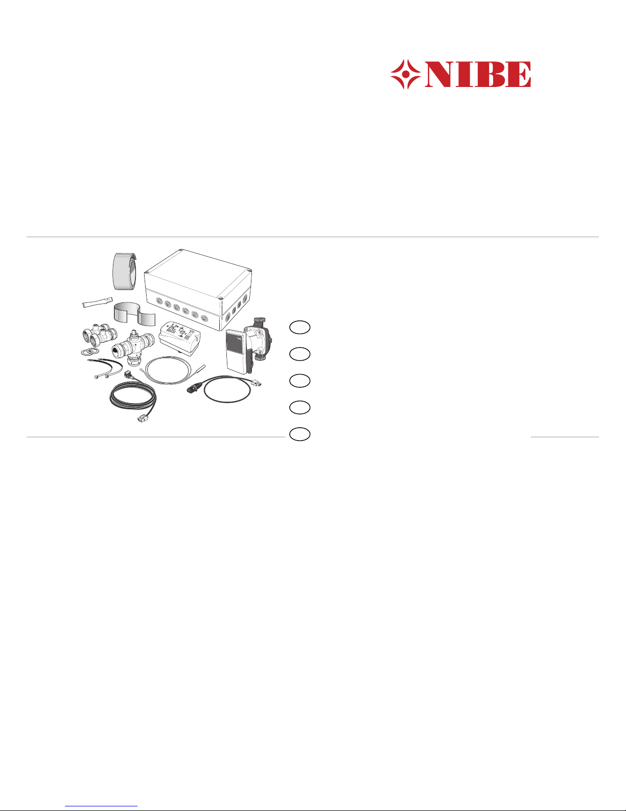
Innehåll
Laddpump1 st
PWM-kabel till cirkulationspump1 st
Kraftkabel till cirkulationspump1 st
Kulventiler med unionsmutter2 st
Planpackningar2 st
Buntband2 st
Ställdon växelventil1 st
Växelventil1 st
Apparatlåda1 st
Värmeledningspasta1 st
Aluminiumtejp1 st
Isoleringstejp1 st
Temperaturgivare1 st
3
Svenska, Installatörshandbok - POOL 310
SE

Komponentplacering apparatlåda (AA25)
LEK
AA5-X4
AA5-S2
AA5-X2 AA5-X9 X1
FA1
AA5-F1AA5
Elkomponenter
Automatsäkring, 10AFA1
Anslutningsplint, spänningsmatningX1
TillbehörskortAA5
Anslutningsplint, givare och extern bloc-
kering
AA5-X2
Anslutningsplint, kommunikationAA5-X4
Anslutningsplint, cirkulationspump, shunt
och hjälprelä
AA5-X9
DIP-switchAA5-S2
Finsäkring, T4AH250VAA5-F1
Beteckningar i komponentplacering enligt standard
IEC 81346.
4
SE

Röranslutning
Allmänt
När inomhusmodulen är dockad mot pool måste
laddkretsen förses med en yttre laddpump (GP12) då
det inte är möjligt att använda den interna laddpum-
pen. Den interna cirkulationspumpen upprätthåller
flödet i klimatsystemet under poolladdning.
Röranslutningar
1. Om inomhusmodulen redan är installerad och
vattenfylld så ska klimatsystemet och inomhusmo-
dulen tömmas på vatten. Se installatörshandboken
för inomhusmodulen för ytterligare instruktioner.
2. Rör till och från poolen kopplas in mellan värme-
pumpen och inomhusmodulen.
TIPS!
För att undvika onödiga värmeförluster bör
rören isoleras.
Cirkulationspump
Montera kulventilerna på cirkulationspumpen. Använd
medföljande planpackningar som tätning.
LEK
Kulventil
Planpackning
Cirkulationspump
Växelventil
Montera växelventilen (QN19) med port AB som inkom-
mande framledning från värmepumpen, port A mot
poolen och port B mot värmesystemet. Montera den
så att port AB är öppen mot port B när motorn är i vilo-
läge. Vid signal öppnar port AB mot port A.
B
A
AB
Temperaturgivare
Temperaturgivaren för pool (BT51) placeras på retur-
ledningen från poolen.
LEK
LEK
E
Temperaturgivaren monteras med buntband tillsam-
mans med värmeledningspasta och aluminiumtejp.
Därefter ska den isoleras med medföljande isolertejp.
OBS!
Givar- och kommunikationskablar får ej förläg-
gas i närheten av starkströmsledning.
5
SE

Systemprincip
Förklaring
PoolsystemCL11
ApparatlådaAA25
Temperaturgivare, poolBT51
Värmeväxlare, poolEP5
Cirkulationspump, poolGP9
Laddpump, poolGP12
SmutsfilterHQ4
Växelventil, poolQN19
VVM 310/VVM 320/VVM 325EB15
F2026/F2030/F2040EB101
SäkerhetsventilFL10
SmutsfilterHQ1
AvtappningsventilQM1
AvstängningsventilQM40, QM41
TrimventilRN10
Anslutning värmebärare, framXL1
Anslutning värmebärare, returXL2
Övrigt
ExpansionskärlCM1
Säkerhetsventil, klimatsystemFL2
Anslutning dockning, värmebärare inXL7
Anslutning dockning, värmebärare utXL8
Beteckningar enligt standard IEC 61346-2.
Dockning till pool
Uppvärmning av poolen prioriteras enligt valda inställningar i inomhusmodulen. Om poolgivaren (BT51) inte är
ansluten tillåts poolladdningen inte att starta.
Principschema VVM 310 och POOL 310
-FL2
-CM1
-EB15
-RN10
-EB101
XL2
XL1 -HQ1
-QM1
-QM41
-FL10
-QM40
-EB101
-GP9 -BT51 -HQ4
-EP5
-AA25
-CL11
-CL11-QN19
-CL11
-GP12
OBS! Detta är ett principschema. Verklig anläggning skall projekteras enligt gällande normer.
6
SE

Principschema VVM 320 och POOL 310
-GP9 -BT51 -HQ4
-EP5
-AA25
-CL11
-CL11
-QN19
-CL11
-GP12
POOL
-EB101
-FL10
-QM41
-QM40
-HQ1
-EB101
-XL1
-XL2
-XL8
-XL9
-EB15
OBS! Detta är ett principschema. Verklig anläggning skall projekteras enligt gällande normer.
Principschema VVM 325 och POOL 310
-EB15
-EB101
-FL10
-QM41
-QM40
-XL1
-XL2 -HQ1
-XL9
-XL8
-QM1
POOL
-CL11-QN19
-CL11-GP12
-GP9 -BT51 -HQ4
-EP5
-AA25
-CL11
OBS! Detta är ett principschema. Verklig anläggning skall projekteras enligt gällande normer.
7
SE

Elinkoppling
OBS!
All elektrisk inkoppling skall ske av behörig
elektriker.
Elektrisk installation och ledningsdragning
skall utföras enligt gällande bestämmelser.
Inomhusmodulen ska vara spänningslös vid
installation av POOL 310.
Elschema finns i slutet av denna installatörshandbok.
Anslutning av kommunikation
VVM 310/VVM 320/VVM 325
Detta tillbehör innehåller ett tillbehörskort (AA5) som
ska anslutas direkt till inomhusmodulen på ingångskor-
tet (plint AA3-X4).
Om flera tillbehör ska anslutas eller redan finns instal-
lerade måste nedanstående instruktion följas.
Det första tillbehörskortet ska anslutas direkt till inom-
husmodulens plint AA3-X4. De efterföljande korten
ansluts i serie med föregående kort.
Använd kabeltyp LiYY, EKKX eller likvärdig.
1
2
3
4
5
6
7
8
AA5-X4
15
A
B
GND
A
B
GND
A
B
GND
A
B
GND
A
B
GND
14
13
AA3-X4
1
2
3
4
5
6
7
8
AA5-X4
EB15
Tillbehörskort 1
Tillbehörskort 2
ON
12345678
-X9
-X2
24 20212223 1516171819 1011121314 56789 1
1
N
L
PE
PE
1
2
3
4
5
6
7
8
2
3
4
5
6
7
8
9
234
-X8
-X4
-X10
-X1
AA5-X4
ON
12345678
-X9
-X2
24 20212223 1516171819 1011121314 56789 1
1
N
L
PE
PE
1
2
3
4
5
6
7
8
2
3
4
5
6
7
8
9
234
-X8
-X4
-X10
-X1
AA5-X4
Inomhusmodul
AA3-X4
Anslutning av matning
Anslut spänningsmatningen till plint X1 enligt bild.
3
2
1N
230V 50Hz-X1
L
PE
Apparatlåda Externt
8
SE

ON
12345678
-X9
-X2
24 20212223 1516171819 1011121314 56789 1
1
N
L
PE
PE
1
2
3
4
5
6
7
8
2
3
4
5
6
7
8
9
234
-X8
-X4
-X10
-X1
AA5-X2 AA5-X9
AA5-X10
AA5-S2
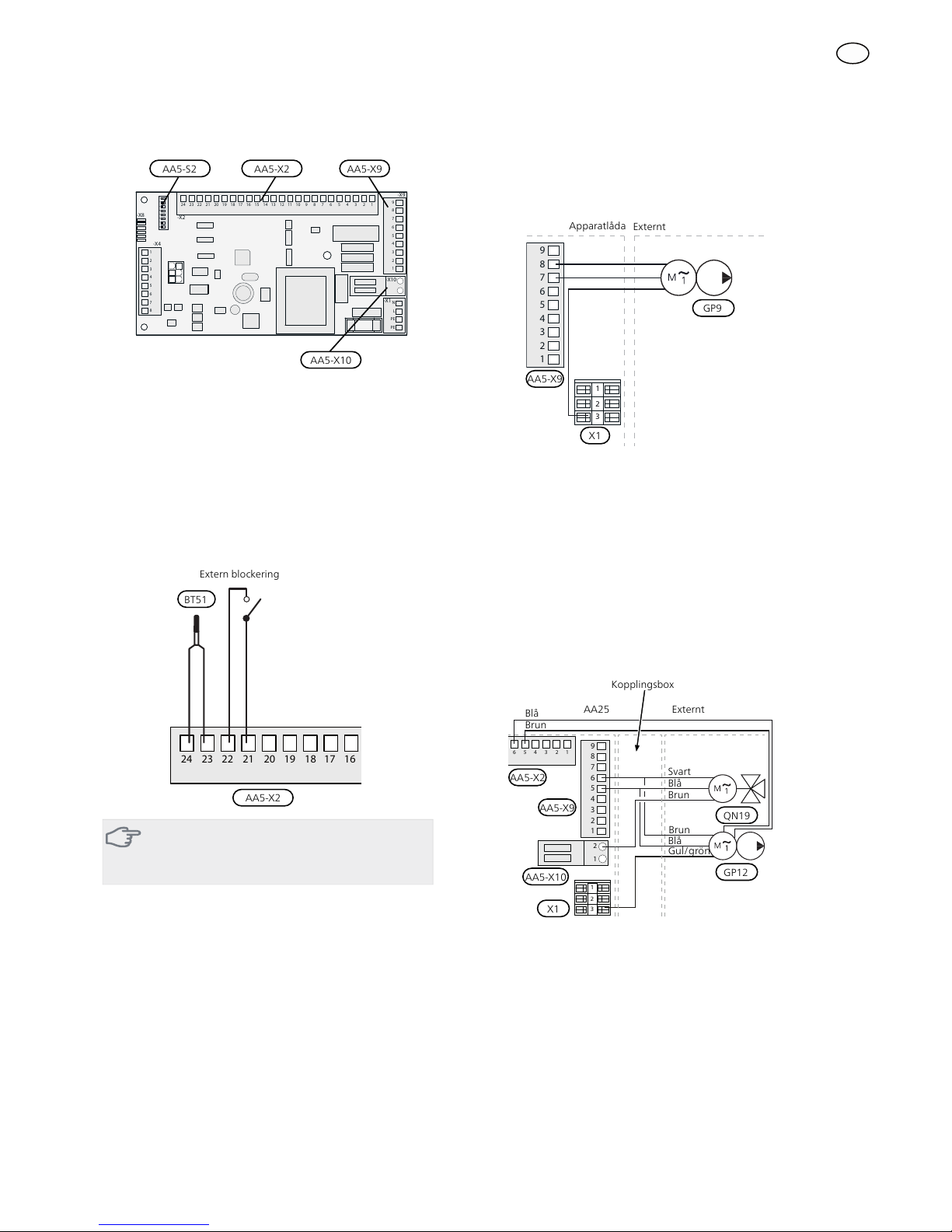
Anslutning av givare och extern blockering
Använd kabeltyp LiYY, EKKX eller likvärdig.
Poolgivare (BT51)
Anslut poolgivaren till AA5-X2:23-24.
Extern blockering (valfritt)
En kontakt kan anslutas till AA5-X2:21-22 för att kunna
blockera pooluppvärmningen. När kontakten sluts
blockeras pooluppvärmningen.
Extern blockering
AA5-X2
24 202122
23 1516171819 1314
BT51
TÄNK PÅ!
Reläutgångarna på tillbehörskortet får max
belastas med 2 A (230 V) totalt.
Anslutning av cirkulationspump (GP9)
Anslut cirkulationspumpen (GP9) till AA5-X9:8 (230 V),
AA5-X9:7 (N) och X1:3 (PE).
1
2
3
4
5
6
7
8
9
L
N
PE
3
2
1
1
2
3
4
5
6
7
8
9
3
2
1
Apparatlåda Externt
GP9
AA5-X9
X1
Anslutning av växelventilsmotor (QN19) och
laddpump, pool (GP12)
Anslut växelventilens motor (QN19) och laddpumpen
(GP12) till en extern kopplingsbox.
Anslut svart ledare från växelventilen samt brun ledare
från laddpumpen tillsammans i kopplingsboxen.
Anslut blå ledare från växelventilen samt blå ledare
från laddpumpen tillsammans i kopplingsboxen.
Anslut styrande kabel från kopplingsboxen till AA5-
X9:6 (signal), AA5-X9:5 (N), AA5-X10:2 (230 V) och
X1:3(PE). Anslut laddpumpens styrsignal till AA5-X2:5-6.
2
1
1
2
3
4
5
6
7
8
9
3456 12
3
2
1
Svart
Blå
Brun
AA25 Externt
AA5-X9 QN19
AA5-X10 GP12
X1
AA5-X2
Blå
Brun
Blå
Brun
Gul/grön
Kopplingsbox
9
SE

DIP-switch
DIP-switchen på tillbehörskortet ska ställas in enligt
nedan.
ON
1 2 3 4 5 6 7 8
AA5-S2
Aktivering av POOL 310
Programinställningen av POOL 310 kan göras via
startguiden eller direkt i menysystemet.
Startguiden
Startguiden visas vid första uppstart efter värmepumps-
installationen, men finns även i meny 5.7.
Menysystemet
Om du inte gör alla inställningar via startguiden eller
behöver ändra någon inställning kan du göra detta i
menysystemet.
Meny 5.2 - systeminställningar
Aktivering/avaktivering av tillbehör.
Meny 4.1.1 - pool
Aktivering av pooluppvärmning samt inställning av
start- och stopptemperatur.
Meny 5.1.11 - värmebärarpumpshastighet
Inställning av värmebärarpumpens hastighet.
TÄNK PÅ!
Se även Installatörshandboken för
inomhusmodulen.
10
SE

General
POOL 310 is an accessory that enables pool heating
with VVM 310/VVM 320/VVM 325. The indoor module
controls the reversing valve (QN19), the circulation
pump (GP9 and the charge pump (GP12).
Technical specifications
POOL 310
230V ~ 50 HzVoltage circulation pump
230V ~ 50 HzVoltage reversing valve
G1Connections pump
Ø 22, compression
ring
Connections reversing valve
7,5cwsvalue reversing valve
067247Part No.
Pump capacity diagram
0
10
20
30
40
50
60
70
80
0 200 400 600 800 1000 1200 1400 1600 1800 2000
Flöde (liter/timme)
Tillgängligt tryck [kPa]
Tillgängligt tryck cirkulationspump, GP1
Pressure
(kPa)
Flow (l/h)
Available pressure circulation pump, GP1
Contents
Charge pump1 x
PWM cable for circulation pump1 x
Power cable to circulation pump1 x
Ball valves with union nut2 x
Flat gaskets2 x
Cable ties2 x
Actuator reversing valve1 x
Shuttle valve1 x
Unit box1 x
Heating pipe paste1 x
Aluminium tape1 x
Insulation tape1 x
Temperature sensor1 x
11
English, Installer manual - POOL 310
GB

Component location unit box (AA25)
LEK
AA5-X4
AA5-S2
AA5-X2 AA5-X9 X1
FA1
AA5-F1AA5
Electrical components
Miniature circuit breaker, 10 AFA1
Terminal block, power supplyX1
Accessory cardAA5
Terminal block, sensors and external
blocking
AA5-X2
Terminal block, communicationAA5-X4
Terminal block, circulation pump, mixing
valve and auxiliary relay
AA5-X9
DIP switchAA5-S2
Fine wire fuse, T4AH250VAA5-F1
Designations in component locations according to
standard IEC 81346.
12
GB

Pipe connections
General
When the indoor module is docked to a pool, the
charge circuit must be supplied with an external charge
pump (GP12) as it is not possible to use the internal
charge pump. The internal circulation pump in main-
tains the flow in the climate system during pool char-
ging.
Pipe connections
1. If the indoor module has already been installed
and filled with water, the climate system and in-
door module must be drained of water. See the
Installer manual for the indoor module for further
instructions.
2. Pipes to and from the pool are connected between
the heat pump and the indoor module.
TIP
To prevent unnecessary heat losses insulate
the pipes.
Circulation pump
Install the ball valves on the circulation pump. Use the
flat gaskets supplied to seal.
LEK
Ball valve
Flat gasket
Circulation pump
Shuttle valve
Install the reversing valve (QN19) with port AB as incom-
ing flow line from the heat pump, port A towards the
pool and port B towards the heating system. Install it
so that port AB is open towards port B when the motor
is in standby mode. In the event of a signal port AB
opens towards port A.
B
A
AB
Temperature sensor
The pool temperature sensor (BT51) is located on the
return line from the pool.
LEK
LEK
E
Install the temperature sensor with cable ties with the
heat conducting paste and aluminium tape. Then insu-
late with supplied insulation tape.
NOTE
Sensor and communication cables must not
be placed near power cables.
13
GB

System diagram
Explanation
Pool systemCL11
Unit boxAA25
Temperature sensor, poolBT51
Heat exchanger, poolEP5
Circulation pump, poolGP9
Charge pump, poolGP12
Particle filterHQ4
Three way valve, poolQN19
VVM 310/VVM 320/VVM 325EB15
F2026/F2030/F2040EB101
Safety valveFL10
Particle filterHQ1
Tapping valveQM1
Shut-off valveQM40, QM41
Trim valveRN10
Connection heating medium, supplyXL1
Connection heating medium, returnXL2
Miscel-
laneous
Expansion vesselCM1
Safety valve, climate systemFL2
Connection docking, heating medium inXL7
Connection docking, heating medium
out
XL8
Designations according to standard IEC 61346-2.
Docking to pool
Heating of the pool is prioritised according to selected settings in the indoor module. If the pool sensor (BT51) is not
connected, pool charging is not permitted to start.
Outline diagram VVM 310 and POOL 310
-FL2
-CM1
-EB15
-RN10
-EB101
XL2
XL1 -HQ1
-QM1
-QM41
-FL10
-QM40
-EB101
-GP9 -BT51 -HQ4
-EP5
-AA25
-CL11
-CL11-QN19
-CL11
-GP12
Note! This is an outline diagram. Actual installations must be planned according to applicable standards.
14
GB

Outline diagram VVM 320 and POOL 310
-GP9 -BT51 -HQ4
-EP5
-AA25
-CL11
-CL11
-QN19
-CL11
-GP12
POOL
-EB101
-FL10
-QM41
-QM40
-HQ1
-EB101
-XL1
-XL2
-XL8
-XL9
-EB15
Note! This is an outline diagram. Actual installations must be planned according to applicable standards.
Outline diagram VVM 325 and POOL 310
-EB15
-EB101
-FL10
-QM41
-QM40
-XL1
-XL2 -HQ1
-XL9
-XL8
-QM1
POOL
-CL11-QN19
-CL11-GP12
-GP9 -BT51 -HQ4
-EP5
-AA25
-CL11
Note! This is an outline diagram. Actual installations must be planned according to applicable standards.
15
GB

Electrical connection
NOTE
All electrical connections must be carried out
by an authorised electrician.
Electrical installation and wiring must be car-
ried out in accordance with the stipulations in
force.
The indoor module must not be powered
when installing POOL 310.
The electrical circuit diagram is at the end of this In-
staller handbook.
Connecting communication
VVM 310/VVM 320/VVM 325
This accessory contains an accessory card (AA5) that
must be connected directly to the indoor module on
the input card (terminal block AA3-X4).
If several accessories are to be connected or are already
installed, the following instructions must be followed.
The first accessory card must be connected directly to
the indoor module's terminal block AA3-X4. The follow-
ing cards must be connected in series with the previous
card.
Use cable type LiYY, EKKX or similar.
1
2
3
4
5
6
7
8
AA5-X4
15
A
B
GND
A
B
GND
A
B
GND
A
B
GND
A
B
GND
14
13
AA3-X4
1
2
3
4
5
6
7
8
AA5-X4
EB15
Accessory card 1
Accessory card 2
ON
12345678
-X9
-X2
24 20212223 1516171819 1011121314 56789 1
1
N
L
PE
PE
1
2
3
4
5
6
7
8
2
3
4
5
6
7
8
9
234
-X8
-X4
-X10
-X1
AA5-X4
ON
12345678
-X9
-X2
24 20212223 1516171819 1011121314 56789 1
1
N
L
PE
PE
1
2
3
4
5
6
7
8
2
3
4
5
6
7
8
9
234
-X8
-X4
-X10
-X1
AA5-X4
Indoor module
AA3-X4
Connecting the supply
Connect the power supply to terminal block X1 as illus-
trated.
3
2
1N
230V 50Hz-X1
L
PE
Unit box External
16
GB

ON
12345678
-X9
-X2
24 20212223 1516171819 1011121314 56789 1
1
N
L
PE
PE
1
2
3
4
5
6
7
8
2
3
4
5
6
7
8
9
234
-X8
-X4
-X10
-X1
AA5-X2 AA5-X9
AA5-X10
AA5-S2
Connection of sensors and external blocking
Use cable type LiYY, EKKX or similar.
Pool sensor (BT51)
Connect the pool sensor to AA5-X2:23-24.
External blocking (optional)
A contact (NO) can be connected to AA5-X2:21-22 to
block pool heating. When the contact closes, pool
heating is blocked.
External blocking
AA5-X2
24 202122
23 1516171819 1314
BT51
Caution
The relay outputs on the accessory card can
have a max load of 2 A (230 V) in total.
Connection of the circulation pump (GP9)
Connect the circulation pump (GP9) to AA5-X9:8 (230
V), AA5-X9:7 (N) and X1:3 (PE).
1
2
3
4
5
6
7
8
9
L
N
PE
3
2
1
1
2
3
4
5
6
7
8
9
3
2
1
Unit box External
GP9
AA5-X9
X1
Connection of reversing valve motor (QN19)
and charge pump, pool (GP12)
Connect the reversing valve motor (QN19) and the
charge pump (GP12) to an external junction box.
Connect the black cable from the reversing valve and
the brown cable from the charge pump together in
the junction box.
Connect the blue cable from the reversing valve and
the blue cable from the charge pump together in the
junction box.
Connect the control cable from the junction box to
AA5-X9:6 (signal), AA5-X9:5 (N), AA5-X10:2 (230 V)
and X1:3(PE). Connect the charge pump control signal
to AA5-X2:5-6.
2
1
1
2
3
4
5
6
7
8
9
3456 12
3
2
1
Black
Blue
Brown
AA25 External
AA5-X9 QN19
AA5-X10 GP12
X1
AA5-X2
Blue
Brown
Blue
Brown
Yellow/green
Connection box
17
GB

DIP switch
The DIP switch on the accessory card must be set as
follows.
ON
1 2 3 4 5 6 7 8
AA5-S2
Activating POOL 310
Program setting of POOL 310 can be performed via the
start guide or directly in the menu system.
Start guide
The start guide appears upon first start-up after heat
pump installation, but is also found in menu 5.7.
Menu system
If you do not make all settings via the start guide or
need to change any of the settings, this can be done
in the menu system.
Menu 5.2 - system settings
Activating/deactivating of accessories.
Menu 4.1.1 - pool
Activating pool heating and setting start and stop
temperature.
Menu 5.1.11 - pump speed heating medium
Setting heating medium pump's speed.
Caution
Also see the Installer manual for
the indoor module.
18
GB

Allgemeines
Das Zubehör POOL 310 ermöglicht die Poolerwärmung
mit VVM 310/VVM 320/VVM 325. Das Innenmodul
steuert das Umschaltventil (QN19) sowie die Umwälz-
pumpe (GP9) und die Ladepumpe (GP12).
Technische Daten
POOL 310
230 V ~ 50 HzSpannung Umwälzpumpe
230 V ~ 50 HzSpannung Umschaltventil
G1Anschlüsse Pumpe
Ø 22, KlemmringAnschlüsse Umschaltventil
7,5kVs-Wert Umschaltventil
067247Art.nr.
Pumpenkapazitätsdiagramm
0
10
20
30
40
50
60
70
80
0 200 400 600 800 1000 1200 1400 1600 1800 2000
Flöde (liter/timme)
Tillgängligt tryck [kPa]
Tillgängligt tryck cirkulationspump, GP1
Druck
(kPa)
Durchfluss (l/h)
Verfügbarer Druck Umwälzpumpe,GP1
Inhalt
Ladepumpe1 St.
PWM-Kabel zur Umwälzpumpe1 St.
Stromversorgungskabel für Umwälzpumpe1 St.
Kugelventile mit Überwurfmutter2 St.
Flachdichtungen2 St.
Kabelbinder2 St.
Stellantrieb Umschaltventil1 St.
Wechselventil1 St.
Gerätegehäuse1 St.
Wärmeleitpaste1 St.
Aluminiumklebeband1 St.
Isolierband1 St.
Fühler1 St.
19
Deutsch, Installateurhandbuch - POOL 310
DE

Position der Komponenten im Gerätegehäu-
se (AA25)
LEK
AA5-X4
AA5-S2
AA5-X2 AA5-X9 X1
FA1
AA5-F1AA5
Elektrische Komponenten
Sicherungsautomat, 10AFA1
Anschlussklemme, SpannungsversorgungX1
ZubehörplatineAA5
Anschlussklemme für Fühler und extern
geschaltete Blockierung
AA5-X2
Anschlussklemme für Kommunikationslei-
tung
AA5-X4
Anschlussklemme für Umwälzpumpe,
Mischventil und Hilfsrelais
AA5-X9
DIP-SchalterAA5-S2
Feinsicherung, T4AH250VAA5-F1
Bezeichnungen der Komponentenpositionen gemäß
Standard IEC 81346.
20
DE
Other manuals for POOL 310
4
Table of contents
Languages:
Other Nibe Lighting Equipment manuals