manuals.online logo
Brands
  1. Home
  2. •
  3. Brands
  4. •
  5. Niles
  6. •
  7. Accessories
  8. •
  9. Niles MS-2 Troubleshooting guide

Niles MS-2 Troubleshooting guide

Type of Cable
The MS-2 connects to the IR main system unit
with 2-conductor shielded cable. We recom-
mend "data grade" cables made of two 28 gauge
(or larger) conductors surrounded by a foil
shield and a bare drain (ground) wire. Data
grade cable provides the capability for runs of
up to 500 feet to each sensor. Examples are
West Penn D291, Belden 8761 or Carol C2516.
Any non-data grade 22-16 gauge 2-conductor
3. Infrared Flashers transmit the infrared sig-
nals from the main system unit to your A/V com-
ponents. Niles manufactures both "flooding"
flashers (model IRC-1) and miniature "pin-point"
flashers (model IRC-2). Flashers are the "voice"
of an IR extender system.
In a typical system (Figure 1) the MS-2 remote
room sensors are placed in convenient locations
and are connected to a main system unit. The
main system unit is connected to power via its
12VDC power supply. In this example, the IRP-2
main system unit powers four IRC-2
MicroFlashers™which are attached to the front
panel sensor windows of four A/V components.
shielded cable, available at an electronic parts
store, will enable 150 foot runs to each sensor.
Data grade cable is available from Niles:
Part# FG00668.
MS-2 Mounting Location
Locating the MS-2 in the center of a room usual-
ly results in the most even IR receiving cover-
age, especially if the room is square shaped.
Rooms that are L-shaped or long and narrow
require more careful consideration. With these
types of rooms, installing the MS-2 closest to the
primary location of the user will ensure the best
performance.
The MS-2 is designed to surface-mount almost
anywhere. Convenient mounting locations for
the MS-2 include:
●On the front panel of a television set, facing
the viewer
● On the front surface of a wall, a cabinet, an
appliance, or a speaker grille
●Behind a speaker grille (speaker grilles typically
reduce the effective range of an MS-2 to 15 feet)
Receiving Range and Pickup Angle
The receiving range of the MS-2 will vary accord-
ing to the IR output strength of the remote control
being used. Remote strength varies among brands
by the number and size of the batteries used, and
how many IR emitters the remote has. For exam-
ple, remotes that operate on two small AAA bat-
teries and have only one IR emitter are generally
not as strong as remotes that use the larger AA
size batteries and have two emitters. Tests with
various manufacturers' remote controls have
shown that the operating range can vary from a
minimum of 18 feet to a maximum of about 30
feet. The IR pickup angle of the MS-2 is 60ooff-
axis (horizontal and vertical) at 18 feet.
Infrared signals travel essentially line-of-sight. They
will not pass through or around solid objects. Do
not rely on an IR signal being able to "bounce" off
a wall or reflective object to the MS-2.
When installing the MS-2 behind a speaker
grille expect to reduce the range of your remote
controls by half.
Avoiding Optical Interference
As with any type of IR sensor, avoid locating the
MS-2 where it will be exposed to direct sunlight.
The sun emits an enormous amount of IR ener-
gy, many times stronger than that of a hand-held
remote. Keep in mind that the less sunlight the
MS-2 receives, the better.
DO NOT mount the MS-2 outdoors. During
daylight hours, you will experience poor opera-
tion and/or interference.
Other potential sources of optical interference
include:
1.Bright reflections from windows, mirrors,
swimming pools, shiny floors or objects.
2. Placing the MS-2 within a few inches of a flu-
orescent light.
3. Placing the MS-2 within the same room as a
Neon sign.
Avoiding Electrical Interference
Avoid locating the MS-2 near any potential
sources of Electro-Magnetic Interference (EMI),
The most common sources are:
1. Some mounting positions on the front panel
of a television (particularly large direct view
sets ). If you are installing the MS-2 near a
television, test for an interference-free mount-
ing position (See page 9; Testing for EMI)
before permanently mounting it in place.
2. Light dimmers or variable speed controls for
ceiling fans. These controls emit more inter-
ference when turned down halfway. They
emit little or no interference when turned up
all the way (brightest or highest position).
3.Fluorescent Lights The electronic ballast
sometimes emits EMI.
4.Large appliances (air-conditioners, pumps,
motors, compressors; etc.)
5. AC line noise (noise brought into the system
via the wall outlet connected to the main sys-
tem unit)
Introduction
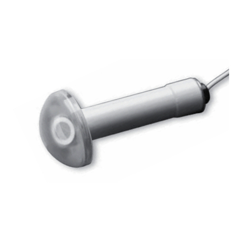
The MS-2 is a miniature IR sensor designed for
use with a Niles Infrared Extender System.
An IR (infrared) extender system enables you to
control your IR remote controlled A/V equip-
ment from a remote location. This allows you to
place your A/V components out of sight (behind
cabinet doors, in the rear of a room, or in a dif-
ferent room) and still conveniently control your
equipment.
The MS-2 is an IR Sensor. It is one of three
elements that make up an infrared exten-
der system:
1. IR Sensors receive IR commands from hand-
held remote controls and relay the commands
to the Main System Unit via a 2-conductor
shielded cable. Generally, sensors are placed so
that you can easily and naturally point your
remote control directly at them. Niles offers an
array of easily concealable sensors: wall-mount,
ceiling-mount, surface-mount and table-top. IR
sensors are the "eyes" of the system.
2. The Main System Unit provides a connec-
tion hub for the IR sensors and the IR flashers
and is generally located near the A/V compo-
nents. The main system unit’s level controls and
LED indicators enable you to calibrate and trou-
bleshoot an IR extender system. The main sys-
tem unit is the "heart" of an IR extender system.
Wiring MS-2 Sensors
From every IR Sensor location, you must "home-
run" a cable back to the main system unit.
"Home run" means an individual cable is con-
nected between each IR Sensor and the main
system unit. You should never daisy-chain (con-
nect in parallel) two or more IR Sensors to a sin-
gle input. (see Figure 2)
Combining MS-2 Sensors with Niles Keypads
There is only one exception to the "home run"
wiring rule is when you are placing both a key-
pad and a sensor (or two keypads) in one room.
Only in this case may you "daisy-chain" a single
cable. A cable is run between the keypad and
the sensor, then a single cable is run from either
the sensor or the keypad back to the main sys-
tem unit. See Figure 3.
12334567 OVER PLEASE
8
FEATURES AND BENEFITS
Quick and Easy Placement
The tiny housing (available in black or white)
and attractive appearance of the MS-2 give you
many placement possibilities. For instance, you
could place a black MS-2 immediately above
the sensor window of your television set. A
white MS-2 could be mounted to the front of a
white speaker grille. In either case the sensor
blends with its surroundings and mounts quickly
and easily with its self-adhesive mounting strip.
Sensible Operation
Every time you press a button on your remote
control, the bright green "flashback" LED confirms
that the MS-2 has received a command. If your
remote control’s batteries are weak and need to
be replaced, the absence of the "flashback" LED
will remind you.
Universal System
The MS-2 is compatible with virtually all brands
of A/V equipment. You can freely mix compo-
nents for the best performance.
Performance Guaranteed
100% tested, electronically for range, angle of
pickup, and brightness. The MS-2 has a limited
two year parts and labor warranty. The MS-2 is
proudly made in the U.S.A.
FEATURES AND BENEFITS
INTRODUCTION
INSTALLATION CONSIDERATIONS
MS-2 PARTS GUIDE
High Sensitivity
Photo Diode
Green
“Flashback”LED
Adhesive-
Backed
Strip for
Mounting
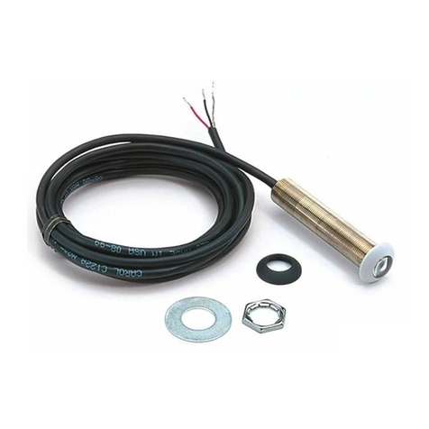
6 Feet of 2-Conductor
Shielded 28 Gauge
Connecting Wire
+
12
V
FLASHERS
VAR FULL
SENSOR
IN SENSOR
IN IRDATA
OUT
G
N
D
D
A
T
A
+
12
V
G
N
D
D
A
T
A
G
N
D
D
A
T
A
+
-
+
-
NILES
IRP-2
IR
FLASHERLEVEL
+12VDC
P
O
W
E
R
MS-2 IR Sensor in a remote location.
IR Main System Unit.
DO NOT USE UNSHIELDED CABLE WITH THE MS-2
Figure 1
“TECH TIP”
Wire size is
expressed by its
AWG (American Wire
Gauge) number. The
lower the number,
the larger the wire,
i.e. twelve AWG is
physically larger than
fourteen AWG.
@@@@@@@@e?
@@@@@@@@e?
@@h?
@@h?
@@h?
@@h?
@@h?
@@h?
@@@@@@@@e?@@@@@@@@?e@@@@@@@@e?@@@@@@@@?e@@@@@@@@e?@@@@@@@@?e@@@@@@@@e?@@@@@@@@?e@@@@@@@@e?@@@@@@@@?e@@@@@@@@e?@@@@@@@@?e@@@@@@@@e?@@@@@@@@?e@@@@@@@@e?@@@@@@@@?e@@@@@@@@e?@@@@@@@@?e@@@@@@@@e?@@@@@@@@?e@@@@@@@@e?@@@@@@@@?e@@@@@@@@e?
@@@@@@@@
@@@@@@@@
@@
@@
@@
@@
@@
@@
@@
@@
@@
@@
@@
@@
@@
@@
@@
@@
@@
@@
@@
@@
@@
@@
@@
@@
@@
@@
@@
@@
@@
@@
@@
@@
@@
@@
@@
@@
@@
@@
@@
@@
@@
@@
@@
@@
@@
@@
@@
@@
@@
@@
@@
@@
@@
@@
@@
@@
@@
@@
@@
@@
@@
@@
@@
@@
@@
@@
@@
@@
@@
@@
@@
@@
@@
@@
@@
@@
@@
@@
@@
@@
@@
@@
@@
@@
@@
@@
?@@
?@@
?@@
?@@
?@@
?@@
?@@@@@@@@
?@@@@@@@@
?@@@@@@@@?e@@@@@@@@e?@@@@@@@@?e@@@@@@@@e?@@@@@@@@?e@@@@@@@@e?@@@@@@@@?e@@@@@@@@e?@@@@@@@@?e@@@@@@@@e?@@@@@@@@?e@@@@@@@@e?@@@@@@@@?e@@@@@@@@e?@@@@@@@@?e@@@@@@@@e?@@@@@@@@?e@@@@@@@@e?@@@@@@@@?e@@@@@@@@e?@@@@@@@@?e@@@@@@@@e?@@@@@@@@
@@g
@@g
@@g
@@g
@@g
@@g
@@@@@@@@
@@@@@@@@
@@
@@
@@
@@
@@
@@
@@
@@
@@
@@
@@
@@
@@
@@
@@
@@
@@
@@
@@
@@
@@
@@
@@
@@
@@
@@
@@
@@
@@
@@
@@
@@
@@
@@
@@
@@
@@
@@
@@
@@
@@
@@
@@
@@
@@
@@
@@
@@
@@
@@
@@
@@
@@
@@
@@
@@
@@
@@
@@
@@
@@
@@
@@
@@
@@
@@
@@
@@
@@
@@
@@
@@
@@
@@
@@
@@
@@
@@
@@
@@
Room 1
@@@@@@@@e?
@@@@@@@@e?
@@h?
@@h?
@@h?
@@h?
@@h?
@@h?
@@@@@@@@e?@@@@@@@@?e@@@@@@@@e?@@@@@@@@?e@@@@@@@@e?@@@@@@@@?e@@@@@@@@e?@@@@@@@@?e@@@@@@@@e?@@@@@@@@?e@@@@@@@@e?@@@@@@@@?e
@@@@@@@@
@@@@@@@@
@@
@@
@@
@@
@@
@@
@@
@@
@@
@@
@@
@@
@@
@@
@@
@@
@@
@@
@@
@@
@@
@@
@@
@@
@@
@@
@@
@@
@@
@@
@@
@@
@@
@@
@@
@@
@@
@@
@@
@@
@@
@@
@@
@@
@@
@@
@@
@@
@@
@@
@@
@@
@@
@@
@@
@@
@@
@@
@@
@@
@@
@@
@@
@@
@@
@@
@@
@@
@@
@@
?@@
?@@
?@@
?@@
?@@
?@@
?@@@@@@@@
?@@@@@@@@
?@@@@@@@@?e@@@@@@@@e?@@@@@@@@?e@@@@@@@@e?@@@@@@@@?e@@@@@@@@e?@@@@@@@@?e@@@@@@@@e?@@@@@@@@?e@@@@@@@@e?@@@@@@@@?e@@@@@@@@
@@g
@@g
@@g
@@g
@@g
@@g
@@@@@@@@
@@@@@@@@
@@
@@
@@
@@
@@
@@
@@
@@
@@
@@
@@
@@
@@
@@
@@
@@
@@
@@
@@
@@
@@
@@
@@
@@
@@
@@
@@
@@
@@
@@
@@
@@
@@
@@
@@
@@
@@
@@
@@
@@
@@
@@
@@
@@
@@
@@
@@
@@
@@
@@
@@
@@
@@
@@
@@
@@
@@
@@
@@
@@
@@
@@
@@
@@
Room 2
MS-2
MS-2 / Keypad
IR Main System Unit
IR Main System Unit
+
12
V
FLASHERS
VAR FULL
SENSOR
IN SENSOR
IN IRDATA
OUT
G
N
D
D
A
T
A
+
12
V
G
N
D
D
A
T
A
G
N
D
D
A
T
A
+
-
+
-
NILES
IRP-2
IR
FLASHERLEVEL
+12VDC
P
O
W
E
R
+
12
V
FLASHERS
VAR FULL
SENSOR
IN SENSOR
IN IRDATA
OUT
G
N
D
D
A
T
A
+
12
V
G
N
D
D
A
T
A
G
N
D
D
A
T
A
+
-
+
-
NILES
IRP-2
IR
FLASHERLEVEL
+12VDC
P
O
W
E
R
Figure 3 : An IR Sensor cable is “daisy-chained” from
an MS-2 to a Keypad and then back to the Main
System Unit. Never “daisy-chain” two IR sensors.
@@@@@@@@e?
@@@@@@@@e?
@@h?
@@h?
@@h?
@@h?
@@h?
@@h?
@@@@@@@@e?@@@@@@@@?e@@@@@@@@e?@@@@@@@@?e@@@@@@@@e?@@@@@@@@?e@@@@@@@@e?@@@@@@@@?e@@@@@@@@e?@@@@@@@@?e@@@@@@@@e?@@@@@@@@?e@@@@@@@@e?@@@@@@@@?e@@@@@@@@e?@@@@@@@@?e@@@@@@@@e?@@@@@@@@?e@@@@@@@@e?@@@@@@@@?e@@@@@@@@e?@@@@@@@@?e@@@@@@@@e?
@@@@@@@@
@@@@@@@@
@@
@@
@@
@@
@@
@@
@@
@@
@@
@@
@@
@@
@@
@@
@@
@@
@@
@@
@@
@@
@@
@@
@@
@@
@@
@@
@@
@@
@@
@@
@@
@@
@@
@@
@@
@@
@@
@@
@@
@@
@@
@@
@@
@@
@@
@@
@@
@@
@@
@@
@@
@@
@@
@@
@@
@@
@@
@@
@@
@@
@@
@@
@@
@@
@@
@@
@@
@@
@@
@@
@@
@@
@@
@@
@@
@@
@@
@@
@@
@@
@@
@@
@@
@@
@@
@@
?@@
?@@
?@@
?@@
?@@
?@@
?@@@@@@@@
?@@@@@@@@
?@@@@@@@@?e@@@@@@@@e?@@@@@@@@?e@@@@@@@@e?@@@@@@@@?e@@@@@@@@e?@@@@@@@@?e@@@@@@@@e?@@@@@@@@?e@@@@@@@@e?@@@@@@@@?e@@@@@@@@e?@@@@@@@@?e@@@@@@@@e?@@@@@@@@?e@@@@@@@@e?@@@@@@@@?e@@@@@@@@e?@@@@@@@@?e@@@@@@@@e?@@@@@@@@?e@@@@@@@@e?@@@@@@@@
@@g
@@g
@@g
@@g
@@g
@@g
@@@@@@@@
@@@@@@@@
@@
@@
@@
@@
@@
@@
@@
@@
@@
@@
@@
@@
@@
@@
@@
@@
@@
@@
@@
@@
@@
@@
@@
@@
@@
@@
@@
@@
@@
@@
@@
@@
@@
@@
@@
@@
@@
@@
@@
@@
@@
@@
@@
@@
@@
@@
@@
@@
@@
@@
@@
@@
@@
@@
@@
@@
@@
@@
@@
@@
@@
@@
@@
@@
@@
@@
@@
@@
@@
@@
@@
@@
@@
@@
@@
@@
@@
@@
@@
@@
Room 2
Figure 2 : Home run the Sensor cable from each
sensor to the IRP-2.
Other Problems
A full trouble-shooting guide can be found in
the manual of your IR Main System Unit.
IR System
Compatible with virtually all brands of remotes
using carrier frequencies between 18 kHz and
100 kHz.
IR Receiving Range
Varies depending on remote strength; typically
18-30 feet.
IR Receiving Angle
60ooff-axis (horizontal and vertical) at 18 feet.
Mounting
Surface-mount. Self-adhesive mounting strip
included.
Wiring Requirements
Individual home-runs of 2-conductor shielded
cable, West Penn D291 or equivalent.
Unit Dimensions
Overall Unit: 2" Long x 1/2" Wide x 1/4" High.
If the MS-2 does not work, and the LED “flick-
ers” or remains solidly lit: Cover up the Sensor
with a piece of cardboard (your hand will actu-
ally create electromagnetic interference under
some conditions). Observe the IR test LED.
IR Test LED Off: Optical Interference
IR Test LED On or Flickering: Electromagnetic
Interference
Optical Interference
Identify the source of the interference. The most
common sources of optical interference are listed
in the Installation Considerations section on page
7. Either re-orient the sensor or move the source
of interference. If this is not possible, consider
exchanging your MS-2 for an IRR-4D, TIR-1 or a
CMS-3 ceiling sensor. These three sensors have
AGC circuits which serve as automatic filters.
EMI (Electromagnetic Interference)
Identify the source of the interference. The
most common sources of electromagnetic
interference are listed in the Installation
Considerations section on page 8. To elimi-
nate EMI try the following methods:
1.Move the sensor or the sensor cable away
from the EMI source or move the source of
the EMI away from the sensor or the cable.
2. Shield the sensor with a metal J-Box.
3. Connect the Sensor’s GND terminal to true
earth ground (if this isn’t feasible use the main
system unit’s GND terminal).
Troubleshooting
Eliminating Optical Feedback
In some installations, two conditions combine to
create an optical feedback loop. Symptoms can
include: poor range, intermittent operation or no
operation.
The conditions which sometimes combine to
create a feedback loop are:
1. Both a sensor and a flasher are located within
the same room.
2. There is some low-level noise or interference
on your system.
You can eliminate optical feedback by replacing
any IRC-1 "flooding flashers" with IRC-2 "pin-
point" MicroFlashers™and covering all flashers
with the supplied IR blocking covers.
Identifying the Type of Interference
The "flash-back" LED on the front of the MS-2 is
a useful trouble-shooting aid.
The LED should light only when a remote com-
mand is being received. However, if the LED on
the MS-2 "flickers" dimly, and the MS-2 func-
tions normally, there is no cause for concern.
If the MS-2 does not work, and the LED does
not light at all: Test the remote control(s) by
operating the A/V equipment directly. Replace
the batteries if needed. Double check the cable
connections on all MS-2's Main System Unit
and on the IR Main System Unit. Consult your
IR Main System Unit’s manual for more detail.
Connecting to the Main System Unit
Strip 1/4" of insulation from the end of each
wire. Tightly twist the end of each wire until
there are no frayed ends. Insert the end of each
wire into the appropriate hole on the main sys-
tem unit's connector block. Secure the wiring to
the connector by tightening the small connector
screws. Double-check all con-
nections. This manual contains
instructions for the MS-2 only. For
specific information on the
adjustment of your Niles Infrared
system, please refer to the instruc-
tion manual included with your
Niles IR Main System Unit.
Operation
Operation of the MS-2 is straightforward. Simply
aim your hand-held remote at the MS-2. Your IR
command is instantly repeated to your A/V equip-
ment. A green "flash-back" LED on the MS-2 visu-
ally confirms the receipt of an IR signal.
high level of electrical interference. Move the
MS-2 housing to a location where the LED does
not light.
Extending the Cable
Once the cable is in place, label the cable ends for
future reference. The MS-2 is supplied with 6' of
pre-stripped IR cable. The IR cable may be length-
ened as needed. The IR cable may be lengthened
by splicing it to a recommended IR cable (See
page 5, Installation Considerations—Type of
Cable). You may splice the MS-2 cable to another
cable by soldering or crimping the connections.
Make sure that you maintain proper polarity and
correct connections through the splice.
After you’ve extended the wire strip 1/4” of insu-
lation from the end of each wire. Tightly twist
the end of each conductor until there are no
frayed ends.
Concealing the Wire
If you are installing the wire into an existing
wall, take time to consider any possible obstruc-
tions which may be hidden inside the wall, such
as wood and metal studs; electrical, telephone
or other types of wiring; plumbing; conduit; old
wall safes; etc.
If the MS-2 cable needs to pass through any
cabinetry (or other obstruction) drill a 1/8" hole
where the cable will run.
Installation
Determine a mounting location for the MS-2. If
there is a potential source of EMI near the pro-
posed mounting location (e.g nearby or on a
television set) you must test to find the best
(interference-free) position before mounting the
MS-2 in place.
Clean and dry the mounting surface. Peel off the
protective layer on the self-adhesive pad and
firmly affix the MS-2 to the mounting surface.
Testing for EMI ( Electrical Interference)
1. Turn on the device. If it is a wall mounted
light dimmer turn the dimmer knob to the
halfway position.
2. Connect the MS-2 to a main system unit and
plug in the 12VDC power supply.
3. Place the MS-2 in the proposed mounting loca-
tion and observe the green "Flashback" LED.
3. If it flickers or lights constantly. This indicates a
910 12 13 1411
www.nilesaudio.com
Niles Audio Corporation
12331 S.W. 130 Street Miami, Florida 33186
Tel: (305) 238-4373 Fax: (305) 238-0185
© 1999 Niles Audio Corporation. All rights reserved. Because Niles
continually strives to improve the quality of its products, Niles
reserves the right to change product specifications without notice.
Niles, the Niles logo and Blending High Fidelity and Architecture are
registered trademarks of Niles Audio Corporation. MicroFlasher
is a trademark of Niles Audio Corporation. Printed in USA
2/99 DS00143A
MS-2
MS-2
Miniature Surface-Mount
IR Sensor
INSTALLATION & OPERATION GUIDE
BLENDING HIGH FIDELITY
AND ARCHITECTURE®
INSTALLATION
OPERATION
TROUBLE-SHOOTING
SPECIFICATIONS
SENSOR IN
D
A
T
A
G
N
D
+
12
V
Bare
Red Black
CONNECTIONS
• Red conductor is positive (12VDC +)
• Braid (shield) is ground (GND)
• Black conductor is data
NOTE: The color code shown above is for
West Penn D291 IR cable. Actual color
code of recommended cables may vary.
TOOLS REQUIRED
• 1/8" Standard slotted screwdriver
• Wire stripper
• Crimping tool with crimp rings or
Soldering gun with solder
• Heat shrink tubing or electrical tape.

Other Niles Accessories manuals

Niles WS100R User manual

Niles

Niles WS100R User manual

Niles Voltage Activated AC Outlet AC-3 User manual

Niles

Niles Voltage Activated AC Outlet AC-3 User manual

Niles WS120 User manual

Niles

Niles WS120 User manual

Niles CS120 Original operating instructions

Niles

Niles CS120 Original operating instructions

Niles 525 User manual

Niles

Niles 525 User manual

Niles CS120 Original operating instructions

Niles

Niles CS120 Original operating instructions

Niles IE6 User manual

Niles

Niles IE6 User manual

Niles IE5 User manual

Niles

Niles IE5 User manual

Niles DS6 Series Bracket User manual

Niles

Niles DS6 Series Bracket User manual

Niles SRK-1W User manual

Niles

Niles SRK-1W User manual

Niles IRR-4S Troubleshooting guide

Niles

Niles IRR-4S Troubleshooting guide

Niles CM75 Series Bracket User manual

Niles

Niles CM75 Series Bracket User manual

Niles Component Commander User manual

Niles

Niles Component Commander User manual

Niles TS120 User manual

Niles

Niles TS120 User manual

Niles C5-DA User manual

Niles

Niles C5-DA User manual

Niles MS-1 Troubleshooting guide

Niles

Niles MS-1 Troubleshooting guide

Niles SRK-4W User manual

Niles

Niles SRK-4W User manual

Niles DBI-1 User manual

Niles

Niles DBI-1 User manual

Niles MSU250 Guide

Niles

Niles MSU250 Guide

Niles IntelliPad TSP-1 User manual

Niles

Niles IntelliPad TSP-1 User manual

Niles C5-A2 User manual

Niles

Niles C5-A2 User manual

Niles MSU250 User manual

Niles

Niles MSU250 User manual

Niles RCA3 User manual

Niles

Niles RCA3 User manual

Niles CAT-5 User manual

Niles

Niles CAT-5 User manual

Popular Accessories manuals by other brands

Philips CRP367 brochure

Philips

Philips CRP367 brochure

2gig Technologies PASSIVE INFRARED MOTION DETECTOR Install instructions

2gig Technologies

2gig Technologies PASSIVE INFRARED MOTION DETECTOR Install instructions

Pepperl+Fuchs NJ1,5-6,5-15-N-Y180094 instruction manual

Pepperl+Fuchs

Pepperl+Fuchs NJ1,5-6,5-15-N-Y180094 instruction manual

SolarFocus Technology Power+ user guide

SolarFocus Technology

SolarFocus Technology Power+ user guide

Saje Aroma Roam manual

Saje

Saje Aroma Roam manual

Contrinex DGI-A Series operating manual

Contrinex

Contrinex DGI-A Series operating manual

JETStream HOME GYM MG-510 owner's manual

JETStream

JETStream HOME GYM MG-510 owner's manual

Panasonic GX-M Series instruction manual

Panasonic

Panasonic GX-M Series instruction manual

Hama 00047771 operating instructions

Hama

Hama 00047771 operating instructions

Stern Csaba user manual

Stern

Stern Csaba user manual

weinor PergoTex Type A Maintenance instructions and directions for use

weinor

weinor PergoTex Type A Maintenance instructions and directions for use

Krüger & Matz KM0901 owner's manual

Krüger & Matz

Krüger & Matz KM0901 owner's manual

Waldbeck Power Rock manual

Waldbeck

Waldbeck Power Rock manual

e-Domotica EM6581 manual

e-Domotica

e-Domotica EM6581 manual

inventum HN131MW instruction manual

inventum

inventum HN131MW instruction manual

Pyxis ST-774 user manual

Pyxis

Pyxis ST-774 user manual

Vega FIBERTRAC 32 quick start guide

Vega

Vega FIBERTRAC 32 quick start guide

PHYWE Cobra SMARTsense CO2 operating instructions

PHYWE

PHYWE Cobra SMARTsense CO2 operating instructions

manuals.online logo
manuals.online logoBrands
  • About & Mission
  • Contact us
  • Privacy Policy
  • Terms and Conditions

Copyright 2025 Manuals.Online. All Rights Reserved.