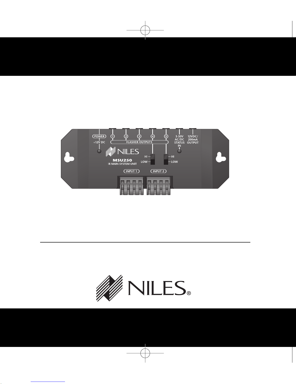
Niles MSU250 Guide
Other Niles Accessories manuals

Niles
Niles Flush-Mount IR MicroSensor MS110 Operating instructions

Niles
Niles CE 70 User manual

Niles
Niles CM75 Series Bracket User manual

Niles
Niles WS120 User manual

Niles
Niles MS-360 Troubleshooting guide

Niles
Niles WS100R User manual

Niles
Niles CE-DS6 User manual

Niles
Niles SRK-1W User manual

Niles
Niles C1 Installation guide

Niles
Niles CS120 Original operating instructions

Niles
Niles CE-DS8 User manual

Niles
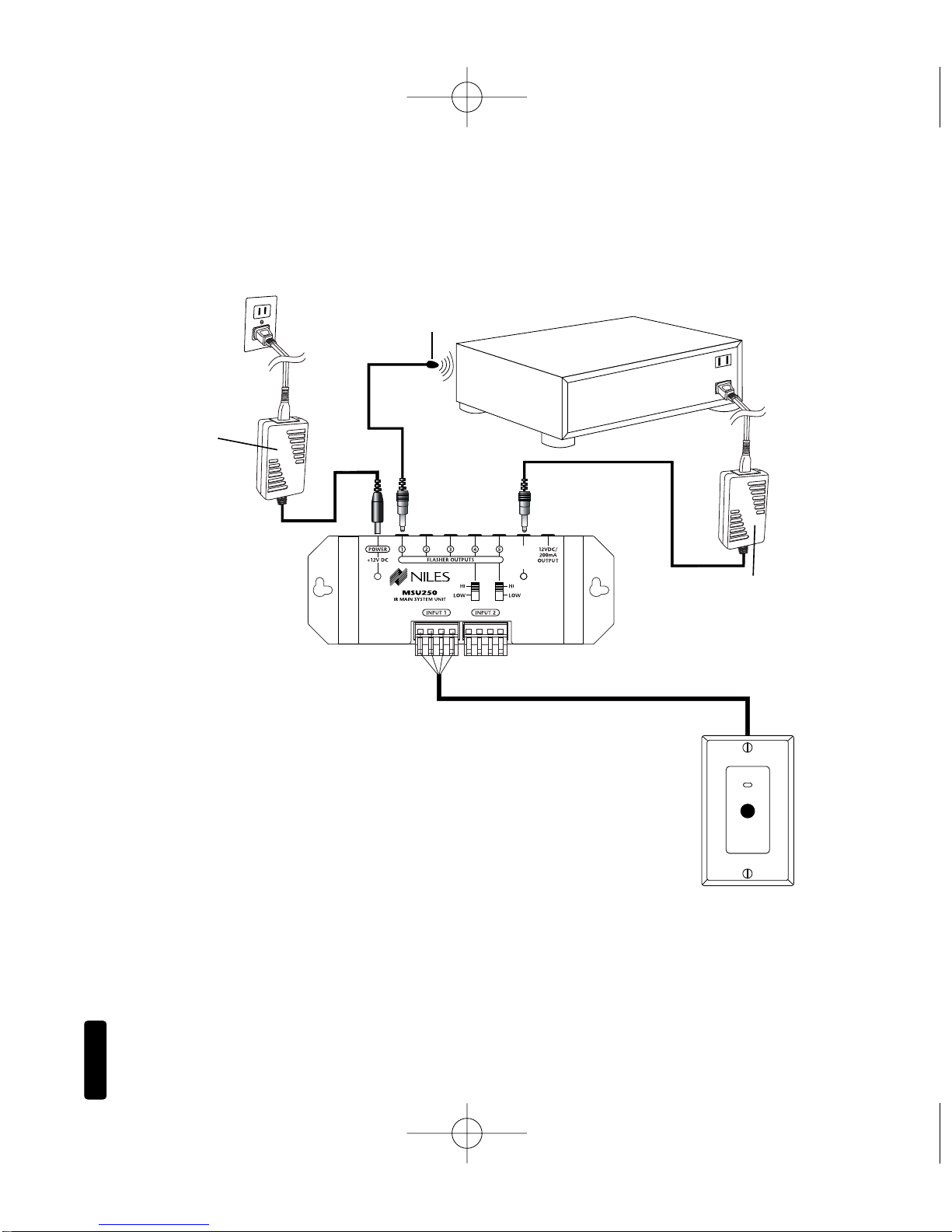
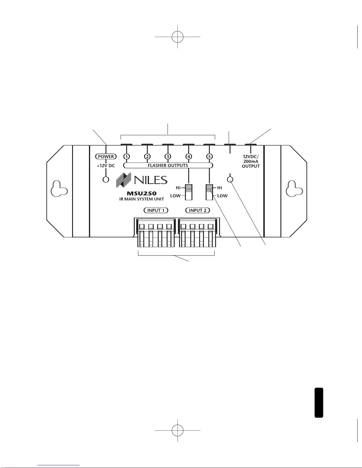
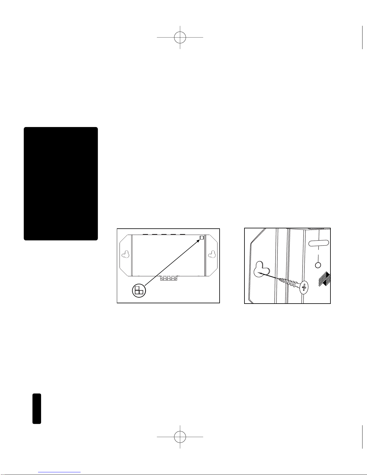
Niles MSU250 User manual

Niles
Niles MSU140 User manual

Niles
Niles MS-1 Troubleshooting guide

Niles
Niles DBI-1 Original operating instructions

Niles
Niles TS120 User manual

Niles
Niles CS120 Original operating instructions

Niles
Niles CM6 Series Bracket User manual

Niles
Niles IE5 User manual

Niles
Niles MSU140 Troubleshooting guide