INSTALLATION CONSIDERATIONS
IMPORTANT: REFER INSTALLATION TO A PROFES-
SIONAL CUSTOM INSTALLER IF YOU ARE UNFAMIL-
IAR WITH ANY OF THE FOLLOWING PROCEDURES.
TOOLS REQUIRED
• 1/8” Standard Slotted Screwdriver
• 1/4” Standard Slotted Screwdriver
• Wire Stripper
Type of Cable
The CS120 connects to the Niles Infrared main sys-
tems unit or IRH610 sensor expansion hub with an
individual home run of CAT-5 cable. When running
wires inside walls, most states and municipalities
in the U.S. specify that you must use a special type
of wire. Usually, the requirement is that the wire
has a specific “CL” fire rating, such as “CL-2” or
“CL-3”. Consult your Niles dealer, building contrac-
tor, or local building and inspection department if
unsure about which type of wire is best for your
application.
CS120 Mounting Location
The CS120 is designed to be ceiling mounted in
a direct line of sight location within the operating
range of the remote control.
Receiving Range and Pickup Angle
The receiving range of the CS120 will vary accord-
ing to the IR output strength of the remote control
being used. Remote strength varies among brands
depending on the number and size of batteries
used, and how many IR emitters the remote has.
For example, remotes that operate on two small
AAA batteries and have only one IR emitter are
generally not as strong as remotes that use the
larger AA size batteries and have two emitters.
Tests with various manufacturers’ remote controls
have shown that the operating range can vary from
a minimum of 20’ to a maximum of about 35’.
Infrared signals travel essentially line-of-sight. They
will not pass through or around solid objects. Do not
rely on an IR signal being able to “bounce” off a wall
or object to the CS120. The IR pickup angle of the
CS120 is 30° off-axis (horizontal and vertical) at 25’.
Avoiding Interference
CS120 is designed to work in most applications
including with LCD and plasma displays and in
areas where CFL lighting and indirect sunlight are
present. You should avoid locating the CS120 near
potential sources of electrical or optical noise, such
as light dimmers or low-voltage lights.
Avoiding Optical Feedback
If installing the CS120 in the same room as an IR
flasher, it is possible for the flasher’s IR output to
be picked-up by the CS120. This effect, known
as an optical feedback loop, can cause erratic
operation. Optical feedback is similar to acoustical
feedback: the howling or whistling sound heard in
a P.A. system when the microphone is too close to
the speaker.
5 63 41 2 7 8
INTRODUCTION
The CS120 is a ceiling mounted IR sensor designed
for use with the Niles infrared extender systems.
Installed in a remote room location, the CS120
receives the IR commands transmitted from your
existing hand-held remotes in that room. The
commands are carried via a category 5 cable to
your A/V equipment in another room, and instantly
“repeated”.
The CS120 is compatible with all current Niles
infrared systems. It may be used along with, or as
an alternative to, the Niles TS120, MS120, MS220,
WS120R and MVC100IR sensors or the IntelliPad®.
The CS120 is just one part of the three building
blocks necessary to complete a Niles IR repeating
system
• IR Main System Unit—Models MSU140, MSU250,
MSU480 and MSU440Z
• IR Sensors/Keypads—Models WS120R, TS120,
MS120, MS220, CS120 and the IntelliPad
• IR Flashers—Models MF1, MF2, MF1VF,
MF2VF and the IRB1
An IR sensor expansion hub, Model IRH610, is
available to provide additional sensor inputs to
your system.
FEATURES & BENEFITS
The CS120 offers a number of improvements over
other miniature IR sensors.
• Wideband High-Fidelity Design enables operation
with virtually any brand of equipment
• Patent Pending Universal Noise Suppression en-
ables operation in virtually any environment: near
plasma and LCD displays, compact fluorescent
lights, and indirect sunlight
• Excellent IR receiving range — 20’ to 35’ of
remote control range (depending upon the
strength of your handheld remote)
• Factory tested for pickup range and angle
• Small size of only 1/2” diameter by 2-7/8”
long—fits almost anywhere
• 10’ of connecting wire included
• Printed circuit board design uses surface mount
technology, assuring high reliability
• Ideal for both home and commercial installations
• Each CS120 includes a transparent cover
• Two year parts and labor limited warranty
To avoid optical feedback:
1. Re-position the flasher(s) and/or the sensor
2. Use Niles an MF1 or MF2 Microflasher and cover
them with the supplied IR blockers
Using the CS120 with the Niles MultiZone
keypads with an IR connection
The CS120 is fully compatible with Niles MultiZone
keypads with an IR connection,follow the wiring
instructions in Figure 5. For specific information
see your Niles MultiZone keypad manual.
INSTALLATION
If you are installing the CS120 into an existing
ceiling, take time to consider any possible obstruc-
tions which may be hidden, such as wood or metal
studs, electrical, telephone or other types of wiring,
plumbing, AC or heating conduits, etc.
1. Determine a mounting location for the CS120
2. Drill a 11/16" hole where the CS120 will be
mounted
3. Run the CS120’s IR cable. Label the cable for
future reference ( Figure 2). The CS120 is sup-
plied with 10’ of pre-stripped IR cable. The IR ca-
ble may be shortened or lengthened as needed.
If you want to make the CS120’s cable shorter,
use a pair of wire cutters to cut the cable to the
desired length. The IR cable may be lengthened
by splicing it to a recommended IR cable (See
Installation Considerations—Type of Cable). You
may splice the CS120 cable to another cable by
soldering or crimping the connections.
4. Fasten sensor to ceiling with supplied screws
(Figure 3)
5. Connect the CS120 cable to the main system
unit ( Figure 1). Strip 1/4” of insulation from the
end of each wire. Tightly twist the end of each
wire until there are no frayed ends. Insert each
wire into the appropriate hole on the removable
connector plug, and snap the locking tab down.
To help you, the connector plug is keyed. Insert the
smooth side of the connector plug into the smooth
side of the socket. Don’t force the scalloped side
of the connector plug into the smooth side of the
socket. Refer to the main system main system unit
manual for specific installation instrutions.
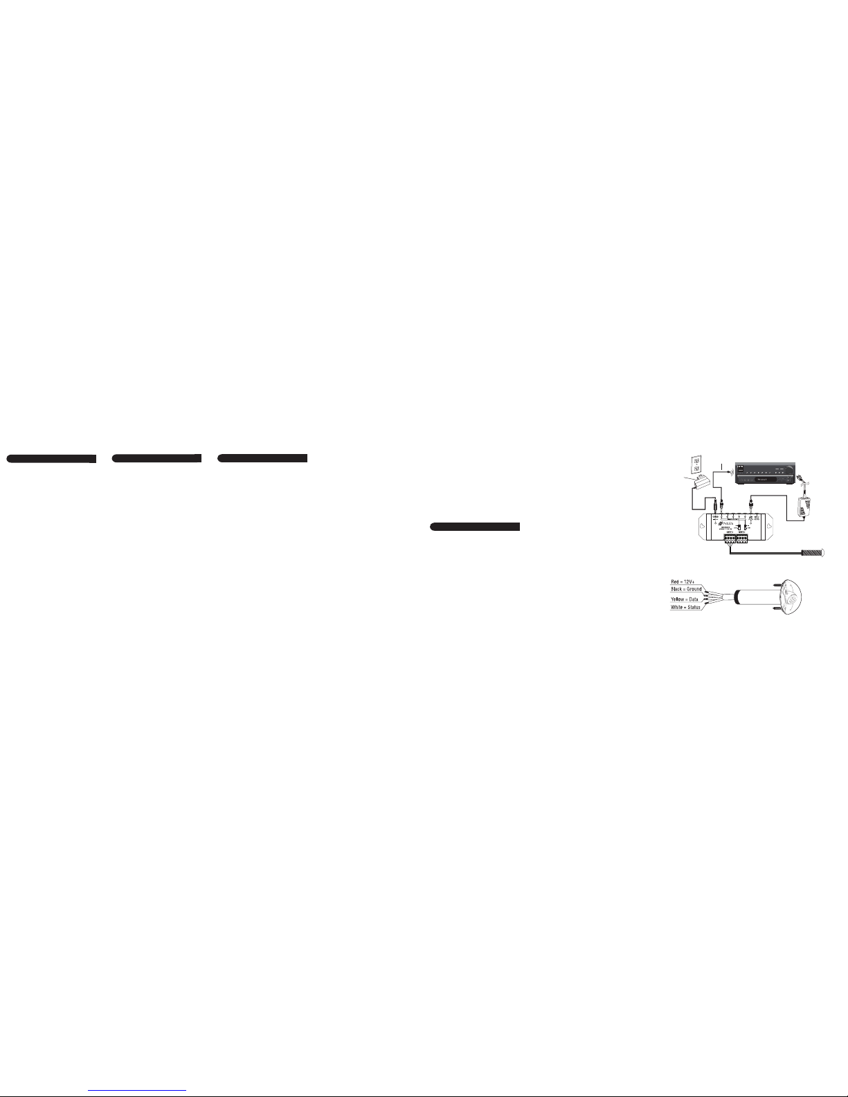
Figure 1 Wiring diagram
(installed in an MSU250 system)
Niles IR flasher
MSU250
CS120 IR sensor
Power, IR data, status signal and ground
via CAT-5 wire
Stereo receiver
12V DC power supply
(supplied with the
MSU250 main system
unit) plugged into an
unswitched AC outlet
powers the system
12V DC Power supply
(not supplied) plugged into the
switched outlet.
Niles stock# FG01035
Figure 2 Wiring legend