IR System
Compatible with virtually all brands
of remotes using carrier frequencies
between 20 and 110 kHz
IR Receiving Range
25’ to 40’ depending upon the
strength of the remote control
IR Receiving Angle
Omni-directional
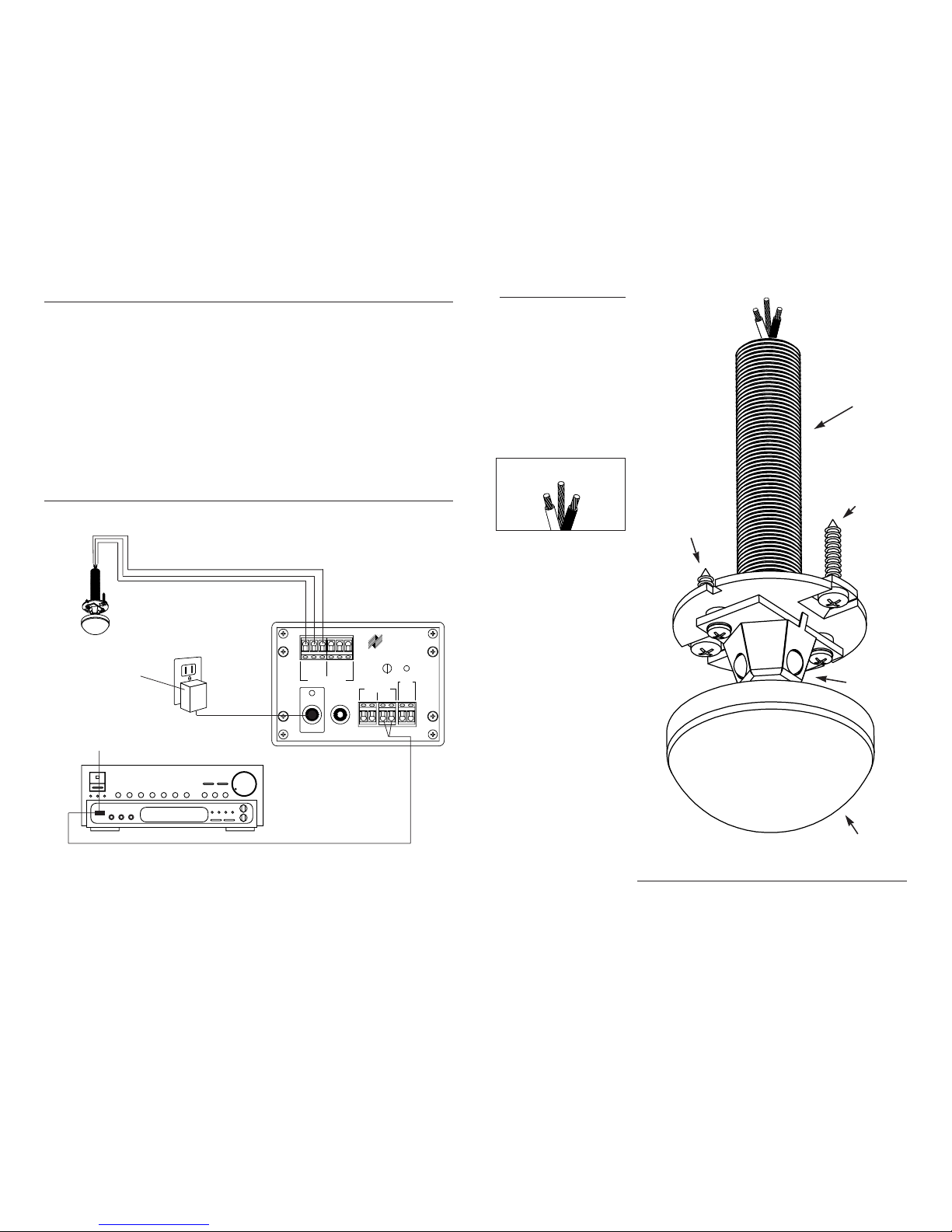
Mounting
Ceiling-mount, includes all mount-
ing hardware
Wiring Requirements
Individual “home-runs” of
2-conductor shielded cable,
West Penn D291 or equivalent
Unit Dimensions
1/2“ Wide x 2-7/8” Deep
LENS 1-1/2” Diameter x 5/8” High
This manual contains instructions
for the MS360 only. For specific
information on the adjustment
and operation of your Niles
infrared extender system, please
refer to the instruction manual
included with your Niles IR Main
System Unit.
IR Troubleshooting
There are four basic problems
which can prevent proper opera-
tion of your MS360 sensor. In the
order of probability, the problems
are as follows:
Bad Connections or Wiring
If the connections or wiring are
wrong, loose, shorted or open, the
system will not operate properly.
The symptoms may include inter-
mittent operation or no operation.
1. Test power supply connections.
2. Test your sensor connections.
3. Test your flasher connections.
4. Test your cable for shorts or
opens.
Flasher Level is Too High
Many audio/video components’
sensors are overloaded by receiv-
ing too strong of an IR command
from the flasher. Symptoms can
include: popping and clicking
sounds from the speakers when a
button is pressed on the remote
control, poor IR receiving range,
intermittent operation, or no
operation.
1. Connect the flasher(s) to the
variable output of the main sys-
tem unit, and reduce the output
level to one half.
2. Move the flasher further away
or off to the side of the sensor
window. Replace the sticky tab on
the flasher and only reapply when
you are sure the new location is
perfect.
Optical or Electromagnetic
Interference
Sunlight, reflections, neon signs
and other sources of electromag-
netic fields can induce noise and
interference into your IR extender
system. Common sources of elec-
tromagnetic interference may be:
Large direct-view televisions, wall-
mounted dimmers/ceiling fan
controls (these devices emit more
interference when turned down
halfway), fluorescent/neon/halo-
gen lights, and large appliances.
Symptoms can include poor IR
receiving range, intermittent oper-
ation, or no operation. To test the
system for freedom from interfer-
ence, carefully observe the IR test
LED on your IR Main System Unit.
If the LED does not flicker, you do
not have interference. If there is
any flickering of the LED, return to
the remote room location and use
tape or paper to entirely cover all
three of the sensing diodes (do
not use your hand—it will disrupt
the test with your body’s magnet-
ic field). Return to the IRP unit and
observe the IR LED on the IR Main
System Unit.
If the LED stops flickering you
have optical interference. Install
the sunlight filters over the sens-
ing diodes or if the interference is
weak, use the 1/2 strength filters.
If the LED continues to flicker when
the sensing diodes are completely
covered, the interference is not
optical, it is electromagnetic or RF.
Your options are:
1. Ground the MS360’s shield
(the bare wire) to a true earth
ground- preferably as close to the
MS360 as possible.
2. Replace with a Niles MS-1
miniature sensor. This sensor has
two fewer sensing diodes and is
thus 60% less sensitive to EMI.
3. Locate the source of interfer-
ence and move it or destroy it.
4. Find a location for the sensor
that is free of interference and
move the sensor, patch the ceiling
and repaint to match the existing
paint.
Optical Feedback Loop
If you have an IR sensor in the
same room as a flasher, and you
have some low-level noise or inter-
ference, an optical feedback loop
can occur which will interfere with
normal operation. Symptoms may
include: poor IR receiving range,
intermittent operation, or no
operation.
1. Replace IRC-1 flooding flashers
with IRC-2 stick-on flashers and
cover with the supplied IR block-
ing covers.
2. If equipment is housed in cabi-
netry, keep the doors closed when
using the IR repeater system.
Contact Niles Technical Support
at 1-800-289-4434 if you require
further assistance.
TROUBLESHOOTING
SPECIFICATIONS
Long Range MicroSensor™
Infrared Extender Circuitry
The Niles MS360 offers revolution-
ary real world range because of its
proven MicroSensor circuits. Based
on the acclaimed Niles MS-1 and
MS-2 MicroSensors, the MS360
incorporates cutting edge technolo-
gy to optimize range and reliability.
Niles engineers measured perfor-
mance in real world conditions
with interference. Backwards com-
patible with any Niles IR extender
system, the MS360 offers a new
level of convenience to anyone
using an IR extender system.
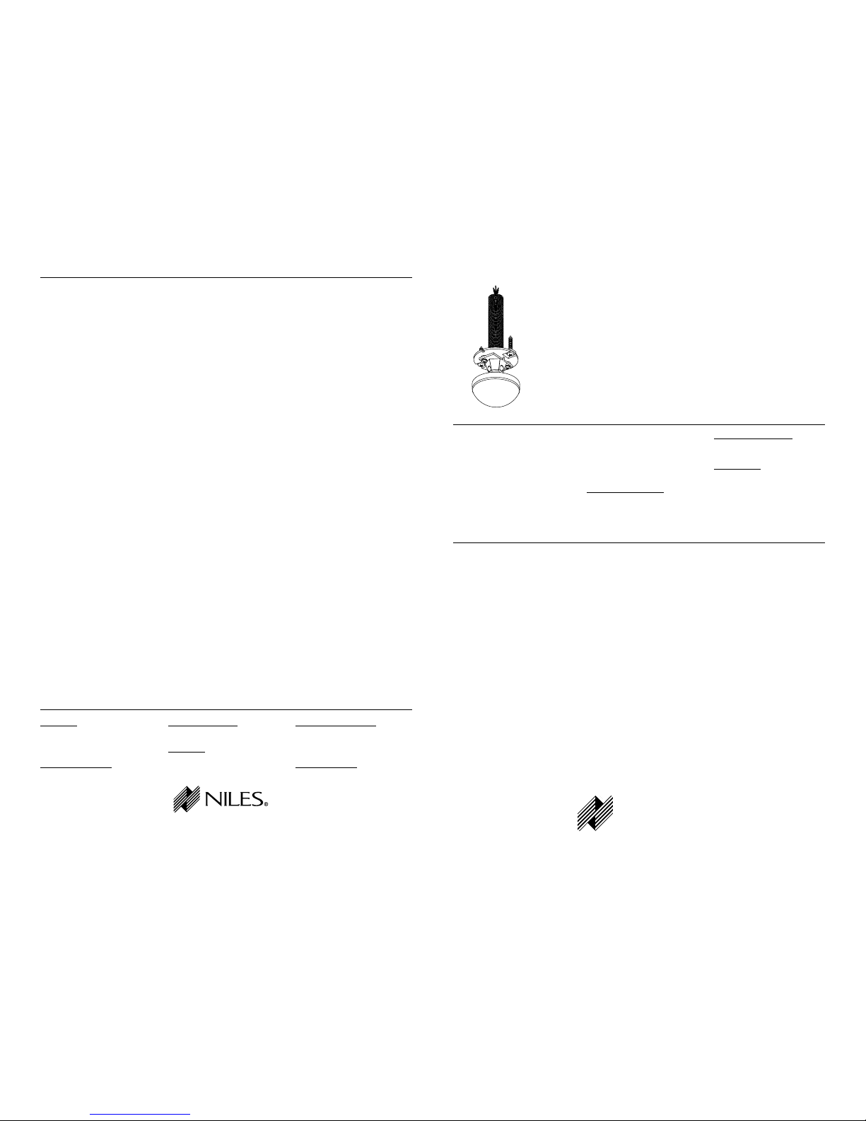
Small Size for a Discrete
Installation
The MS360 fits into a 1/2” open-
ing in the drywall, and the diame-
ter of the entire dome is only one
and one half inches. Additionally,
since all of the interior parts of the
new MS360 are pre-painted white
to blend in, the appearance of the
dome is very discrete.
Three Sensing Diodes Insure
360 Degree Coverage — The
World’s Only Omni-directional
IR Sensor
A conventional infrared sensor
mounted in the ceiling would direct
its cone of sensitivity straight down
— giving you inadequate range
from anywhere in the room except
directly underneath the sensor.
Niles engineers have cleverly com-
bined three separate sensing diodes
onto one mounting assembly to
give you enhanced range in all
directions. Advanced electronics
sum the three separate inputs with
incredible reliability and accuracy.
New Total Diode Shielding to
Prevent EMI
Not only is the housing of the
MS360 the same rigid EMI proof
metal cylinder used in the proven
MS-1, but the entire board incor-
porating the three sensing diodes
is surrounded with a carefully fit-
ted shield.
Filters For Optical
Interference
Each MS360 is supplied with
installer-friendly optical filters
enabling the installer to selectively
filter out sunlight or other types of
optical interference. Since the opti-
cal interference may be from only
one direction or from everywhere,
three filters of each type are sup-
plied. Full sunlight filters give a
range of twelve feet in direct sun-
light. Half sunlight filters prove
useful in bright rooms and typical-
ly give more than twenty feet
of range.
Made in the USA
Each MS360 is made with pride in
Miami, Florida USA.
FEATURES & BENEFITS
The MS360 is an omni-direction-
al, ceiling-mount infrared sensor
designed for use with the Niles
infrared extender systems.
Installed in a remote room loca-
tion, the MS360 receives the IR
commands transmitted from your
hand-held remote(s). The IR com-
mands are carried via a small
2-conductor shielded cable to
your A/V equipment in another
room, and instantly "repeated".
The MS360 represents one of the 3
building blocks necessary to com-
plete a Niles IR repeating system:
• IR Sensors/Keypads—Models
IRR4S+, IRR4D+, MS360, MS-1,
MS-2, TIR1+, RP-6, RP-7, RP-9
and the IntelliPad®
.
• IR Main System Unit
Models IRP2+, IRP6+, IRZ6+,
RVL-6 and MRZ-6.
• IR Flashers—Models IRC-1,
IRC-2, and IRC-2P.
An IR sensor expansion unit,
Model XRP6+, is available for IR
repeater systems used in more
than six rooms.
INTRODUCTION
NILES AUDIO CORPORATION 12331 SW 130 STREET MIAMI, FLORIDA 33186 TEL: (305) 238-4373 FAX: (305) 238-0185
WWW.NILESAUDIO.COM © 1999 Niles Audio Corporation. All rights reserved. Because Niles constantly strives to improve the quality of its
products, Niles reserves the right to change product specifications without notice. Niles, the Niles logo, IntelliPad and Blending High Fidelity and
Architecture are registered trademarks of Niles Audio Corporation. MicroSensor is a trademark of Niles Audio Corporation. Printed in USA 8/98
DS00221B
INSTALLATION & OPERATION GUIDE