Nilfisk cfm S2 User manual

Nilsk-CFM S.p.A. Via Porrettana 1991 - 41059 Zocca (Modena) Italy - Tel. +39 059 9730000 - Fax +39 059 9730099 - www.nilsk-cfm.com - info@nilsk-cfm.com
S2 - S3 service manual

S2 - S3 service manual 2
Table of contents
Preface ..........................................................................................................................................................................................page 3
Symbols ........................................................................................................................................................................................page 4
A Safety instructions...............................................................................................................................................................page 5
A.1 - Operator safety ............................................................................................................page 6
B Technical data.........................................................................................................................................................................page 9
B.1 - Technical data ............................................................................................................ page 10
C Components ........................................................................................................................................................................ page 11
C.1 - Trolley .......................................................................................................................... page 12
C.2 - Handle complete with cable carrier..................................................................... page 12
C.3 - Filtering chamber with complete inlet and deector ...................................... page 13
C.4 - Complete container ................................................................................................. page 14
C.5 - Accessories rack........................................................................................................ page 15
C.6 - Filter ring and seal ................................................................................................... page 16
C.7 - Filter with lter catch clamp ................................................................................. page 16
C.8 - Filter shaker cage ..................................................................................................... page 16
C.9 - Complete motor head............................................................................page 17
C.10 - Motor head closing band .....................................................................page 17
C.11 - Control panel.......................................................................................page 18
C.12 - Filter shaker system ..............................................................................page 18
D Vacuum cleaner operation ............................................................................................................................................ page 19
D.1 - Controls and indicators........................................................................................... page 20
E Troubleshooting................................................................................................................................................................. page 23
E.1 - Electrostatic discharge.............................................................................................. page 24
E.2 - Trolley ........................................................................................................................... page 25
E.3 - Filtering chamber with complete inlet and deector....................................... page 33
E.4 - Container .................................................................................................................... page 35
E.5 - Filter.............................................................................................................................. page 38
E.6 - Complete motor head ............................................................................................. page 41
F Spare parts............................................................................................................................................................................ page 68
F.1 - Spare parts................................................................................................................... page 69
G Instruments ......................................................................................................................................................................... page 70
G.1 - Special instruments.................................................................................................. page 71
H Wiring .................................................................................................................................................................................... page 72
H.1 - Wiring diagram ......................................................................................page 73

S2 - S3 service manual 3
Preface
This manual provides essential information required for repairing S2 - S3 series wet and dry vacuum cleaners.
When doing repairs, make sure you have a suitable workbench and the required electrical connection.
If particular anomalies are noticed during maintenance, please inform the customer who should have the user manual.
Appliance faults can be caused by several different factors. In this case refer to chapter E Troubleshooting.
For repairs, please refer to the list of spare parts indicating the positions of each component and the relevant sequence of as-
sembly.
Read the Technical Service Bulletins carefully with the technical modications performed after the manual was published.
The Technical Service Bulletins represent a supplement of the spare parts list until the next is published.
The manuals and bulletins must always be available during repairs. Other technical documents on the S2-S3 series may be re-
quired for repairs.
These documents should not be transferred to third parties.
ONLY USE ORIGINAL NILFISK-CFM SPARES!

S2 - S3 service manual 4
Symbols
Symbols used for instructions
The safety instructions indicated by this symbol in the manual must be observed to avoid injury
to persons.
This symbol is used to indicate the safety instructions which must be observed to prevent
damaging the vacuum cleaner and malfunctions.
This symbol indicates suggestions and instructions to simplify jobs and guarantee safe working
conditions.

A
Safety instructions

S2 - S3 service manual 6
A.1 - Operator safety
The repairs must only be carried out by personnel suitably trained for the job to do, or
a qualied electrician.
Before starting the vacuum cleaner, read these operating instructions carefully and keep them on hand for consultation.
The vacuum cleaner should only be used/serviced by people who are familiar with the way it works and who have been explic-
itly authorised and trained for the purpose.
Before using/servicing the vacuum cleaner, the operators must be informed, instructed and trained on how to use it and with
which substances it can be used, including the safe method for removing and disposing of the vacuumed material.
Use the vacuum cleaner in accordance with the laws in force in the country where it is used.
Besides the operating instructions and the laws in force in the country where the vacuum cleaner is used, the technical regula-
tions for ensuring safe and correct operation must also be observed (Legislation concerning environmental protection and
safety at work, i.e. European Union Directive 89/391/EC and following).
Do not perform any operation that could jeopardize the safety of people, property and the environment.
Comply with the safety indications and prescriptions in this service manual.
Observe the provisions of the directives and national safety regulations on the sale of electrical appliances, in particular
EN60335-2-69- En.AA
Vacuum cleaners for dust harmful to health are classied according to the following dust classication:
L (low risk) suitable for separating dust with an exposure limit value of at least 1 mg/m1. 3, depending on the volume occu-
pied; retains at least 99% of the vacuumed particles (See EN60335-2-69, Enclosure A.A);
M (medium risk) suitable for separating dust with an exposure limit value of at least 0.1 mg/m2. 3, depending on the volume
occupied; retains at least 99.9% of the vacuumed particles (See EN60335-2-69, Enclosure A.A);
H (high risk) for separating all dust with an exposure limit value lower than 0.1 mg/m3. 3, depending on the occupied vol-
ume, including carcinogenic and pathogenic dusts such as asbestos. Class H14 Hepa lter in accordance with standard EN
1822; retains at least 99.995% of vacuumed particles (See EN60335-2-69, Enclosure A.A).

S2 - S3 service manual 7
A.1 - Operator safety
Class L-M vacuum cleaners are identied by labels with pictograms of the following meaning.
.
This vacuum cleaner contains dust hazardous for the health.
Only authorised personnel wearing suitable personal protective
equipment should empty and service the vacuum cleaner, including
removing the means used to vacuum the dust. Do not use without
the complete lter system in place.
Class H vacuum cleaners are identied by a label with the following text.

S2 - S3 service manual 8
A.1 - Operator safety
Check the place of work and substances tolerated for the vacuum cleaner suitable for liquids.
WARNING - DANGER !
In the case of electrical vacuum cleaners/instruments connected to the vacuum cleaner,
always refer to the user manual and safety instructions.
WARNING - DANGER !
Take care not to raise dust during maintenance operations. Wear a P3 protective mask.

B
Technical specications

S2 - S3 service manual 10
B.1 - Technical data
PARAMETER UNIT OF MEASURE S2
L,M,H
S3
L,M,H
Voltage / frequency V/Hz 230/50-
60
230/50-
60
Power rating kW 2 3
Power rating (EN 60335-2-69) kW 1.8 2.6
Max. weight kg 67 73
Noise level (EN 60335-2-69) dB(A) 70 71
Protection IP 44 44
Insulation Class I I
Capacity L40 50 - 100
Dust bag capacity (versions M - H) L 32 32
Inlet mm Ø 70 Ø 70
Max vacuum hPa 211 211
Maximum air ow without hose and reductions L/min’ 5500 8070
Maximum air ow (3 m Ø 50 mm hose) L/min’ 4720 6500
Hoses allowed for “L” and “standard” classes mm Ø 70 Ø 70
Hoses allowed for “M” and “H” classes mm Ø 50 Ø 50
Primary lter surface (L-M) m21.95 1.95
Upstream absolute lter surface m23.5 3.5
Absolute lter efciency according to MPPS method (EN 1822) % 99.995
(H14)
99.995
(H14)
Note:
• Storage conditions: T :
-10 +40 °C - Humidity: ≤ 85%
• Operating conditions: Maximum altitude 800 m (up to 2,000 m with reduced performances)
T : -10 +40 °C - Humidity: ≤ 85%

C
Components
S2 - S3 service manual 12
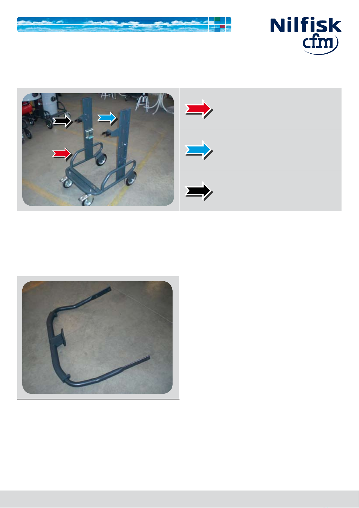
C.1 - Trolley
Trolley
Upright
Accessory support
C.2 - Handle complete with cable carrier

S2 - S3 service manual 13
C.3 - Filtering chamber with complete inlet and deector
Filtering chamber
Complete inlet
Deector
S2 - S3 service manual 14
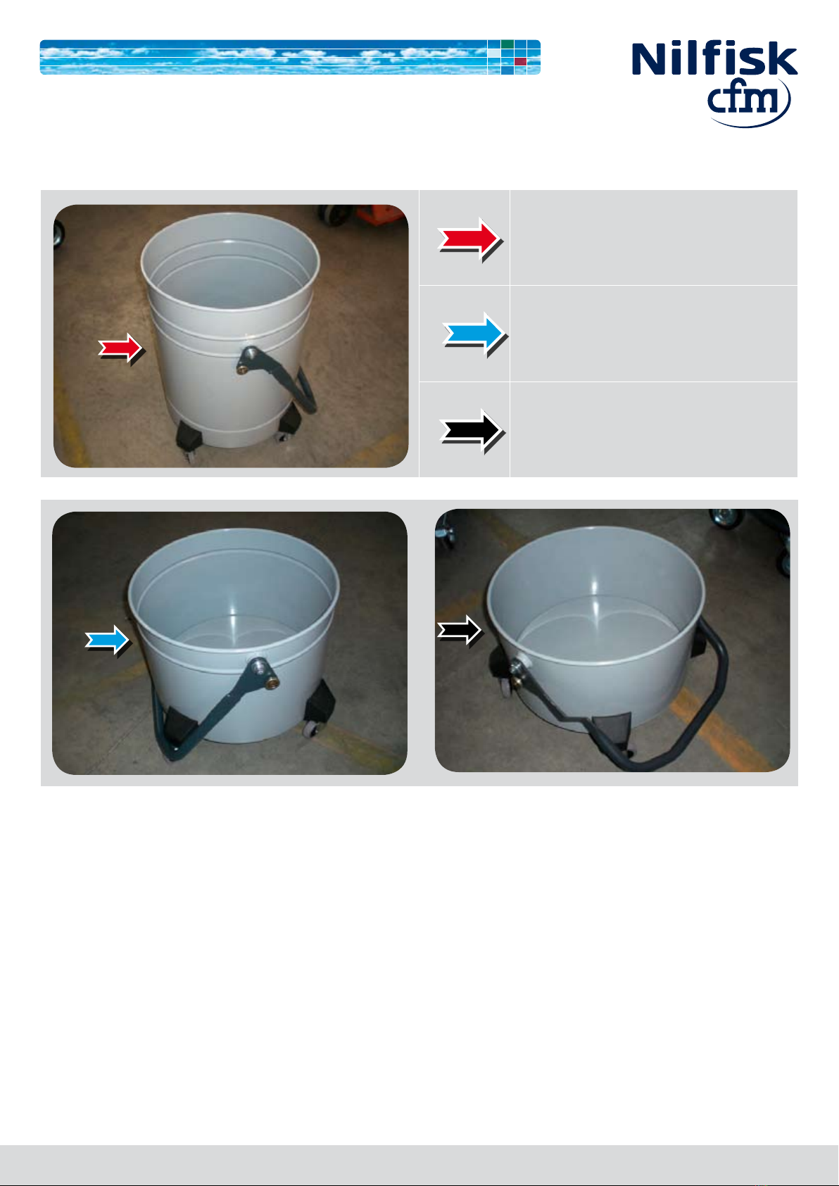
C.4 - Complete container
100 L container
50 L container
40 L container

S2 - S3 service manual 15
C.5 - Accessories rack
C.6 - Filter ring and seal
Filter ring
Filter ring seal

S2 - S3 service manual 16
C.7 - Filter with lter catch clamp
Filter
Filter catch clamp
C.8 - Filter shaker cage

S2 - S3 service manual 17
C.9 - Complete motor head with cable and plug
Motor head
Cable and plug
C.10 - Motor head closing band

S2 - S3 service manual 18
C.11 - Control panel
C.12 - Filter shaker system

D
Vacuum cleaner operation

S2 - S3 service manual 20
D.1 - Controls and indicators
Start/stop switch
2-way selector
Position 0 - The vacuum cleaner is turned OFF
Position 1 - The vacuum cleaner is powered and
starts
Main motor Start/Stop indicator and button If the indicator is lit, the main motor is ON. You can
start/stop the main motor with this button.
Second motor Start/Stop indicator and button If the indicator is lit, the second motor is ON. You
can start/stop the second motor with this button.
Third motor Start/Stop indicator and button If the indicator is lit, the third motor is ON. You can
start/stop the third motor with this button.
Stop button
When this button is pressed all the motors
stop simultaneously. The motors and internal
components of the vacuum cleaner will still be
electrically powered.
This manual suits for next models
1
Table of contents
Other Nilfisk cfm Vacuum Cleaner manuals


