Nilfisk cfm VHW 201 User manual

Nilsk-CFM S.p.A. Via Porrettana 1991 - 41059 Zocca (Modena) Italy - Tel. +39 059 9730000 - Fax +39 059 9730065 - www.nilsk-cfm.com - info@nilsk-cfm.com
VHW 201-211
Service Manual
SM VHW 201-211 10/14

VHW 201 - 211 Service Manual 2
Table of contents
Preface ...................................................................................................................................................... page 3
Symbols .................................................................................................................................................... page 4
Safety guidelines ..................................................................................................................................... page 5
A.1 - Operator safety ........................................................................................ page 6
B Technical data........................................................................................................................................ page 8
B.1 - Technical data........................................................................................... page 9
C Components.......................................................................................................................................... page 10
C.1 - Front side ................................................................................................. page 11
C.2 - Rear side .................................................................................................. page 11
C.3 - Optional exhaust silencer.......................................................................... page 12
C.4 - Filter, inlet, and deector .......................................................................... page 13
D Operation.............................................................................................................................................. page 14
D.1 - Controls and indicators............................................................................. page 15
E Troubleshooting.................................................................................................................................... page 16
E.1 - ESD (electrostatic discharge)...................................................................... page 17
E.2 - Initial operations ....................................................................................... page 18
E.3 - Electrical panel .......................................................................................... page 21
E.4 - Motor ....................................................................................................... page 23
E.5 - Base.......................................................................................................... page 31
E.6 - Container and lter................................................................................... page 33
F Spare parts............................................................................................................................................. page 36
F.1 - Spare parts ................................................................................................ page 37
G Tools ...................................................................................................................................................... page 38
G.1 - Special tools ............................................................................................. page 39
H Wiring.................................................................................................................................................... page 40
H.1 - Wiring diagram ........................................................................................ page 41

VHW 201 - 211 Service Manual 3
Preface
This manual provides essential information for repairing VHW 201- 211 series vacuum cleaners.
When doing repairs, make sure that a suitable workbench and the required electrical connection are available.
If particular anomalies are noticed during maintenance, please inform the customer who should have the user manual.
Appliance faults can be caused by several different factors. In this case refer to chapter E Troubleshooting.
For repairs, please refer to the list of spare parts indicating the positions of each component and the relevant sequence of as-
sembly.
Read the Technical Service Bulletins carefully with the technical modications performed after the manual was published.
The Technical Service Bulletins represent a supplement of the spare parts list until the next is published.
The manuals and bulletins must always be available during repairs. Other technical documents on the VHW 200- 210 series may
be required for repairs.
These documents should not be transferred to third parties.
ONLY USE ORIGINAL NILFISK-CFM SPARES!

VHW 201 - 211 Service Manual 4
Symbols
Symbols used for instructions
The safety instructions indicated by this symbol in the manual must be observed to avoid injury
to persons.
This symbol is used to indicate the safety instructions which must be observed to prevent
damaging the vacuum cleaner and malfunctions.
This symbol indicates suggestions and instructions to simplify jobs and guarantee safe working
conditions.

A
Safety instructions

VHW 201 - 211 Service Manual 6
A.1 - Operator safety
The repairs must only be carried out by personnel suitably trained for the job to do, or
a qualied electrician.
Before starting the vacuum cleaner, read these operating instructions carefully and keep them on hand for consultation.
The vacuum cleaner should only be used/serviced by people who are familiar with the way it works and who have been explic-
itly authorised and trained for the purpose.
Before using/servicing the vacuum cleaner, the operators must be informed, instructed and trained on how to use it and with
which substances it can be used, including the safe method for removing and disposing of the vacuumed material.
Use the vacuum cleaner in accordance with the laws in force in the country where it is used.
Besides the operating instructions and the laws in force in the country where the vacuum cleaner is used, the technical regula-
tions for ensuring safe and correct operation must also be observed (Legislation concerning environmental protection and
safety at work, i.e. European Union Directive 89/391/EC and following).
Do not perform any operation that could jeopardize the safety of people, property and the environment.
Comply with the safety indications and prescriptions in this service manual.
Observe national laws and safety regulations on the sale of electrical appliances, in particular EN60335-2-69- Ann.AA

VHW 201 - 211 Service Manual 7
A.1 - Operator safety
Check the place of work and substances tolerated for the vacuum cleaner suitable for liquids.
WARNING - DANGER !
In the case of electrical vacuum cleaners/instruments connected to the vacuum cleaner,
always refer to the user manual and safety instructions.
WARNING - DANGER !
Unplug the vacuum cleaner from the socket before doing any maintenance, replacing
parts or transforming the unit. The plug must be removed from the socket.
Only perform the maintenance described in this manual.
Only use original spare parts.
Do not modify the vacuum cleaner in any way. Operations performed without
observing the following instructions can be hazardous and invalidate the declaration
of conformity issued and enclosed with the machine.
WARNING - DANGER !
Contact an authorized service centre to perform any maintenance which is not
described in this manual.
WARNING - DANGER !
Take care not to raise dust during maintenance operations. Wear a P3 protective mask.

B
Technical data

VHW 201 - 211 Service Manual 9
B.1 - Technical data
PARAMETER UNIT OF
MEASURE VHW 201 VHW 211
Voltage/Frequency Volts/Hz 400/50 400/50
Power rating kW 0.45 0.85
Max. weight Kg 35 36
Noise level dB(A) 62 59
Protection IP 55 55
Insulation Class I I
Container capacity L6.5 6.5
Inlet mm Ø 40 40
Max vacuum hPa - mbar 148-148 210-210
Maximum air ow without hose and reductions m3/h - L/min 71,5-1192 116-1933
Max. airow (m3 Ø 50 mm hose) m3/h - L/min 70-1167 114-1900
Main lter surface m20.193 0.193
Upstream/downstream absolute “H” lter surface- HEPA
14 according to MPPS method (EN1822) m21.1 1.1
Notes:
• Storage conditions: T :
-10 +40°C - Humidity: ≤ 85%
• Operating conditions: Maximum altitude 800 m (up to 2000 m with reduced performance) - T:
-10 +40°C - Humidity: ≤ 85%

C
Components

VHW 201 - 211 Service Manual 11
C.1 Front side
Lid
Container
Base
C.2 - Rear side
Electrical panel
Exhaust silencer on basic versions
(only VHW 211)
VHW 201 - 211 Service Manual 12
C.3 Optional exhaust silencer
Exhaust silencer on Atex and/or AD versions

VHW 201 - 211 Service Manual 13
C.4 - Filter, inlet, and deector
Ring
Filter
Seal
Inlet
Deector

D
Vacuum cleaner operation

VHW 201 - 211 Service Manual 15
D.1 - Controls and indicators
Start/stop switch • Turn the vacuum cleaner on and off with the on/off switch of the electrical
system.
Wait to let the dust settle before restarting the vacuum cleaner. If the lter is still clogged, clean
it and/or replace it.

E
Troubleshooting

VHW 201 - 211 Service Manual 17
E.1 - Electrostatic discharge
Take the following precautions to discharge
electrostatic charges before doing any repairs on the
electrical circuits:
• Touch the protective conductor to discharge any static
electricity charge in the body;
• If possible, wear an antistatic bracelet;
• Use antistatic mats;
• Never touch a circuit board or electronic components,
always hold them with plastic or insulated tools;
• Transport electronic components in conductive
packaging (special packs to discharge electrostatic
charges for example).
Before proceeding with these operations, turn off
the vacuum cleaner and remove the plug from the
power socket.

VHW 201 - 211 Service Manual 18
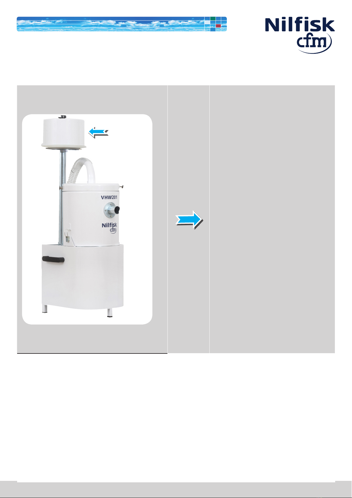
E.2 - Initial operations
Remove the suction hose.
Remove the lid by pulling the knob.
Remove the container opening the two latches.

VHW 201 - 211 Service Manual 19
E.2 - Initial operations
Remove the container.
Remove the suction hose from the blower.

VHW 201 - 211 Service Manual 20
E.2 - Initial operations
Remove the diffuser container by unscrewing the knob.
Remove the exhaust connection by unscrewing it.
This manual suits for next models
1
Table of contents
Other Nilfisk cfm Vacuum Cleaner manuals


