Nilfisk cfm VHW320 User manual

VHW320
VHW321
VHW420
VHW421
VHW440
C393-I-GB-F-D-E
09/2014
I
GB
F
D
E
MANUALE DI ISTRUZIONI
INSTRUCTIONS MANUAL
MANUEL D’INSTRUCTIONS
BETRIEBSANLEITUNG
MANUAL DE INSTRUCCIONES


VHW320 - VHW321 - VHW420 - VHW421 - VHW440
09/2014 1C393
GB
Table of contents
Instructions for use.........................................................................................................3
Operator’s safety............................................................................................................................. 3
General information for using the vacuum cleaner.......................................................................... 3
Proper uses..................................................................................................................................... 3
Improper Use................................................................................................................................... 3
Versions and variations ................................................................................................................... 4
Classication in compliance with standard EN 60335-2-69 – Annexe AA....................................... 4
Dust emissions in the environment ................................................................................................. 4
General recommendations.............................................................................................................. 4
In case of accident or breakdown.................................................................................................... 4
EC Declaration of conformity........................................................................................................... 4
Vacuum cleaner description...........................................................................................5
Parts and labels............................................................................................................................... 5
Optional kits..................................................................................................................................... 5
Accessories..................................................................................................................................... 5
Packing and unpacking ................................................................................................................... 6
Unpacking, moving, use and storage.............................................................................................. 6
Setting to work - connection to the power supply............................................................................ 6
Extensions....................................................................................................................................... 7
Dry applications............................................................................................................................... 7
Maintenance and repairs................................................................................................................. 7
VHW320 - VHW321 Technical Data................................................................................................ 8
Dimensions...................................................................................................................................... 8
VHW420 - VHW421 - VHW440 Technical Data .............................................................................. 9
Dimensions...................................................................................................................................... 9
Safety devices............................................................................................................................... 10
Controls, indicators and connections ............................................................................................ 10
Inspections prior to starting ........................................................................................................... 10
Starting and stopping .................................................................................................................... 10
Vacuum cleaner operation............................................................................................................. 10
Main lter cleaning ........................................................................................................................ 10
Primary cartridge lter cleaning (InniClean) .................................................................................11
Emergency stopping.......................................................................................................................11
Emptying the container...................................................................................................................11
Plastic bag (Class L only)...............................................................................................................11
Versions for dusts harmful to health...............................................................................................11
Paper bag.......................................................................................................................................11
Safe Dust Bag ................................................................................................................................11
Replacement of hazardous dust bags............................................................................................11
At the end of a cleaning session ................................................................................................... 12
Maintenance, cleaning and decontamination................................................................................ 12
Main lter disassembly and replacement ...................................................................................... 13
Main cartridge lter replacement, models with PullClean.............................................................. 13
Cartridge replacement (InniClean Models).................................................................................. 13
Upstream absolute lter replacement............................................................................................ 14
Downstream absolute lter replacement....................................................................................... 14
Motor cooling fan inspection and cleaning .................................................................................... 14
Tightness inspection...................................................................................................................... 14
Vacuum cleaner disposal .............................................................................................................. 15
Translation of original instructions

C393 209/2014
VHW320 - VHW321 - VHW420 - VHW421 - VHW440
GB
Wiring diagrams ............................................................................................................................ 15
VHW320 - VHW321 Recommended Spare Parts......................................................................... 16
VHW420 - VHW421 - VHW440 Recommended Spare Parts ....................................................... 17
Troubleshooting ............................................................................................................18

VHW320 - VHW321 - VHW420 - VHW421 - VHW440
09/2014 3C393
GB
Instructions for use
Proper uses
This vacuum cleaner is suitable for commercial use, in hotels,
schools, hospitals, factories, shops, ofces and apartment
buildings, for hire and in any case for purposes other than
normal domestic use.
This vacuum cleaner was conceived to clean and collect solid
non-ammable materials indoor and outdoor.
WARNING – This vacuum cleaner can only be used to
vacuum dry materials.
■ Always leave enough room around the device to reach
the controls easily.
The device has been designed to be used by one operator at
a time.
This vacuum cleaner consists of an automated vacuum
unit, with a lter upstream and a container for collecting the
vacuumed material.
Improper use
WARNING!
The following use of the device is strictly forbidden:
■Outdoors in case of atmospheric precipitation.
■When not placed on level grounds.
■When the ltering unit is not installed.
■When the vacuum inlet and/or hose are turned to
parts of the human body.
■When the dust bag is not installed.
■Use without the guards, protective covers and
safety systems installed by the manufacturer.
■When the cooling vents are partially or totally
clogged.
■When the vacuum cleaner is covered with plastic or
fabric sheets.
■When the air outlet is partially or totally closed.
■When used in narrow areas where there is no fresh
air.
■Vacuuming the following materials:
1. Burning materials (embers, hot ashes, lit
cigarettes, etc.).
2. Open ame
3. Combustible gas.
4. Flammable liquids, aggressive fuels (gasoline,
solvents, acids, alkaline solutions, etc.).
5. Explosive dust/substances and/or ones liable
to ignite in a spontaneous way (such as
magnesium or aluminium dusts, etc.).
IMPORTANT: Fraudulent use is not permitted.
Read the operating instructions and comply with the important safety recommendations identied by the
word WARNING!
Operator’s safety
WARNING!
Before starting the device, it is absolutely
essential to read these operating
instructions and to keep them ready at hand
for consultation.
The vacuum cleaner can only be used by people who
are familiar with the way it works and who have been
explicitly authorized and trained for the purpose.
Before using the device, the operators must be
informed, instructed and trained on how to work it and
for which substances its usage is permitted including
the safe method for removing and disposing of the
vacuumed material.
WARNING!
The use of the device by people (including children)
with limited physical and mental capacities or lacking
in experience and knowledge is strictly forbidden,
unless they are supervised by a person who is
experienced in the use and safe handling of the
machine.
Children must be supervised to make sure they will
not play with the device.
General information for using the vacuum
cleaner
Use the vacuum cleaner in accordance with the laws in force
in the country where it is used.
Besides the operating instructions and the laws in force in the
country where the device is used, the technical regulations for
ensuring safe and correct operation must also be observed
(Legislation concerning environmental and labour safety,
i.e. European Union Directive 89/391/EC and successive
Directives).
Do not perform any operation that could jeopardize the safety
of people, property and the environment.
Comply with the safety indications and prescriptions in this
instruction manual.

C393 409/2014
VHW320 - VHW321 - VHW420 - VHW421 - VHW440
GB
Versions and variations
Versions
WARNING!
Dust classication
Versions for dust harmful to health:
classes L, M, H, the vacuum cleaner is suitable for use
with hazardous, non-combustible/non-explosive dust
in accordance with standard EN 60335-2-69, Annexe
AA.
Check the tolerated dust hazard class on the data
plate and on the label on the vacuum cleaner: L (low
risk), M (medium risk), H (high risk).
[ NOTE ]
■In the case of dust harmful to health, contact the local
health and safety authorities, and observe national
regulations in force both during use and disposal.
■Radioactive substances are not included in the
denition of the type of dust dust harmful to health
described above.
Variants
ATEX
[ NOTE ]
ATEX variants
Refer to the manufacturer’s sales network for these versions.
For ATEX industrial devices see the instructions for “ATEX”
use.
The manufacturer produces vacuum cleaners suitable to be
used in potentially explosive atmospheres. These variants are
manufactured according to directives and standards in force.
The relevant additional instructions are supplied together with
the device.
Classication in compliance with standard
EN 60335-2-69 – Annexe AA
Vacuum cleaners for dust harmful to health are classied
according to the following dust classication:
■L (low risk) suitable for separating dust with an exposure
limit value of over 1 mg/m3, depending on the volume
occupied;
■M (medium risk) suitable for separating dust with
an exposure limit value of no lower than 0.1 mg/m3,
depending on the volume occupied;
■H (high risk) for separating all dust with an exposure limit
value lower than 0.1 mg/m3, depending on the volume
occupied, including carcinogenic and pathogenic dusts,
such as asbestos.
Dust emissions in the environment
Indicative values of performance:
■ normal version (not suitable for vacuuming hazardous
dust): retains at least 99% of the vacuumed particles
(see EN60335-2-69, Annexe AA);
■ version for dust harmful to health (Classes L, M, H):
L: retains at least 99% of the vacuumed particles
(see EN60335-2-69, Annexe AA);
M: retains at least 99.9% of the vacuumed particles
(see EN60335-2-69, Annexe AA);
H: retains at least 99.995% of the vacuumed
particles (see EN60335-2-69, Annexe AA).
General recommendations
WARNING!
If an emergency situation occurs:
■lter breakage
■re outbreak
■short-circuit
■motor block
■electric shock
■etc.
Turn the vacuum cleaner off, unplug it and request
assistance from qualied personnel.
[ NOTE ]
Check the place of work and substances tolerated for the
vacuum cleaner in ATEX variant.
WARNING!
The vacuum cleaners must not be used or stored
outdoors in damp places.
These devices cannot be used in corrosive environments.
In case of accident or breakdown
In case of accident or vacuum cleaner breakdown, disconnect
the equipment from the power supply.
In case the user comes into contact with the vacuumed
product, check the cautions shown on the safety technical
sheet of the product, which must be made available from the
employer.
EC Declaration of conformity
Every vacuum cleaner comes with a EC Declaration of
conformity. See fac-simile in g. 23.
[ NOTE ]
The Declaration of conformity is an important document
and should be kept in a safe place to be presented to the
Authorities on request.

VHW320 - VHW321 - VHW420 - VHW421 - VHW440
09/2014 5C393
GB
Vacuum cleaner description
This vacuum cleaner creates a strong air ow which is drawn
in through the inlet (5, Fig. 1) and blows out through the
exhaust (4, Fig. 1). After the hose and tools have been tted,
make sure that the motor turns correctly.
The vacuum cleaner is supplied with a check valve (clapet)
which prevents air and materials from coming out of the dust
container, even if the electric motor rotates in the opposite
direction than the one expected.
Before turning on the vacuum cleaner, t the vacuum hose
into the inlet and then t the required tool on to the end part.
Refer to the manufacturer’s accessory catalogue or Service
Center.
The diameters of the authorized hoses are indicated in the
Technical data table.
The vacuum cleaner is equipped with a main lter which
enables it to be used for the majority of applications.
Besides the main lter which retains the more common types
of dust, the vacuum cleaner can be tted with an upstream
absolute lter and a downstream absolute lter, with a higher
ltering capacity for ne dust and substances that pose a
health risk.
Optional kits
Please contact the manufacturer’s sales network for
information on optionals.
Instructions for installing the optional are included in the
conversion kit.
WARNING!
Use only genuine optional kits supplied and
authorized by the manufacturer.
Accessories
Various accessories are available; refer to the manufacturer’s
accessory catalogue.
WARNING!
Use only genuine accessories supplied and authorized
by the manufacturer.
WARNING!
ATEX variants: refer to the manufacturer’s sales
network.
Parts and labels
Figure 1
1. Identication plate which includes:
▪Manufacturer’s name and address
▪Designation and model, including class (L, M or H)
▪EC Mark
▪Technical data
▪Serial number
▪Year of manufacture
▪Weight (kg)
2. Warning label
(For L, M, H version)
3. Panel power plate
Indicates that the panel is powered by the voltage
indicated on the data plate.
4. Outlet
5. Inlet
6. Vacuum gauge
7. Container
8. Container release lever
9. On/off switch
10. PullClean lter cleaning system
11. Cap closing levers
12. Shutter valve
Figure 2
1. Class L label
2. Class M label
3. Class H label
The class L and M labels contain pictograms with the following
meanings:
WARNING!
This vacuum cleaner contains dust hazardous
for the health.
Only authorized personnel wearing suitable
personal protective equipment should empty
and service the vacuum cleaner, including removing
the means used to vacuum the dust. Do not use
without the complete lter system in place.
The class H label contains the above text.
C393 609/2014
VHW320 - VHW321 - VHW420 - VHW421 - VHW440
GB
Packing and unpacking
Dispose of the packing materials in compliance with the laws
in force.
Figure 3
VHW320 MODEL A
(mm)
B
(mm)
C
(mm) kg
L - M - H 500 900 1360 86
ATEX Z22 500 900 1360 86
ATEX Z2 500 900 1360 91
IC 500 900 1630 107
VHW321 MODEL A
(mm)
B
(mm)
C
(mm) kg
L - M 500 900 1360 91
H500 900 1360 96
ATEX Z21 500 900 1360 99
ATEX Z22 500 900 1360 91
ATEX Z2 500 900 1360 96
VHW420 MODEL A
(mm)
B
(mm)
C
(mm) kg
STD 620 1050 1660 121
ATEX Z22 620 1050 1660 121
IC 620 1050 1950 153
C620 1050 1950 162
VHW421 MODEL A
(mm)
B
(mm)
C
(mm) kg
L - M 620 1050 1660 136
H620 1050 1660 139
ATEX Z21 620 1050 1660 149
ATEX Z22 620 1050 1660 136
VHW440 MODEL A
(mm)
B
(mm)
C
(mm) kg
STD 620 1050 1660 134
IC 620 1050 1950 165
C620 1050 1950 175
Unpacking, moving, use and storage
Operate on at, horizontal surfaces.
The load-bearing capacity of the surface the vacuum cleaner
is placed on must be suitable for bearing its weight.
Setting to work - connection to the power
supply
WARNING!
■Make sure there is no evident sign of damage to
the vacuum cleaner before starting work.
■Before plugging the vacuum cleaner into the
electrical mains, make sure the voltage rating
indicated on the data plate corresponds to that of
the electrical mains.
■Plug the vacuum cleaner into a socket with a
correctly installed ground contact/connection.
Make sure that the vacuum cleaner is turned off.
■The plugs and connectors of the power supply
cords must be protected against splashes of water.
■Check for proper connection to the electrical
mains.
■Use the vacuum cleaner only when the cord
that connects to the electricity mains is in good
condition (damaged cords could lead to electric
shock!).
■Regularly check there are no signs of damage,
excessive wear, cracks or aging on the electric
cord.
WARNING!
When the device is operating, do not:
■Crush, pull, damage or tread on the cord that
connects to the electrical mains.
■Only disconnect the cord from the electrical mains
by removing the plug (do not pull the cord).
■Only replace the electric power supply cord with
one of the same type as the original: FROR, the
same rule applies if an extension is used.
■The cord must be replaced by the manufacturer’s
Service Center staff or by equivalent qualied
personnel.

VHW320 - VHW321 - VHW420 - VHW421 - VHW440
09/2014 7C393
GB
Extensions
If an extension cord is used, make sure it is suitable for the
power input and protection degree of the vacuum cleaner.
WARNING!
ATEX variant: extensions, plugged in electrical devices
and adapters cannot be used when the vacuum
cleaner is used for ammable dust.
Minimum section of extension cords:
Maximum length = 20 m
Cord = FROR
Max power (kW) 1.5 35
Minimum section (mm2) 1.5 2.5 4
WARNING!
Sockets, plugs, cord grips, connectors and installation
of the extension cord must maintain the IP protection
degree of the vacuum cleaner, as indicated on the data
plate.
WARNING!
The vacuum cleaner’s power socket must be protected
by a differential circuit-breaker with surge current
limitation that shuts off the power supply when the
current discharged to the ground exceeds 30 mA for
30 msec. or an equivalent protection circuit.
WARNING!
Never spray water on the vacuum cleaner: this could
be dangerous for persons and could short circuit the
power supply.
WARNING!
Comply with the safety regulations governing the
materials for which the vacuum cleaner is used.
Dry applications
[ NOTE ]
The supplied lters and the dust (if applicable) must be
installed correctly.
WARNING!
Comply with the safety regulations governing the
materials for which the vacuum cleaner is used.
Maintenance and repairs
WARNING!
Disconnect the vacuum cleaner from its power
source before cleaning, servicing, replacing parts or
converting it to obtain another version/variant. The
plug must be removed from the socket.
■Carry out only the maintenance operations
described in this manual.
■Use only original spare parts.
■Do not modify the vacuum cleaner in any way.
Failure to comply with these instructions could
jeopardize your safety. Moreover, such action would
immediately void the EC declaration of conformity
issued with the device.

C393 809/2014
VHW320 - VHW321 - VHW420 - VHW421 - VHW440
GB
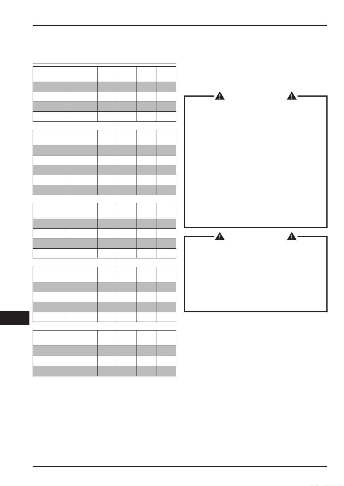
VHW320 - VHW321 Technical Data
Parameter Units VHW320IC VHW320 VHW321
Dust classes - L - M - H
Voltage (50 Hz) V 400 400 400
Power rating kW 1.5 1.5 1.5
Power rating (EN 60335-2-69) (50 Hz) kW 1.4 1.4 1.4
Power (VHW.. Z21 - VHW.. Z2) kW -2.2 2.2
Power rating (VHW.. Z22) kW - 1.6 1.6
Noise level (Lpf) (EN60335-2-69) dB(A) 60 60 61
Protection IP 55 55 55 / 65(**)
Electrical protection Class I I I
Motor insulation class Class F F F
Container capacity L 25 25 25
Inlet (diameter) mm 50 50 50
Max vacuum with limiting valve (VHW.. L/M/H) hPa - mbar 185 185 185
Max vacuum with limiting valve (VHW..Z21 - VHW.. Z2) hPa - mbar - - 170
Max vacuum with limiting valve (VHW..Z22) hPa - mbar - 200 200
Maximum air ow rate(without hose and reductions) m3/h - L/min’ 192 - 3200 192 - 3200 192 - 3200
Maximum air ow rate (with hose, length: 3 m, diameter: 40 mm) m3/h - L/min’ 160 - 2470 160 - 2670 160 - 2670
Allowed hoses mm 40 - 50 40 40
Main cartridge lter surface m21.5 1 1
Upstream absolute “H” lter surface m2-1.1 1.1
Absolute lter efciency (EN 1822) % - 99.995 (H14) 99.995 (H14)
Blower absolute lter surface area m21.1 1.1 1.1
Downstream absolute lter efciency (EN1822) % 99.995 (H14) - 99.9995 (U15)
Dimensions
Figure 4
Model VHW320 VHW321
L - M - H - Z22 IC L - M - H - Z22 Z2 Z21
A (mm) 1170 1370 1170 1170
B (mm) 780 800 735
C (mm) 440 440 440
Weight (kg) 73 94 83 88 91
■Storage conditions: T: -10°C ÷ +40°C Humidity: 85%
■Operating conditions:
Maximum altitude: 800 m (Up to 2,000 m with reduced performances)
T: -10°C ÷ +40°C Humidity: 85%

VHW320 - VHW321 - VHW420 - VHW421 - VHW440
09/2014 9C393
GB
VHW420 - VHW421 - VHW440 Technical Data
Parameter Units VHW420 VHW420C VHW420IC VHW421 VHW440 VHW440C VHW440IC
Dust classes - - - L - M - H - - -
Voltage (50 Hz) V 400
Power rating kW 2,2 4
Power rating (EN 60335-2-69) (50 Hz) kW 2,1 2,7 2,7 2,7
Power (VHW.. Z21 - VHW.. Z2) kW - - - 4- - -
Power (VHW.. Z22) kW 2,2 - 2,2 4 4 -
Noise level (Lpf) (EN60335-2-69) dB(A) 63 65 67
Protection IP 55 55 / 65(**) 55
Electrical protection Class I
Motor insulation class Class F
Container capacity L 46
Inlet (diameter) mm 70 70/50(***) 70
Max vacuum (VHW.. L/M/H) hPa - mbar 190 230 -
Max vacuum (VHW..Z21 - VHW.. Z2) hPa - mbar - - - 210 - - -
Max vacuum (VHW..Z22) hPa - mbar 190 -190 200 200 -
Maximum air ow rate (without hose and reductions) m3/h - L/min’ 306 - 5100 420-7000
Maximum air ow rate(without hose and reductions) m3/h - L/min’ 237 - 3950 280-4670
Allowed hoses mm 70 - 50 70 (*) - 50 70-50
Main cartridge lter surface m225,25 2,5 2 2 5,25 2,5
Upstream absolute “H” lter surface m2- 3,5 2,1 2,1 3,5
Absolute lter efciency (EN 1822) % - 99,995
(H14) -99,995
(H14) 99,995 (H14)
Blower absolute lter surface area m22,1
Downstream absolute lter efciency (EN1822) % 99,995 (H14)
(*) “L” versions only
(**) VHW.. Z21
(***) “M-H” versions only
Dimensions
Figure 4
Model
VHW420 VHW421 VHW440
STD / Z22 IC C
Z21 Z22
STD C IC
L M H L M H L M H
A (mm) 1390 1730 1560 1390 1390 1730 1560
B (mm) 970
C (mm) 540
Weight (kg) 100 133 135 113 118 113 118 113 118 113 153 143
■Storage conditions: T: -10°C ÷ +40°C Humidity: 85%
■Operating conditions:
Maximum altitude: 800 m (Up to 2,000 m with reduced performances)
T: -10°C ÷ +40°C Humidity: 85%
Safety devices
C393 10 09/2014
VHW320 - VHW321 - VHW420 - VHW421 - VHW440
GB
Figure 5
1. Vacuuming unit
2. Limiting valve
3. Clapet
WARNING!
Do not tamper any limiting valve setting.
Controls, indicators and connections
Figure 6
1. Dust container release lever
2. Castor lever
3. PullClean lter cleaning system
4. Vacuum gauge
5. Start/stop switch
6. Electric power cable
7. Handle
8. Shutter valve
Inspections prior to starting
Figure 7
1. Inlet
Prior to starting, check that:
■ the lters are installed
■all latches are tightly locked
■ the vacuum hose and tools have been correctly tted into
the inlet (1)
■ the bag or safety dust container is installed, if applicable.
WARNING!
Do not use the device if the lter is faulty.
Starting/stopping the vacuum cleaner
Figure 8
WARNING!
Lock the caster brakes (1) before starting the vacuum
cleaner.
■ Turn the switch (2) to “I” position to start the vacuum
cleaner.
■ Turn the switch to “0” position to turn the vacuum cleaner
off.
Vacuum cleaner operation
Checking the rotation direction of the vacuum unit
motor
Check the vacuum cleaner operation by putting a hand on the
inlet.
If the vacuum cleaner does not vacuum any air, the motor
rotation direction is wrong; disconnect the machine from the
electrical mains and invert two of the three phase wires inside
the power plug.
Figure 9
Vacuum gauge (2): green zone (3), red zone (1)
Air speed check:
■ when the vacuum cleaner is operating, the pointer of
the vacuum gauge must remain in the green zone (3)
to ensure that the speed of the intake air does not drop
below the safety value of 20 m/sec;
■ if the pointer is in the red zone (1) it means that the
speed of the air in the vacuum hose is less than 20 m/s
and that the vacuum cleaner is not operating in safety
conditions. The lters must be cleaned or replaced.
■ during normal operation conditions, close the vacuum
hose. The pointer of the vacuum gauge must switch from
the green zone (3) to the red zone (1).
WARNING!
If the vacuum cleaner belongs to the M or H class,
use only hoses with diameters that comply with the
indications in the Technical data table.
This is done in order to prevent the air speed from
dropping below 20 m/sec in the vacuum hose.
WARNING!
When the vacuum cleaner is operating, always check
that the vacuum gauge pointer remains in the green
zone (3).
Consult the “Troubleshooting” chapter if faults occur.
Main lter cleaning
Figure 9-10
Depending on the vacuumed dust quantity and when the
pointer of the vacuum gauge switches from the green zone (3,
Fig. 9) to the red zone (1, Fig. 9), clean the main lters with
the shutter valve (1, Fig. 10) and then activate the PullClean
(2, Fig. 10).
Replace the lter elements if the pointer still remains in the
red zone (1, Fig. 9) even after the cleaning procedure (consult
the “Main lter replacement” paragraph).

VHW320 - VHW321 - VHW420 - VHW421 - VHW440
09/2014 11 C393
GB
Primary cartridge lter cleaning
(InniClean models)
Figure 11
1. Solenoid valve for lter cleaning
2. Filter cartridges
3. Timer
The ltering cartridges (2) serve the purpose of ltering the
intake air. The vacuum cleaner is equipped with solenoid
valves (1) that, by deecting the air coming out of the blower,
allow for cyclic cleaning of the ltering cartridges (2). The fully
automatic system grants work continuity and is driven by a
cyclic timer (3) that allows to adjust the intervals T0, T1, T2
which dene the cleaning cycle.
WARNING!
The factory setting of the cycle intervals is the one
that allows for a better cleaning in the majority of
applications. For this reason the factory setting should
not be modied. If necessary, for heavy applications
(for example, to collect heavy quantities of very ne
dust - more than 3 kg per minute), it is possible to
modify the intervals by following the instructions in
the Service Manual, available at the Manufacturer’s
Service Center.
Emergency stopping
Turn the main switch to “0” position.
Emptying the container
Before stopping the vacuum cleaner, it is advisable to clean
the lters (see “Main lter cleaning” paragraph).
WARNING!
■Take care not to raise dust when this operation is
carried out. Wear a P3 mask and other protective
clothing plus protective gloves (DPI) suited to the
hazardous nature of the dust collected, refer to the
laws in force.
■Before proceeding with these operations, turn off
the vacuum cleaner and remove the plug from the
power socket.
■Check the class of the vacuum cleaner.
Plastic bag (Class L only)
A plastic bag can be used to collect dust (see (1) Fig. 12).
In this case, the vacuum cleaner must be equipped with
optional accessories [depressor (3) and grid (2), Fig. 12].
Versions for dusts harmful to health
■ Classes L, M, H suitable for vacuuming hazardous and/
or carcinogenic dust (H class)
Paper bag
Class M vacuum cleaners are supplied with the dust bag (*)
(Fig. 13).
Class M vacuum cleaners must always be used with this bag
installed. If the bag is not installed or is installed incorrectly,
this could create health risks for persons exposed.
Safe Dust Bag
The class H vacuum cleaners are supplied with a dust bag (*)
(Fig. 14); ATEX Z22, Z2, Z21 vacuum cleaners are supplied
with a antistatic dust bag (*). Class H vacuum cleaner must
always be used with that bag installed. If the bag is not
installed or is installed incorrectly, this could create health
risks for persons exposed.
(*) For the codes, see the Recommended Spare Parts table
Replacement of hazardous dust bags
WARNING!
■These operations can only be carried out by trained
and qualied personnel who must wear adequate
clothing, in compliance with the laws in force.
■Take care not to raise dust when this operation is
carried out. Wear a P3 protective mask.
■In case of hazardous and/or harmful dust, use only
the bags recommended by the manufacturer (see
“Recommended spare parts”).
■The container and/or bag must only be disposed of
by qualied personnel and in compliance with the
laws in force.
Replacement of the paper bag (Fig. 13)
■ Close the inlet by using the relevant cap (1) and the
shutter valve (1, Fig. 15).
■Release the dust container.
■ Remove the bag and close it with the relevant cap (2) as
shown in gure 13.
■ Insert a new bag, making sure the bag inlet is well over
the border (3) to grant the sealing.
■Place the dust container in the vacuum cleaner.

C393 12 09/2014
VHW320 - VHW321 - VHW420 - VHW421 - VHW440
GB
How to replace the Safe Bag for class H vacuum
cleaners (Fig. 14)
■ Remove and put the vacuum hose in a safe and dust-
free place.
■ Close the inlet by using the relevant cap (1) and the
shutter valve (1, Fig. 15).
■Release the dust container.
■ Close the Safe Bag by pulling the “guillotine” seal (2).
■ Close the plastic bag hermetically using the relevant
band (3).
■ Use the sticky tape (4) to close the bottom of the plastic
bag.
■ Remove the relevant connection (5) of the bag from the
inlet.
■ Insert a new safe bag, making sure the vacuum inlet
is well connected to the bag attachment, to grant the
sealing.
■ Wrap the plastic bag around the dust container external
wall.
■Place the dust container in the vacuum cleaner.
At the end of a cleaning session
■ Turn off the vacuum cleaner and remove the plug from
the socket.
■ Wind the power supply cord around the holder on the
handle.
■ Empty the container as described in the “Emptying the
container” paragraph.
■ Clean the vacuum cleaner as described in the
“Maintenance, cleaning and decontamination” paragraph.
■ Wash the container with clean water if aggressive
substances have been vacuumed.
■ Store the device in a dry place, out of reach of
unauthorized people.
■ When the vacuum cleaner is transported or not being
used (especially in case of M, H versions), close the
shutter valve (1, Fig. 15) and the vacuum inlet with the
relevant cap (2, Fig. 15).
Maintenance, cleaning and
decontamination
WARNING!
To guarantee the safety level of the device, only
original spare parts supplied by the manufacturer
should be used.
WARNING!
The precautions described below must be taken
during all the maintenance operations, including
cleaning and replacing of the main and HEPA lters.
■ To allow the user to carry out the maintenance
operations, the device must be disassembled, cleaned
and overhauled as far as is reasonably possible,
without causing hazards for the maintenance staff
or other people. The suitable precautions include
decontamination before disassembling the device,
adequate ltered ventilation of the exhaust air from
the room in which it is disassembled, cleaning of the
maintenance area and suitable personal protection.
■ If the vacuum cleaner belongs to the M or H class, the
external parts must be decontaminated by cleaning and
vacuuming methods, dedusted or treated with sealant
before being taken out of a hazardous zone.
All parts of the vacuum cleaner must be considered
as contaminated when they are removed from the
hazardous zone and appropriate actions must be taken
to prevent dust from dispersing.
When maintenance or repair procedure are carried out,
all the contaminated elements that cannot be properly
cleaned, must be eliminated.
These elements must be disposed of in sealed bags in
accordance with applicable regulations and local laws on
the disposal of such material.
This procedure must also be followed when the lters are
eliminated (main, HEPA and downstream lters).
Compartments that are not dust-tight must be opened
with suitable tools (screwdrivers, wrenches, etc.) and
thoroughly cleaned.
A check must be carried out by the manufacturer or the
personnel of the same at least once a year. For example:
Check the air lters to nd out whether the air-tightness
of the vacuum cleaner has been impaired in any way
and make sure that the electric control panel operates
correctly.
WARNING!
In particular, on Class H vacuum cleaners, the ltering
efciency of the vacuum cleaner must be checked at
least once a year, or more often if required by national
legislation. The test method for checking the ltering
efciency of the vacuum cleaner is indicated in
standard EN 60335-2-69, par. AA.22.201.2.
If the test isn’t passed, it must be repeated after the
class H lter has been changed.

VHW320 - VHW321 - VHW420 - VHW421 - VHW440
09/2014 13 C393
GB
Main lter disassembly and replacement
WARNING!
When the vacuum cleaner is used to vacuum
hazardous substances, the lters become
contaminated, therefore:
■Work with care and avoid spilling the vacuumed
dust and/or material;
■place the disassembled and/or replaced lter in a
sealed plastic bag;
■close the bag hermetically;
■dispose of the lter in accordance with the laws in
force.
WARNING!
Filter replacement is a serious matter. The lter must
be replaced with one of identical characteristics,
ltering surface and category.
Otherwise the vacuum cleaner will not operate
correctly.
WARNING!
Take care not to raise dust when this operation is
carried out. Wear a P3 mask and other protective
clothing plus protective gloves (DPI) suited to the
hazardous nature of the dust collected, refer to the
laws in force.
Main cartridge lter replacement, models
with PullClean
Figure 16
1. Vacuum hose
2. Release levers
3. Cap
4. Filter holder
5. Seal
6. Cartridge lters
Before proceeding with these operations, turn off the vacuum
cleaner and remove the plug from the power socket.
■ Remove the vacuum hose (1).
■ Use one of the levers (2) to remove the cover (3).
■ Remove the lter holder (4).
■ Disassemble the lters (6) from the holder by turning
them counter-clockwise.
■ Assemble the new lters (6) by turning them clockwise
and check the gasket (5) is not torn or broken, otherwise
replace it.
■ Install the cover and the main lter holder in the reverse
order of removal.
■ Dispose of the old lters according to the laws in force.
[ NOTE ]
The cartridges must be fully tightened by hand; check that
cartridge gasket is tightened against the upper support. In
any case, do not apply a tightening torque higher than 12
Nm.
If necessary contact the manufacturer’s Service Center.
Cartridge replacement (InniClean Models)
Figure 17
1. Connector
2. Vacuum hose
3. Blower hose
4. Blower hose
5. Release levers
6. InniClean unit
7. Cartridge lters
WARNING!
Reassemble with care to avoid trapping your hands
between the InniClean unit and the container. Use
gloves that provide protection against mechanical
risks (EN 388) with a level of protection CAT. II.
Before proceeding with these operations, turn off the vacuum
cleaner and remove the plug from the power socket.
■ Disassemble the connector (1).
■ Remove the vacuum hose (2).
■ Remove the blower hose (3).
■ Use one of the levers (4) to disassemble the InniClean
unit (5) together with the lter protections.
■ Disassemble the old lters (6) from the protections by
turning them counter-clockwise.
■ Assemble the old lters (6) on the protections by turning
them clockwise.
■ Install the InniClean unit in the container by performing
the procedure in the reverse order.
■ Dispose of the old lters according to the laws in force.
[ NOTE ]
The cartridges must be fully tightened by hand; check that
cartridge gasket is tightened against the upper support. In
any case, do not apply a tightening torque higher than 12
Nm.

C393 14 09/2014
VHW320 - VHW321 - VHW420 - VHW421 - VHW440
GB
Upstream absolute lter replacement
WARNING!
Take care not to raise dust when this operation is
carried out. Wear a P3 mask and other protective
clothing plus protective gloves (DPI) suited to the
hazardous nature of the dust collected, refer to the
laws in force.
WARNING!
Do not use the absolute lter again after having
removed it from the vacuum cleaner.
Figure 18
1. Knob
2. Arm
3. Knob
4. Container
5. Absolute lter
6. Ring for bag
7. Bag for lter
WARNING!
Reassemble with care to avoid trapping your hands
between the vacuum unit and the container. Use
gloves that provide protection against mechanical
risks (EN 388) with a level of protection CAT. II.
Before proceeding with these operations, turn the vacuum
cleaner off and disconnect the plug from the power socket.
■ Loosen the knob (1) and turn the arm (2) counter-
clockwise to remove the container (4) from the machine
and lock it by tightening the knob (1).
■ Loosen the knob (3) to release the absolute lter (5).
■ Let the absolute lter drop on the bottom of the bag (7).
■ Close the bag with the relevant clamps and cut.
■ Insert the new absolute lter (5) inside the new bag (7)
with the ange looking upwards.
■ Fasten the new bag (7) to the container (4) with the new
ring for bag (6).
■ Remove the old ring for bag (6) with the bag (7) from the
container (4) and move it to the lter ange.
■ Overturn the absolute lter (5) inside the bag (7) in order
to move to the bottom part of the bag the end part of the
old bag and the corresponding rubber ring.
■ Lift the absolute lter (5) from the bottom of the bag and
place it inside the container (4) then slightly tighten the
knob (3) so that the absolute lter (5) is supported.
■ Roll up the bag (7) in order to remove the air inside;
it must be as at as possible under the absolute lter
ange (5).
■ Fasten the absolute lter (5) by tightening the knob (3).
■ Loosen the knob (1), turn the arm (2) clockwise in order
to insert the container (4) in the machine, then lock the
arm (2) with the knob (1).
Downstream absolute lter replacement
WARNING!
Take care not to raise dust when this operation is
carried out. Wear a P3 mask and other protective
clothing plus protective gloves (DPI) suited to the
hazardous nature of the dust collected, refer to the
laws in force.
WARNING!
Do not use the absolute lter again after having
removed it from the vacuum cleaner.
Figure 19
1. Knob
2. Container
3. Absolute lter
WARNING!
Reassemble with care to avoid trapping your hands
between the vacuum unit and the container. Use
gloves that provide protection against mechanical
risks (EN 388) with a level of protection CAT. II.
Before proceeding with these operations, turn the vacuum
cleaner off and disconnect the plug from the power socket.
■ Unscrew the knob (1), and remove the cover (2).
■ Remove the absolute lter (3) and place it in a plastic
bag, close the bag hermetically and dispose of the lter
in accordance to the laws in force.
■ Insert a new absolute lter (3) with the same ltering
characteristics as the removed one.
■ Reinstall the cover (2) by fastening it with the knob (1).
Motor cooling fan inspection and cleaning
Periodically clean the motor cooling fan to prevent the motor
from overheating, especially if the device is used in a dusty
place.
Tightness inspection
Figure 20
Hoses check
Make sure that connecting hoses are in a good condition and
correctly xed.
If the hoses are damaged, broken or badly connected to the
unions, they must be replaced.
When sticky materials are treated, check for possible clogging
along the hose, in the inlet and on the bafe plate inside the
ltering chamber.
Scrape the inlet (1) from the outside and remove the
deposited waste as indicated in the gure.

VHW320 - VHW321 - VHW420 - VHW421 - VHW440
09/2014 15 C393
GB
Filtering chamber tightness check
Figure 21
If the gasket (2) between the container (3) and the ltering
chamber (1) is torn, broken, etc. replace the gasket (2).
Vacuum cleaner disposal
Figure 22
Dispose of the device in compliance with the laws in force.
■Proper disposal (electric and electronic waste).
(Applicable in the European Union and in countries
providing a separate collection system)
The above symbol (Fig. 22), which is present on the product
or in its documentation, indicates that the product cannot be
disposed of together with other domestic waste at the end of
its life cycle.
To prevent damage to the environment or health caused by
improper waste disposal, please separate this product from
other waste and recycle it responsibly in order to support the
sustainable reutilisation of material resources.
This product can not be disposed of together with other
commercial waste.
Wiring diagrams
Basic model
Figure 24
1. Plug
2. Vacuuming unit
3. Circuit breaker
Item Part Code
VHW320 VHW321
Q1
Circuit breaker 4083901536
Box for Q1 Z8 39932 Z8 39969
Item Part Code
VHW420 VHW421 VHW440
Q1
Circuit breaker 4083901538 4083901540
Box for Q1 Z8 39332 Z8 39969 Z8 39932
InniClean Model
Figure 25
1. Plug
2. Vacuuming unit
3. Circuit breaker
4. Timer
Item Part
Code
VHW320IC
VHW420IC VHW440 IC
Q1
Circuit
breaker
Z8 39679 +
Z8 39687
Z8 39680 +
Z8 39687
Box for Q1 Z8 39932
A1 Timer 4083901505
TR1 Transformer Z58 39702
Model with cartridge kit
Figure 26
1. Plug
2. Vacuuming unit
3. Circuit breaker
4. Timer
Item Part Code
VHW420C VHW440C
Q1 Circuit breaker Z8 39679 +
Z8 39687
Z8 39680 +
Z8 39687
Box for Q1 Z8 391165
A1 Timer 4083901616
TS2 Transformer Z8 391050
Atex Z21 - Z2 Model
Figure 24
1. Plug
2. Vacuuming unit
3. Circuit breaker
Item Part Code
VHW321 VHW421
Q1 Circuit breaker 4083901537 4083901539
Box for Q1 4083901587

C393 16 09/2014
VHW320 - VHW321 - VHW420 - VHW421 - VHW440
GB
VHW320 - VHW321 Recommended Spare Parts
The following is a list of spare parts that should be kept ready at hand in order to speed up maintenance operations.
Refer to the manufacturer’s spare parts catalogue when ordering spare parts.
Standard vacuum cleaners
Description
Model
VHW320
VHW320IC VHW321
Filter kit (Class M) 4081701065
Filter kit (Class H) 4081701070 -
Filter ring gasket 4081701040
Stainless steel lter ring gasket 4081701041
Upstream absolute lter - 4089100403
Downstream absolute lter HEPA 14 Z8 17262
ULPA 15 4081701068
Paper Bag - Dust bag (5 bags) - Class M 4084001003
Safe Bag - Dust safety bag (1 bag) - Class H 4084001013
ATEX vacuum cleaners
Description Model
VHW320 Z22 VHW321 Z2 - Z22
Filter kit (Class M) 4081701020
Filter ring gasket 4081701040
Stainless steel lter ring gasket 4081701041
Upstream absolute lter - 4089100403
Downstream absolute lter HEPA 14 Z8 17262
ULPA 15 4081701068
Safe Bag - Dust safety bag (1 bag) - Class H Z8 40874

VHW320 - VHW321 - VHW420 - VHW421 - VHW440
09/2014 17 C393
GB
VHW420 - VHW421 - VHW440 Recommended Spare Parts
The following is a list of spare parts that should be kept ready at hand in order to speed up maintenance operations.
Refer to the manufacturer’s spare parts catalogue when ordering spare parts.
Standard vacuum cleaners
Description
Model
VHW420
VHW440
VHW420IC
VHW440IC VHW421 VHW420C
VHW440C
Filter kit (Class M) 4081701065 Z8 33140
Filter ring gasket 4081701093 Z8 17026
Stainless steel lter ring gasket 4081701094 Z8 17126
Upstream absolute lter - 4089100935 (*) 4089100520 4081700935 (*)
Downstream absolute lter HEPA 14 4081701076
ULPA 15 -
Paper Bag - Dust bag (5 bags) - Class M 81584000
Safe Bag - Dust safety bag (1 bag) - Class H 4084001193
(*) VHW420 C only
ATEX vacuum cleaners
Description
Model
VHW420 Z22 VHW421
Z2 - Z21 - Z22
Filter kit (Class M) 4081701020
Filter ring gasket 4081701093
Stainless steel lter ring gasket 4081701094
Upstream absolute lter - 4089100520
Downstream absolute lter
HEPA 14 4081701076
ULPA 15 -
Safe Bag - Dust safety bag (1 bag) - Class H Z8 40874

C393 18 09/2014
VHW320 - VHW321 - VHW420 - VHW421 - VHW440
GB
Troubleshooting
Problem Cause Remedy
Reduced or insufcient vacuum power
Clogged main lters Clean the lters.
If this is not sufcient, replace.
Clogged vacuum hose Check the vacuum hose and clean it.
The bag (class M or H) is full Replace
Clogged lters.
One or more solenoid valves are stuck
in cleaning position (InniClean Model)
Turn off the vacuum cleaner, wait for
at least 15 seconds so that the blower
turns off completely, then restart, and
vacuum clean air for at least 3 minutes.
The vacuum cleaner suddenly stops Circuit breaker activation
Check the setting.
Check the motor electrical input.
Empty the container.
Contact an authorized after-sales
service center if necessary.
Lack of vacuum
The shutter valve is closed Check it and try to open it
The motor rotates in the wrong direction Invert two of the three phase wires
inside the plug.
Dust leaks from the vacuum cleaner The lters are torn Replace them with others of identical
type.
Loss of dust from the vacuum hose
Clogged lters.
One or more solenoid valves are stuck
in cleaning position (InniClean Model)
Turn off the vacuum cleaner, wait for
at least 15 seconds so that the blower
turns off completely, then restart, and
vacuum clean air for at least 3 minutes.
If this is not sufcient, replace the
lters.
Electrostatic current on the vacuum
cleaner Improper grounding
Check all ground connections.
Especially check the connection at the
inlet.
This manual suits for next models
4
Table of contents
Other Nilfisk cfm Vacuum Cleaner manuals


