NIMEX 9/12020 NI 8060 User manual
Manuale di istruzioni/Scheda tecnica PAGINA 1 DI 4
INDICATORE DI ROTAZIONE DI FASE
ART. 9/12020 NI 8060
MANUALE DI ISTRUZIONI
INTRODUZIONE
L’indicatore di rotazione di fase è uno strumento portatile disegnato per rilevare il campo di rotazione di sistemi
a tre fasi.
SIMBOLI
I seguenti simboli compaiono sull’indicatore di rotazione di fase oppure su questo manuale.
TABELLA 1. SIMBOLI
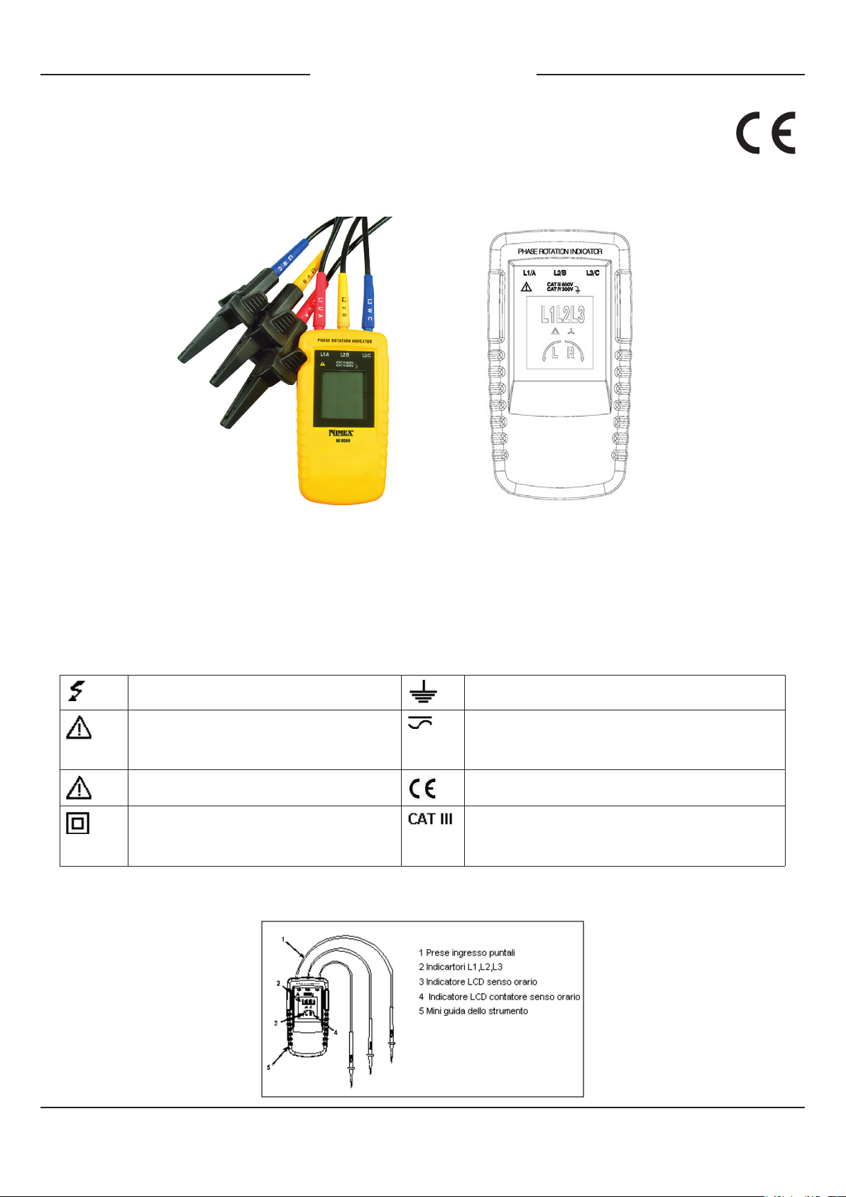
ELEMENTI DELL’INDICATORE DI ROTAZIONE DI FASE
Indicatori, tasti e prese sono mostrati nella gura 1.
Fig. 1Indicatore di rotazione di fase
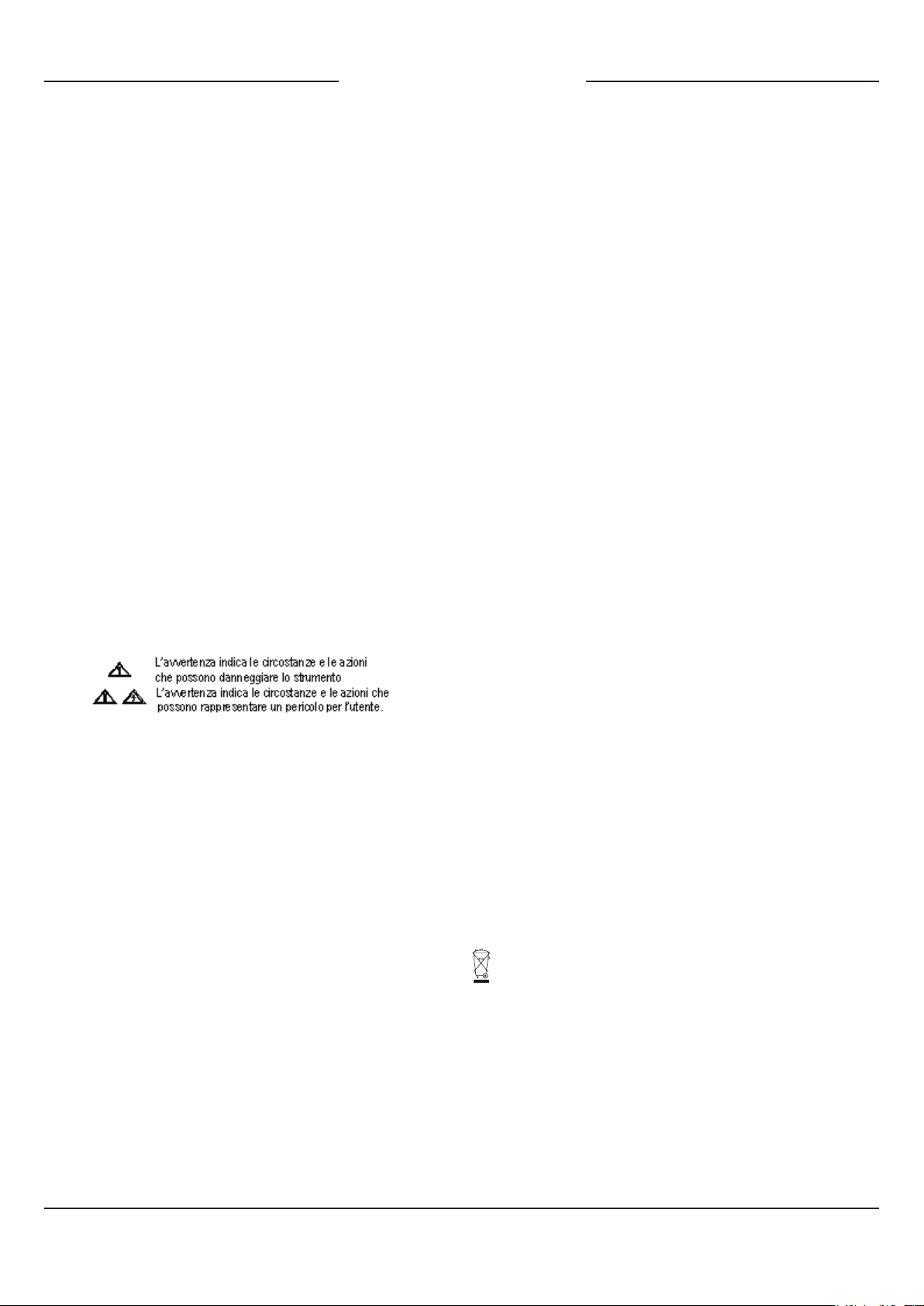
Rischio di scossa elettrica Terra
Rischio di pericolo, per informazioni
importanti consultare il manuale
AC o DC
Tensione pericolosa Conforme alle direttive dell’UE
Apparecchiatura protetta da doppio
isolamento o isolamento di rinforzo
Sovratensione(Installazione)
CATEGORIA III, Grado di inquinamento 2
Per IEC1010-1
Manuale di istruzioni/Scheda tecnica PAGINA 2 DI 4
DETERMINARE IL SENSO DEL CAMPO DI
ROTAZIONE
Per determinare il senso del campo di rotazione:
1. Collegare i puntali all’estremità dei cavi di prova.
2. Collegare i puntali alle tre fasi principali.
3. La luce verde accesa sull’indicatore indica che lo
strumento è pronto per il test.
4. L’indicatore si illumina mostrando il tipo di senso
di rotazione del campo presente: in senso orario o in
senso anti-orario
5. L’indicatore di rotazione si illumina anche quando è
collegato il conduttore neutro N anziché i jacks input
dei puntali .
DISIMBALLAGGIO DELL’INDICATORE DI
ROTAZIONE DI FASE
L’indicatore di rotazione di fase viene consegnato con
i seguenti articoli in dotazione:
1. Tre puntali tipo self-retaining
2. Un clip a coccodrillo
3. Il manuale dell’utente
Se uno di questi articoli risulta danneggiato o
mancante, contattate immediatamente il punto
vendita.
INFORMAZIONI DI SICUREZZA
LEGGETE PRIMA: INFORMAZIONI DI SICUREZZA
Per evitare possibili scosse elettriche o incendi, fate
quanto segue:
Leggete attentamente le seguenti informazioni di
sicurezza prima di usare o servirsi dell’apparecchio
Rispettate i codici di sicurezza locali e nazionali.
Usate le attrezzature per la protezione individuale allo
scopo di evitare scosse elettriche e lesioni.
L’uso dello strumento in modo non conforme a quello
indicato dal produttore può alterare le caratteristiche
di sicurezza / protezione fornite dallo strumento
stesso.
Evitate di lavorare da soli.
Controllate i puntali perché l’isolamento non sia
danneggiato e i li di metallo non siano esposti.
Vericate la continuità dei puntali. I cavi danneggiati
devono essere sostituiti. Non usate l’indicatore di
rotazione se esso sembra danneggiato.
Prestate attenzione quando lavorate con oltre 30V ca
rms, picco di 42V e 60V cc. Tali tensioni elettriche
creano pericolo di scossa.
Quando usate le sonde, tenete le dita lontane dalle
sonde, evitando i contatti. Tenere le dita dietro le
protezioni per le dita sulle sonde.
Le misurazioni possono essere inuenzate
negativamente dalle impedenze di circuiti
supplementari collegati parallelamente o dalle
correnti transitorie.
Vericate il funzionamento prima della misurazione di
tensioni pericolose (tensioni sopra 30V ca rms, 42V e
60V cc).
Non usate l’indicatore di rotazione mancante di una
delle sue parti.
Non usate l’indicatore di rotazione in un ambiente
umido.
SPECIFICHE AMBIENTALI
Temperature di funzionamento: da 0°C a + 40°C
Grado di inquinamento: 2
Tipo di protezione: IP 40
SPECIFICHE MECCANICHE
Dimensioni (H x W x D): 130mm x 69mm x 32mm
Peso: 130g
SPECIFICHE DI SICUREZZA
Sicurezza elettrica
IEC 61010/EN61010
IEC 61557 – 7/EN 61557 – 7
Tensione massima di funzionamento : (Ume) 690V
Livelli di protezione: CAT III, 600V a terra
SPECIFICHE ELETTRICHE
Alimentazione
Dall’unità in prova
Determina il senso del campo di rotazione
Tensione nominale: da 40 a 690VCA
Gamma di frequenza(fn): da 15 a 400HZ
Assorbimento: 1 mA
Corrente nominale di prova (per fase): 1 mA
Informazioni agli utenti
Il simbolo riportato sull’apparecchiatura indica che il riuto deve essere oggetto di
“raccolta separata”. Pertanto, l’utente dovrà conferire (o far conferire) il riuto ai
centri di raccolta differenziata predisposti dalle amministrazioni comunali, oppure
consegnarlo al rivenditore contro acquisto di una nuova apparecchiatura di tipo
equivalente. La raccolta differenziata del riuto e le successive operazioni di
trattamento, recupero e smaltimento favoriscono la produzione di apparecchiature
con materiali riciclati e limitano gli effetti negativi sull’ambiente e sulla salute
eventualmente causati da una gestione impropria del riuto. Lo smaltimento
abusivo del prodotto da parte dell’utente comporta l’applicazione delle sanzioni
amministrative di cui l’articolo 50 e seguenti del D. Lgs. N° 22/1997.

Manuale di istruzioni/Scheda tecnica PAGINA 3 DI 4
PHASE ROTATION INDICATOR
ART. 9/12020 NI 8060
INSTRUCTION MANUAL
INTRODUCTION
The phase rotation indicator is a handheld instrument designed to detect the rotary eld of three-phase
systems.
SYMBOLS
The following symbols appear on the phase Rotation indicator or in this manual.
Table 1. Symbols
ELEMENTS OF THE PHASE ROTATION INDICATOR
Indicators, buttons, and jacks are shown in Figure 1.
Figure 1. The phase Rotation Indicator
Risk of electric shock Earth
Risk of Danger. Important
information see manual
AC or DC
Hazardous Voltage Conforms to E directives
Equipment protected
by double or reinforced
insulation
Overvoltage (installation)
Category III, Pollution Degree 2 per IEC 1010-1 refers
to the level of impulse wishstand voltage protection
provided. Equipment of OVERVOLTAGE CATEGORY III is
equipment in xed installations (e.g., electricity meter and
primary over-current protection equipment.)

Manuale di istruzioni/Scheda tecnica PAGINA 4 DI 4
DETERMINE THE ROTARY FIELD DIRECTION
To determine the rotary eld direction:
1. Connect the test probes to the end of the test
leads.
2. Connect the test probes to the three mains phases.
3. The green ON indicator shows that the instrument
is ready for testing.
4. Either the clockwise or counter-clockwise rotary
indicator illuminates showing the type of rotary eld
direction present.
5. The rotary indicator lights even if the neutral
conductor, N, is connected instead of the Test lead
input jacks.
UNPACKING THE PHASE ROTATION INDICATOR
The phase Rotation indicator ships with the following
items:
- 3 pieces self-retaining test probes
- Alligator clip
- Users Manual
If an item is damaged or missing, contact the place of
purchase immediately.
INFORMAZIONI DI SICUREZZA
READ FIRST: SAFETY INFORMATION
To avoid possible electric shock or re, do the
following:
Read the following safety information carefully before
using or servicing the instrument.
Adhere to local and national safety codes.
Individual protective equipment must be used to
prevent shock and injury.
Use of instrument in a manner not specied by the
manufacturer may impair safety features/protection
provided by the equipment.
Avoid working alone.
Inspect the test leads for damaged insulation or
exposed metal. Check test lead continuity. Damage
leads must be replaced. Do not use the phase
Rotation indicator if it looks damaged.
Be careful when working above 30V ac rms, 42V
ac peak and 60V dc. Such voltages pose a shock
hazard.
When using the probes, keep ngers away from
probe contacts. Keep ngers behind the nger guards
on the probes.
Measurements can be adversely affected by
impedances of additional operating circuits connected
in parallel or by transient currents.
Verify operation prior to measuring hazardous
voltages (voltages above 30V ac rms, 42V ac peak
and 60V dc).
Do not use the phase Rotation indicator with any of
the parts removed.
Do not use the phase Rotation indicator around
explosive gas, vapor, or dust.
Do not use the phase Rotation indicator in a wet
environment.
SPECIFICATIONS ENVIRONMENTAL
Operating Temperature
0°C to +40°C
Pollution Degree 2
Type of protection IP 40
MECHANICAL SPECIFICATIONS
Size (H x W x D): 130mm x 69mm x 32mm.
Weight: 130g
SAFETY SPECIFICATIONS
Electrical Safety
IEC 61010/EN61010,
IEC 61557-7/EN 61557-7
Maximum Operating Voltage (Ume) 690 V
Protection Levels
CAT lll, 600V to ground
ELECTRICAL SPECIFICATIONS
Power Supply
From unit under test
Determine Rotary Field Direction
Nominal Voltage
40 to 690 VAC
Frequency Range (fn)
15 to 400HZ
Current pickup 1 mA
Nominal Test current (in per phase) 1 mA
Information for users:
The symbol on the equipment indicates that the waste must be “separately
collected”. Therefore, the user must carry (or have it carried) the waste to the
separately collected waste centers set up by local governments, or deliver it to
the dealer against purchase of a new equivalent-type equipment. The separate
waste collection and the subsequent processing, recovery and disposal
operations favour the production of equipment with recycled materials and limit
the negative effects on the environment and on health which may be possibly
caused by the waste improper management. The improper product disposal by
the user causes the application of administrative sanctions according to the Art.
50 et. seq. of the Law Decree No. 22/1997.
Table of contents
Languages:


