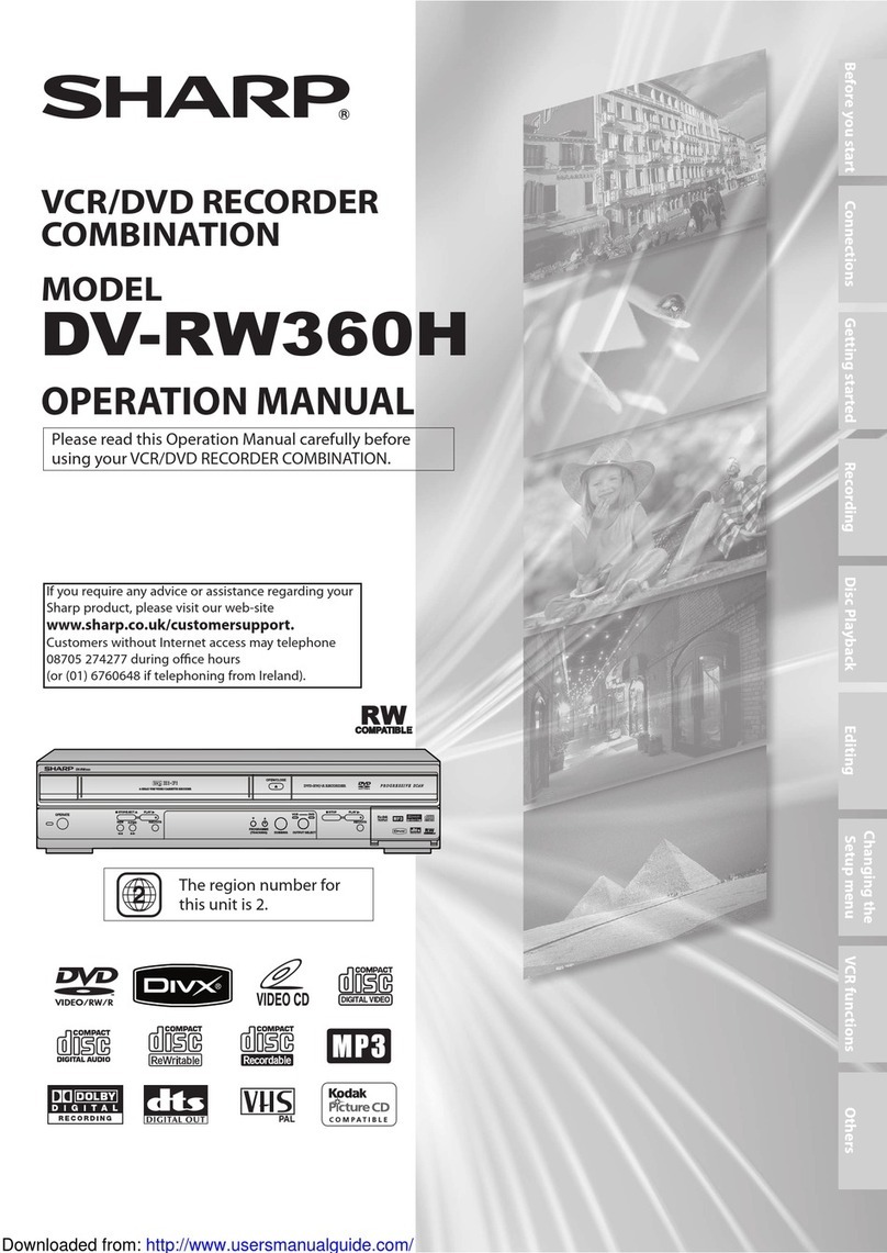
Sharp SYSTEM-CD555ZT(GY) User manual

SHARP
SERVICEMANUAL
S$3410SYSCD555
SYSTEM-CD555ZT(GY)
COMPACT
IS
¢
Inthe
interests
of
user-safety
the
set
should
be
restored
to
its
original
|
DIGITAL
AUDIO
condition
and
only
parts
identical
to
those
specified
be
used.
TROUBLESHOOTING
(CD
SECTION)
FUNCTION
TABLE
OF
UG
cscs
cissnsecitacd
ansctessiocbaiscespencscahansideece
Rahecdicadae
soa
cucdlies,
Std
te:
EAPEODED
Vi
ssc
eicsscedsiciuceussishovardsceass
satids
ouecconctady
casbuneben.
Soastaslaiaetstac
sess
eosececglocéoscd
i
SHARP
CORPORATION

-SYSTEM-CD555ZT
|
FOR
A
COMPLETE
DESCRIPTION
OF
THE
OPERATION
OF
THIS
UNIT,
PLEASE
REFER
|
i
TO
THE
OPERATION
MANUAL.
@
General
3
Power
source:
Power
consumption:
Output
power:
Output
terminal:
Dimensions:
Weight:
@
Tuner
section
Frequency
range:
@
Tape
deck
section
Frequency
response:
Signal/noise
ratio:
Wow
and
flutter:
Motor:
Bias
system:
Erase
system:
SPECIFICATIONS
AC
220
-
230
V,
50
Hz
DC
12
V[“D’
size
(UM/SUM-1,
R20
or
HP-2)
battery
x
8]
55W
PMPO;
46
W
(23
W
+
23
W)
(AC
operation)
MPO;
14
W(7W+7
W)
(AC
operation)
RMS;
10
W
(5
W
+5
W)
(DC
operation,
10
%
T.H.D.)
Headphones;
16
-
50
ohms
(recommended;
32
ohms)
3.5
mm
(1/8")
socket
CD
out;
0.5
V/10
kohms
RCA
pin
type
Width;
294
mm
(11-9/16"
)
Height;
269
mm
(10-9/16")
Depth;
229
mm
(9")
3.9
kg
(8.6
ibs.)
without
batteries
FM;
64
-
108
MHz
LW;
148.5
-
283.5
MHz
MW;
526.5
-
1,606.5
kHz
SW;
5.95
-
18
MHz
50
-
14,000
Hz
(Normal
tape)
55
dB
(TAPE
1,
playback)
50
dB
(TAPE
2,
recording/playback)
0.25%
(WRMS)
DC
12
V
electric
governor
(1motor)
AC
bias
AC
erase
STRINGING
1.
Turn
the
drum
fully
in
the
direction
®
shown
in
Fig.
2-2
and
Stretch
its
cord
over
the
parts
in
the
numerical
order.
2.
Then
turn
the
tuning
control
shaft
fully
in
the
direction
@
shown
in
Fig.
2-2
and
fix
its
pointer
as
shown
in
Fig.
2-1.
Dial
Pointer
(222)
Figure
2-1
@
Compact
disc
player
section
Dise:
Compact
disc
Signal
readout:
Non-contact,
3-beam
semi-conductor
laser
pickup
Audio
channels:
2
Decoder:
16-bit
linear
quantization
Filter:
4-times
oversampling
16-bit
digital
filter
Frequency
response:
20
-
20,000
Hz
Dynamic
range:
90
dB
Wow
and
flutter:
Unmeasurable
(less
than
0.001%
W.
peak)
@
Speaker
section
Type:
2-way
bass-reflex
type
Speakers:
12
cm
(4-3/4")
free-edge
woofer
x
2
Maximum
input
13W
power:
Dimensions:
Width;
170
mm
(6-5/8”
)
Height;
261
mm
(10-1/4")
Depth;
190
mm
(7-7/16")
Weight:
1.5
kg
(3.3
Ibs.)
/each
poate
;
=]
|
Specifications
for
this
model
are
subject
to
change
without
prior
|
notice.
Sh
Se
ey
See
Pee
eee
a
Ee
oer
OF
DIAL
CORD
Drum
:
|
422mm
|
(223)
Figure
2-2

@
CD
display
section
1.
Piay
Indicator:
p>
2.
Track
Number
Indicator
3.
Random
Indicator
4.
Minutes
and
Seconds
indicator
5.
Memory
Indicator:
M
6.
Pause
Indicator:
11
7.
Programme
Indicator:
P
8.
Repeat
indicator:
<
@
CD
section
§.
CD
Compartment
10.
CD
Eject
Button:
«
11.
Clear
Button
12.
Random
Button
13.
Call
Button
14.
Memory
Button
15.
Stop
Button:
m
16.
Play/Repeat
Button:
»
17.
Track
Up/Cue
Button:
ppi/>p>
18.
Track
Down/Review
Button:
w«/<<
19.
Pause
Button:
11
®@
Amplifier
section
20.
Graphic
Equalizer
Controls
21.
Extra
Bass
Control:
X-BASS
22.
Power/Function
Switch
:23.
Power/TAPE
1
Direction
indicators
24.
Volume
Control
@
Tuner
section
25.
FM
Mode/Tape
Selector
Switch
26.
FM
Stereo
Indicator
27.
Band
Selector
Switch
28.
Tuning
Control
SYSTEM-CD555Z
Tr
Ur
c=K=Te))
(CE
Ceo
S>—-
25
26
27
28

@
Tape
section
1.
Dubbing
Speed
Switch
2.
FM
Mode/Tape
Selector
Switch
3.
Power/TAPE
1
Direction
Indicators
TAPE
2
|
4.
Record
Button:
@
5.
Play
Button:
>
6.
Rewind
Button:
<<
7.
Fast
Forward
Button:
>>
8.
Stop/Eject
Button:
Ba
9.
Pause
Button:
II
TAPE
1
|
10.
Reverse
Mode
Switch:
po/.>
11.
Play
Button:
<>
12.
Fast
Wind
Buttons:
<<>>
13.
Stop/Eject
Button:
mya
14.
Direction
Switch:
«<p>
@
Rear
panel
15.
FM/SW
Telescopic
Rod
Aerial
16.
Left
Speaker
Release
Lever
17.
Beat
Cancel
Switch
18.
Headphones
Socket
19.
Speaker
Terminals
20.
CD
Output
Sockets
21.
Right
Speaker
Release
Lever
22.
AC
Power
Input
Socket
23.
Battery
Compartment
@
Speaker
section
24.
Tweeter
25.
Woofer
26.
Bass
Reflex
Port
27.
Speaker
Wires
(GaananManaenel
456
7
8
91011121314

SYSTEM-CD5552T
SYSTEM-CD555ZT
DISASSEMBLY
——
Caution
on
Disassembly
|
My)
x5
Follow
the
below-mentioned
notes
when
disassembling
the
|
(Al)
x2
3x.G5mm
unit
and
reassembling
it,
to
keep
its
safety
and
excellent
|
$3x
12mm
¢
|
performance:
|
-
1.
Take
cassette
tape
and
compact
disc
out
of
the
unit.
i
:
2.
Be
sure
to
remove
the
power
supply
plug
from
the
wall
outlet
before
starting
to
disassemble
the
unit
and
remove
|
the
batteries
from
the
unit.
3.
Take
off
nylon
bands
or
wire
holders
where
they
need
be
|
removed
when
disassembling
the
unit.
After
servicing
the
|
unit,
be
sure
to
rearrange
the
leads
where
they
were
before
-
disassembling.
|
4.
Take
sufficientcare
on
static
electricity
of
integrated
circuits
|
and
other
circuits
when
servicing.
Rear
Cabinet
(H1)
x14
LCD
PWB
$3
x
10mm
Top
Cabinet
Figure
6-1
REMOVAL
Rear
Cabinet
(G2)x
4
?3
x
10mm
Graphic
EQ.
PWB
sdbeeiauateeetahes
(B1)x4
TID
saitenkteniecsane
(B2)x1
.
Socket
/
Flat
Wire
...(B3)x2
Top
Cabinet
(H2)
x
1
Figure
6-3
Main
PWB
(with
Tuner
Frame)
(F1)
x2
&
(B1)
x2
.
$3
x
10mm
$3
x
12mm
Volume
PWB
Main
PWB
Front
Cabinet
Graphic
EQ.
Front
Cabinet
Figure
6-2
7
fi
0
=
a
B1)x2
O3
x2
Switch
PWB
(B3)
x1
CD
Servo
PWB
:
:
Figure
5-2
CD
Mechanism
‘
Volume
CD
Servo
SPEAKER
PWB
PWB
EMOVAL
Top
Cabinet
Front
Cabinet
Front
Cabinet
(D3)
x1
(D2)
x
4
Sr
(D4)
x7
D1
©
$3
x
10mm
Ga.
tunes
Figure
5-3

REMOVING
AND
REINSTALLING
THE
MAIN
PARTS»
TAPE
MECHANISM
SECTION
Perform
steps
1,
2,
3
and
4
of
the
disassembly
method
to
remove
the
tape
mechanism.
How
to
remove
the
record
/
playback
and
erase
heads
(TAPE
2)
(See
Fig.
7-1.)
.
1.
Remove
the
2
screws
(A1)
to
remove
the
button
frame.
2.
Remove
the
2
screws
(A2)
to
remove
the
record/playback
head.
3.
Remove
the
2
screws
(A3)
to
remove
the
erase
head.
Note:
After
replacing
the
heads
and
performing
the
azimuth
adjustment,
be
sure
to
apply
screwlock.
How
to
remove
the
playback
head(TAPE1)
(See
Fig.
7-2.)
1.
Remove
the
2
screws
(B1)
to
remove
the
button
frame.
2.
Remove
the
2
screws
(B2)
to
remove
the
playback
head.
Note:
1.
The
playback
head
of
this
mechanism
is
supplied
as
finished
product
with
flexible
PWB.
Before
removing
the
flexible
PWB,
remove
the
solder
on
the
switch.
2.
After
replacing
the
head
and
performing
the
azimuth
adjust-
ment,
be
sure
to
apply
screwlock.
How
to
remove
the
pinch
roller(TAPE
2)
(See
Fig.
7-3.)
1.
Carefully
bend
the
pinch
roller
hook
in
the
direction
of
A,
and
remove
the
pinch
roller
(C1)
upwards.
How
to
remove
the
pinch
roller(TAPE1)
(See
Fig.
7-3.)
1.
Remove
the
stop
washer(D1)
with
a
small
precision
screwdriver
and
extract
the
pinch
roller.
2.
To
remove
the
left
pinch
roller,
use
the
same
procedure.
Note:
If
the
stop
washer
is
deformed
or
damaged,
replace
it
with
a
new
one.
(Al)xl
(Ai)x!
i
,
Button
Frame
Erase
Rec/P.B
Head
Head
i!
(A2)x!
S2x7mmM
(A2)xI
“
$2x3mm
(A3)x2
=
se
ae
Lp
Sapes
husk
we
eee:
aS
2a
Erase
Washer
=
Head
Azimuth
—
Flywheel
Spring
Spring
Figure
7-1
Button
(Bidx!
62x9mm
J
822
G2x4.5mm
Fiexibie
PwB
+
|
Flywheel
Figure
7-2
(C1)
Pinch
Roller
Pinch
Roller
~~»
°
°o
~&
(DI)x!
Stop
Washer
Figure
7-3
SYSTEM-CD555ZT
SYSTEM-CD5552T
How
to
remove
the
belt
(See
Fig.
8-1.)
1.
Remove
the
tape
2
main
belt
(E1)
from
the
motor
side.
2.
Remove
the
FF/REW
belt(E2).
3.
Remove
the
tape
1
main
belt
(F1)
from
the
motor
side.
How
to
remove
the
motor
(See
Fig.
8-2.)
1.
Remove
the
2
screw
(J1)
to
remove
the
tape
2
mechanism.
2.
Remove
the
3
screws
(J2)
to
remove
the
motor.
CD
MECHANISM
SECTION
Perform
steps
1,
2, 8,
9
and
10
of
the
disassembly
method
to
remove
the
CD
mechanism.
Removing
the
optical
pickup
(See
Fig.
8-3.)
1.
Remove
4
pawls
(A1)
and
remove
cover
(A2).
2.
Remove
4
screws
(A3)
and
remove
2
shafts
(A4).
(FI)
Main
Belt
Figure
8-1
(J2)x3
K>
Special
Screw
(A3)
x2
$2.6
x
8mm
Figure
8-3

SYSTEM-CD555ZT
ADJUSTMENT
MECHANISM
SECTION
e
Driving
Force
Check
Torque
Meter
Play:
TW-2412
Reverse
play:
TW-2422
Over
60g
e
Torque
Check
Torque
Meter
Specified
Value
Play:
TW-2114
30
to
60
g.cm
30
to
60
g.cm
Fast
forward:
55
to
120
g.cm
55to
120g.cm
TW-2231
Rewind:
TW-2231
55
to
120
g.cm
55
to
120
g.cm
e
Head
Azimuth
MTT-114
e
Tape
Speed
InstrumentConnection
Headphones
Jack
(Load
resistance:
32
ohms)
Test
Tape|
Adjusting
|
Specified
Value
instrument
Point
Connection
Headphones
Jack
(Load
resistance:
32
ohms)
MTT-111
|
VR401
3,000
+
90Hz
TAPE
SECTION
Position
of
each
switch
or
control
Beat
cancel
switch
Graphic
equalizer/X-Bass
Dubbing
speed
e
Bias
Oscillation
Check
Specified
Vaiue
A:
80
+
4
kHz
B:
+4+
1
kHz
forA
C:
+6
+
1
kHz
forA
Beat
cancel
e
Erase
Current
Check
es
Resistor
for
measurement:
1
ohm
e
Playback
Amplifier
Sensitivity
Check
Speaker
Terminal
(Load
resistance:
3
ohms)
Specified
Value
MTT-118
1.0V+3dB
SYSTEM-CD555ZT
TUNER
SECTION
fL:
Low-range
frequency
fH:
High-range
frequency
e
FM
IF/RF
Test
Stage
Specified
Value/
Adjusting
Point
Band
Coverage!
fL:
L2
fH:
TC2
64.0
MHz:
L1
94.0
MHz:
TC1
Instrument
Connection
Input:
Antenna
Output:
Pin
9
of
IC2
\
{
|
4
Tracking
e
VCO
Frequency
Adjusting
instrument
Connection
Point
VR1
38
KHz
+
100
Hz
Specified
Value
Pin
6
of
IC3
\
Adda
resistor(10
kohm)
between
pin
7
of
C3
and
ground,and
adjust
Note:
in
stereo
state.
e
AM
IF/RF
Test
Stage
Specified
Value/
Instrument
Connection
Adjusting
Point
F
LW
Band
fL:
L6
Coverage
fH:
TC6
LW
Tracking
|
170
kHz:
L3(LW)
270
kHz:
TC7
fL:
L5
fH:
TC4
600
kHz:
L3(MW)
1,400
kHz:
TC3
SW
Band
fL:
L7
Coverage
fH:
TC8
SW
Tracking
|
6.5
MHz:
L4
16
MHz:
TC5
Input:
Antenna
Output:
Pin
5
of
IC2
Input:
Antenna
Output:
Pin
9
of
IC2
MW
Band
Coverage
MW
Tracking
SPEAKERS
BEAT
aie
a
CANCEL
Prones
“8
©
3
NALW
Bae
‘ON
'
MES
ao
mA
TRACKING
iF
7
ft
FM
BAND
|
r+
|
COVERAGE
I
13
[tH]
HPS
TT
Tae
ree
ts
2a
r
tt,
LZ
T2
Tai
BAND
=
i5[(@]|@
13
:
i
coverace
[nt
—1-
=
Te45
tc
2
wa
1C2
[fH]
FM
z
C3
Ob
tc;
TRACK
ING
Eee
apm
or
=
R/P_SW
-
[
—s
ee
(Q)"
{Fu
F]
ees
ee
7]
VR401
Lw
SPEED
MAIN
PWB-A1
:
Figure
10
ADJUSTMENT
POINTS
-10=

SYSTEM-CD555ZT
CD
SECTION
"Track
skipping
and/or
no
TDC(Table
Of
Contents)
may
be
caused
by
a
build
up
of
dust
other
foreign
matter
on
the
laser
pickup
lens.
Before
attempting
any
adjustment
make
certain
that
the
lens
is
clean.
If
not,
clean
it
as
mentioned
below.”
1.
Turn
the
power
off.
2.
Gently
clean
the
lens
with
a
lens
cleaning
tissue
and
a
small
amount
of
isopropyl
alcohol.
Note:
Do
not
touch
the
lens
with
the
bare
hand.
1.
Preparation
for
Adjustment
Setting
the
Test
Mode
TEST
MODE
0
Pressing
simultaneously
the
All
the
segments
light
for
1.5
“CLEAR”
and
“CALL”
buttons,
set
|
seconds
and
then
the
Test
Mode
the
function
switch
to
“CD”.
0
indication
appears.
“|
F
=
=]
TEST
MODE
1
TEST
MODE
2
TEST
MODE
3
TEST
MODE
4
TEST
MODE
5
After
TEST
MODE
5
the
PLAY
button
is
inoperative.
Even
when
it
is
pressed
(6th
time),
key
entry
is
not
accepted.
In
TEST
MODE
0
press
once
the
PLAY
button.
(1st)
Laser
lights.
In
TEST
MODE
1
press
once
the
PLAY
button.
(2nd)
Focus
start
(Servo
ON)
Disc
rotates.
(Spin
servo
ON)
(Use
the
disc.)
In
TEST
MODE
2
press
once
the
PLAY
button.
(3rd)
In
TEST
MODE
3
press
once
the
PLAY
button.
(4th)
Tracking
servo
ON
(Use
the
disc.)
Track
No.
and
time
are
indicated.
(Use
the
disc.)
In
TEST
MODE
4
press
once
the
PLAY
button.
(5th)
*Unless
the
CD
lid
switch
SW961
is
tumed
on,
the
test
mode
is
not
set.
Button
Operation
in
Test
Mode
14.
When
the
STOP
button
is
pressed,
all
operations
stop.
At
this
time
the
optical
pickup
does
not
slide,
and
TEST
MODE
0
is
displayed.
2.
While
the
UP/CUE(DOWN/REVIEW)
button
is
pressed,
the
optical
head
moves
from
inside
to
outside
or
from
the
outside
to
the
inside.
*
Operation
is
possible
both
during
playing
and
stopping.
e
While
this
operation
is
executed,
the
TEST
MODE
indication
does
not
change.
After
the
optical
pickup
is
slided
from
the
outside
to
the
inside
and
the
optical
pickup
switch
is
turned
on,
the
slide
stops.
(At
the
same
time
TEST
MODE
Ois
set.)
Notes:
1.
Any
buttons
other
than
those
specified
above
are
invalid.
2.
Before
operation
be
sure
to
connect
all
the
connectors.
442
SYSTEM-CD5552ZT
Servo
Unit
All
the
semivariable
resistors
must
be
set
in
the
mechanical
center
position.
Adjusting
Parts
Instrument
Connection
i
Set
TEST
MODE
0,
and
move
the
pickup
to
the
center
i
Set
Test
MODE
1
(make
sure
that
the
laser
lamp
lights)
After
loading
a
disc,
set
to
TEST
MODE
2.
(Check
to
see
that
focus
servo
is
ON.:
The
disc
does
not
rotate,
and
a
whining
sound
is
heard.)
Set
TEST
MODE
3
(Spin
servo
is
turned
on,,
and
the
disc
rotates)
i
|
i
Tracking
error
balance
adj.
NVRA1
*4
(See
Fig.
12-1)
Pin
6
(1/2Vcc)
and
pin
4
(TG1)
of
TP751
Set
TEST
MODE
4
(Tracking
servo
is
turned
on.)
|
Check
the
HF
signal
waveform
_
Amplitude
of
1.5-2.0
Vp-p
|
Pin
3
(HF)
and
pin
7
(GND)
of
'
|
(See
Fig.
12-2.)
|
TP751
Focus
gain
adj.
VR751
Adjust
to
obtain
the
same
waveform
|
Pin
1
(FG1)
and
pin
5
(FG2)
of
|
on
CH1
and
CH2.
*2
TP751
and
ground
(The
relay
circuit
|
is
used.)
|
Adjust
to
obtain
the
same
waveform
|
Pin
4
(TG1)
and
pin
2
(TG2)
of
i
|
Tracking
gain
adj.
VR750
on
CH1
and
CH2.
*3
TP751
and
ground
(The
relay
circuit
|
is
used.)
Check
again
the
HF
signal
waveform.
'
Set
TEST
MODE
5,
and
make
sure
that
track
No.
and
time
are
displayed.
Stick
black
tape
on
the
disc,
and
play
that
section
(Fig.
13-1).
(Any
mode
other
than
the
test
mode
is
acceptable.)
E28.
Focus
offset
adj.
VR700
*4
(Fig.
13-2)
Pin
6
(1/2Vcc)
and
pin
1
(FG1)
of
:
TP751
*5
Tracking
offset
adj.
VR710
Pin
6
(1/2Vcc)
and
pin
4
(TG1)
of
TP751
*7
*
4.
Adjust
to
obtain
vertically
symmetrical
waveform
(Fig.
12-1)
with
respect
to
reference
DC
level.
The
reference
level
is
1/2Vcc.
(Amplitude
of
0.5
to
1.5
Vpp)
*
2.
Input
oscillation
frequency:
1.3
kHz,
100
mV
rms
*
3.
Input
oscillation
frequency:
1.5
kHz,
300
mV
rms
*
4.
Watch
the
monitor.
Adjust
so
that
the
error
waveform
is
uniform
and
minimum
(Fig.
13-2)
and
the
audio
output
is
played
properly
without
noise
(track
jump
noise)
and
free
from
skips
and
pauses.
*
5.
The
appropriate
measuring
range
of
the
oscilloscope
is
50mV
and
0.5mS.
Connect
the
trigger
to
pin
14
(HFOK)
of
CNS700.
Trigger
the
coupling
at
DC
and
(—)
slope.
Observe
the
waveform
in
the
normal
trigger
mode.
*
6.
Watch
the
monitor.
Adjust
so
that
the
error
waveform
is
uniform
and
minimum
(Fig.
13-2)
and
the
audio
output
is
played
properly
without
noise
(track
jump
noise).
*
7.
The
appropriate
measuring
range
of
the
oscilloscope
is
0.1V
and
0.5mS.
The
trigger
is
the
same
as
*5.
(Reference)
When
the
noise
element
of
the
error
waveform
is
large
and
unclear,
observe
the
waveform
through
the
low-pass
filter
(Fig.
13-3).
|
SSR
RER
MANNS
DL
ARR
RARRRA
OP.
O.O
OP OP
OG.
AK
,
Vp-p
Reference
FarERETUTNINA
Mm
|
Syma
evel
—
AT
ALLARERARV
A
uP
anc
down
1/2
Vec
et
ee
—0.5~1.5Vp-p
ms
verter
deed
Pin
7
Figure
12-1
Figure
12-2
2405

SYSTEM-CD555ZT
SYSTEM-CD555ZT
Stick
black
tape
on
the
disc
:
NOTES
ON
SCHEMATIC
DIAG
RAM
(1.2
~
1.5
mm
wide)
¢
Resistor:
1.
Tuner
aa
To
differentiate
the
units
of
resistors,
such
symbol
as
K
and
M
are
(.
):
AM
mode
/
|
used:
the
symbol
K
means
1000
ohm
and
the
symbol
M
means
Marking
except
for
(_
):
FM
mode
,
g
{
\
1000
kohm
and
the
resistor
without
any
symbol
is
ohm-type
2.
CD
i
C)
i
resistor.
Besides,
the
one
with
“Fusibie”
is
a
fuse
type.
(_
):
Play
mode
\
|
¢
Capacitor:
Marking
except
for(
):
Stop
satate
\
/
+
ge
. . .
eee
<a
.
/
|
erect
Oscilloscope
To
indicate
the
unit
of
capacitor,
a
symbol
P
is
used:
this
3.
eueo
Sel
FG1
Q
;
5
symbol
P
means
micro-micro-farad
and
the
unit
of
the
capacitor
(
):
Record
mode
TG1
without
such
a
symbol
is
microfarad.
As
to
electrolytic
capacitor,
Marking
except
for(
):
Play
mode
A
disc
other
than
the
test
disc
The
error
waveform
should
be
=
820P
the
expression
“capacitance/withstand
voltage”
is
used.
can
be
used.
Do
not
put
the
black
uniform
and
minimum.
(CH),
(TH),
(RH),
(UJ):
Temperature
compensation
*
Schematic
diagram
and
Wiring
Side
of
P.W.
Board
for
this
tape
on
the
initialized
section
o
(ML):
Mylar
type
model
are
subject
to
change
for
improvement
without
prior
(TOC).
1/2
VCC
(P.P):
Polypropylene
type
notice.
Figure
13-1
Figure
13-2
Figure
13-3
¢
The
indicated
voltage
in
each
section
is
the
one
measured
by
e
Parts
marked
with
“A\”
(<==)
are
important
for
maintaining
;
Digital
Multimeter
between
such
a
section
and
the
chassis
with
nc
the
safety
of
the
set.
Be
sure
to
replace
these
parts
with
gs
signal given.
specified
ones
for
maintaining
the
safety
and
performance
of
TP751
pada
the
set.
(FG1)
(TG1)
Hisie
~)
GENERATOR
(FG2)
oe
oe
mee
RP
SELECTOR
pPLAYEPEAT
[OFF
Sotilator
ue
a
Koni
RIP
SELECTOR
PLAY
PLAY/REPEAT
OFF
DUBBING
SPEED
NORMAL
The
jig
(BPF)
we
recommended
to
reduce
high
frequency
TAPE
SELECTOR/FM
MODE
|
NORMAL/FM
NONO
UP/CUEPp}
ee
ee
BEAT
CANCEL
ares
DOWNAEVIEWbes
tors
can
be
used
to
achieve
the
same
results.
OFF
A
OFF
|
TAPE
2
STOP
TAPE
1
PLAY
Figure
13-4
Figure
13-5
Rex
Do
not
connect
the
cable
on
the
pickup
in
the
power
ON
state.
This
may
damage
thw
pickup.
FRONT
FRONT
CNP720
CFS700
TP751
ald
(39s
(sec
:
VR750
:
TOP
TOP
a5
lta
il
ll
see
hee
|
ge,
bacco»
SAIN
(ae
S585)
.
(1900)
meq
va7siL_HEgars|
(79¢39
(3)
ce
ci
2
2SC1740
SR
2S02061
F
DTC144
EK
2SA1235
FG
vrrio[
ees]
2862001
K
OTC114.
TK
cm
=
ered
es
grataa
ee
FOCU!
A
Clee]
DTA114
ES
DTA114
EK
VR700
DTC144
Ss
2SD468
C
FOR
LASER
POWER
DTC114
YS
NOT
ADJUSTMENT
:
CNP951
1
|
FRONT
TOP
VIEW
1C780
PICKUP
aly
jew
FOR
DEFOCUS
—>k
NOT
ADJUSTMENT
|
f
TRACKING
ERROR
BALANCE
SLR34VR3
DA118
Figure
13-6
ADJUSTMENT
POINTS
Figure
14
TYPES
OF
TRANSISTOR
-13-
;
-14-

SYSTEM-CD555ZT
SYSTEM-CD555zT
~
SERVO
+5¥
VRTI0
TRACKING
OFPSET
1c750
MS1594AFP
SERVO
CONTROL
SERVO
+5V
oe
PICKUP
UNIT;
MS
1598FP
~
ALS
PRE
AMP.
Se
OPPSET
30K
ne
200K
org
a3
‘
‘
i
e700
H
Y
BP
I-v
eS
5
i
}
chack
ang
:
i)
[
BAL.
2°
H
rae
/FOCUS
DRIVER
i
exc
:
ie
:
jp
ere
:
Y
een
ay,
>
:
i
A
rocus
coi,
}
to.
Vero
I;
"
tty
i
ep
|
H
2
OY
Hy
rguaml
|
:
=i
i
a
a
an
!
i
wb
i
aby
I
i
reste
1
i
wvat
88
i
{TRACKING
J
if
i |
ERROR
I
Y
i
[“
j
BALANCE
Y
H
}
eae
|
,
H
;
i
H
LASER
LD
DRIVER
ND
AUTOMATIC
LASER
POWER
CONTROL
y
,
4
4
}
;
;
CPGND
Wet
FSRi
SW12.
Seay
3
12.
5eA
tr
UK
¢
Y
4
Y
y
;
OHH
PEEL
ILEL
IT
IZLE
ELIEELILEATELILA
W
Xs
Ce
ae
a
a
a
as
(aa
ee
ee
ae
LCD
PWB
|
=)
i
oY
iam
t
cro
}
Y
SERVO
+5V¥
VJLLL
LL
2
dh
LL
2
LL
LB
uesoser
SWss1-s¥958
y)
)
aecazae
tr
MaNOAY,
paw
i|
7
4
CD
SIGNAL
CONTROL
f
fig
oY
rly
oY
Le
|W
ae
2]
lig
f
g
:
Y
ig
y
ices!
_/
MICROCOMPUTER
LAA
TSN
SANAS
SAN
SAAASANSSANNAA
=a
a
pendent
poor
é
Lal
A
A»
CDA
ALL
hirkgh
hh
heheheh
co
LID
OPEN/CLOSE
Ane
nan
d
eae
aden
nme
Renee
eneedesnnenwnneneen
Enel
meee
Re en
enee
tema
eneeennvames
sane
seamaneUaneennenenaeneneneen
WIZLLLLLALLLAE
LDL
LL
LLL
LLL
LLL
DLL
Ld
cD
MUTE
Garay
©
By
out
TO
MAIN
SECTION
cD
SYNC
IN
Figure
15
BLOCK
DIAGRAM
(1/2)
S755
ase:
VV
1c720
272D
SLIDE
MOTOR
RIVER
aS
out:
I
4
Ni
ape
(3)
Tonk
bit?
ES
i
in2-
?
]
&)
{
g
SLIDE
MOTOR
M701
.s)
C)
6
SERVO
+7.
4V
©
SPIN
MOTOR
-—__—_——
M
)
MTIOZz
CNPS81
SERVO+SV
DIGITAL
_GND
eo
16721
L272
SERVO
dh
pene
ty
AUDIO
+7.
éV¥
2)
audio
_anp
{>|
<>
[cxsees]
Loe
I}
TO
MAIN
SECTION
a-ch
a
SWITCHING
D/A
cauyarras
TDAI311T
©)
=
=
foe
&)
>
7
&
es
aE
i
PAR!
source
216

1c3
TA7343AP
ROD
ANTENNA
oO
G)
4
BAND
SELECTOR
=]
PLL
FM
MPX
=
te
i
STERLO
gece
Ee
ererer,
|
|
x
CONSTANT!
VOLTAGE
DECODER
TA8110AP
.
pea
eno 76k
FM/AM
IF
(8)
7
§
baa)
a
Diol
BAND
SELECTOR
TUNER+B
swi-c
SW1-E
(S)
FM
MONO
BAND
>)
+B
L5
L5 L7
mw
osc|
|
Lw
osc
sw
osc
TUNER
CNP881
POWER
AMP
Secs
Egon
Oo
eeces
VR302~VR305
LINE
pia
10601
AMP.
:
MUTING
BAS412
1601
cD
OUT
cD
FUNCTION
Y?
Q301
Q601
HEADPHONES
3451
C
swe5i-c,
D
08
i
Q302
ss
Q602
6)
-
(2)
7V
TAPE
H
X—BASS/
A
|
1c
(>
Sweet
MUTING
|
2201
H
GRAPH
XS
{
EQUALIZER
H
@}
3
SP3
SW403-c
®
WOOFER
S¥403-2,
b
TAPE!
SWITCHING
2
L-CH
mass}
TAPE}
i
DIRECTION
-s
@
srt
DIRECTION
@,
as
TAPE!
RR)
OS)
Q30)
yeas
©
i
TWEETER
P.
B
HEAD
2S
P.
i
zen
SPEAKER
|(@
SS)
[>-
power
TERMINAL
ep4
RoCH
REC/PB
|
CO}
9
WOOFER
sw201
¢.
D.
E.
F
RIPPLE
cp
R-CH
S
P.
B/REC
FILTER
AUDIO
+B
|
L-CH
Py
(x)
(7.
4V)
Cl
sPp2
s
1c201
TWEETER
TarE2
AN7345K
Gs#)—€
aura
ae
REC/P.
B
FUNCTION
SW203-B
HEAD
>
SW651-B
-B
KD
=
SPEED
ea
ODE
OS)
FM
MONO
+B
R-cH
~
CONTROL
uofoR
CONTROL
abel
Ae
Soy
Swe
em
+B
pesg
REGULATOR
OS
aD
T500mA
L
Hass}
cD
SERVO
TAPE
SELECTOR
mr
ey.
T2
STOP
SW203-A
Qs}
cD
SERVO
ERASE
SW6E51-A
+5V
HEAD
ae
FUNCTION
wart
ce
as
L25t
REGULATOR
>
sw251
SW201-A
BEAT
CANCEL
REC/PB
DUBBING
REC/PB
FUNCTION
.
SW202
SW201-B
SW651—B
miapas
setis
Ts
Mate
loess
cD
MUTE
TAPE
MOTOR
sw
|RECTIFIER
F651
1651
$0651
@
L
250V
|
power
AC
SOCKET
SYNC
OUT
TRANS—
TO CD
SECTION
AC
220~230V
eyes
SYNC
IN
cD
LID
SW
ot,
AC/DC
cb
LID
SW
A
-SELECTOR
ime
cl
CNS971
BATTERY
Figure
17
BLOCK
DIAGRAM
(2/2)
17
DCc12vi"
D°
SIZE(UM/SUM-1}.
R20
or
HP—2)BATTERYX8
=
48

PICKUP
UNIT(310)
PwBi
Si
FLEXIBLE
OR
ORANGE
YE
oR
|
GREEN
|
BL
VE
_
GY
|
GRAY
|
WHCW)
|
WHITE
|
Px
Pine
|
CD
SERVO
PWB-C
(BOTTOM
SIDE)
CD
SERVO
PWB-C(TOP
SIDE)
P23
3-€E
:
Topside
of
PWB.
- _
1
Bottom
side
of
PWB.
@
-
Through-hole
(where
front
and
back
patterns
are
connected)
e
The
numbers
@
to
@
are
waveform
numbers
shown
in
page
31.
Se
el
See
Cee
ey
COROT
SNRCEe
ete
eens)
SLR
Dues
DEAE
DICT
Reiiiee Fadared
inne
eee
a)
ee CO
ee
EE
Figure
19
WIRING
SIDE
CF
P.W.BOARD
(1/3)
wD
peer
fo
eee
-20-

me
CD
SIGNAL
MOTOR
PWB-B
nN
cNS700
LASER_
DRIVER
;
R705
a
=
3
i
2eeesas
+5,
ov
TRACKING/FOCUS
SLIDE
MOTOR
ue
|
BPS
oy
40
16700
LASS34
BeEven
nia
CD
MECHANISM
_)
Ea
:
2.
H
;
4
RI
bot)
=
Hots)
aaa
pi
aad
C712
8.
Dy
Fes
Foe
gavie
[Rin
RS
E22
Sif
a
6727
=
=
=
0.
022
|Z
PICKUP
IN
ie
ome
"iE
=|
:
as
sar)
|
2
-
Se
B
imei
Gd
.
R723
Ses
ve
BR)
¥
we
Ye
Sov
MEMORY
D-RAM
t50K
Ll
Lh
1e7s1
R720
M639030P
150K
TRACKING
ERROR.
va7ic
|
OF
FSET
BALANCE
C3
faa
+5.
9V
C786
rr
VOs15
PRE.
AMP.
PRE.
GND
MS1598FP
>!
3
6793
|
R796
NEwreK
rae,
6.
DOr
2.
2m
a
DD:
{LCD
PWB-D1
aks
cess
10780
1.5K
C423
M50423P
tve2.5vi1
CD
SIGNAL
CONTROL
‘ZFS
sw
Tsisw
‘Osi
sw
Toisw
HFD
$V10.
BV)
:
[—pvi2
sis
>
12.
Sea
TRSW,
ss
sw
3
_
aie
«
emer
sanmenan
s
sanemns
nina
9
seme
pene
tn
ip
|
-
P25
1-8
IFSR1
SWI2.
Saafe
.
[cuseay}
112.
SvuaSerS
|
ix
a
coupes:
|
c
HH
ass:
4
|
&
IX1504AF
SERVO
+5V
2.7K
a
SYSTEM
CONTROL
gf
cass
cea?
100710
a
1
cas3
at
DTcisa
{Ys
MUTING
-
BPPK
2.
4v
AIGACK
OVi4,
7V)
~.
a-
sx
Oa
kde
Ce
eee
DRIVER
>>
>>
Qae613
css2
css
eeerenat
ats
DTC143
|TK
.
01
0.
01
SSS
A
Visv
2.7v3
>
2
tevs
Usa
MUTING
Qei4
DTC143
TK
rs
ov
2mV3ING
SJ
2
‘ovr
Trev
-
nese
Lopes!
73
ouTY
a
ep
LoD
cNns971
ov
~
12.
7¥)3
ff
Ww
SO
I
(
O-O-O
202
HH
asi
-
[a
low
le
le
fe
te
fe
le
B=
83
wer
ptci44
eK
It
he
Sam
Sou
SNH She
Shwe
Bow
Soe Seu Seu
Bes
O-O-O
an
Or
Fon
Pa.
POM
Par
Sar
Pat
Far
>ar
zo
2
1
3
awl
aen
|
a-
law}
a
law
jee
jee
|
ew
|
ce
2:
5
=
|]
OPEN/CLOSE
sis
8
oe
Eee,
®
B
es
§8
{>
€&9
@;)
@2
Py)
or)
e388
Q
swosi
cD
SERVO
PWB-C
0
3
.
0
Ps
‘a
i
7
1C951
PIN
NO.
MAIN
PWB
SWITCH
PWB-D2
e
NOTES
ON
SCHEMATIC
DIAGRAM
can
be
found
on
page
14.
The
numbers
@
to
@
are
waveform
numbers
shown
in
page
31.
epee
Re
ee
ee
oe
10
cae
ae
eS)
ee
Figure
21
SCHEMATIC
DIAGRAM
(1/3)
~24-
-—22-

ROD
ANTENNA
(220)
(2ii)
(263)
MAIN
PWB-AI
SPEAKERS
$602
(2-8
=——aA
BEAT
CANCEL
HEADPHONES
"RASS
ty
Ras6
FE
RaS7
EJ
RaS8
VOLUME
PWB-
AG
R620:
EIWNGR?
EPQ
an
Eqsin607
*
ae
R
4
R32
ie
7
=
Fd
-
Ee
ae
+
=
C
i
ces
RE29)
:
f
<<
eg
ee
3
vR30!
:
VOLUME
21
1S
a
\
?
(2
:
Sr
si
249
s
Leas
O
r
es
;
;
3
CNS652
R223
S
a
ar
Ges)
_
BK
=
oa
—e
P28
8-C
:
——
‘
BISS2
©
cess
a
ZT
Yet
’ :
20)
o605
e
ceis
cei7
#
=e
T
3
2css7
C666
R285
am
_2237
C2016
=
0253+
ott
8
a
atit
#
4
2
=
i
J
[ers]
—
PIS
2-H
:
f
|
FUNCTION
DUBEING
SPEED
TAPE1-2
(PB)
WER
:
|
TAPE
—TUNER—CD
he
|
NORMAL
—
HIGH
NORMAL
—
CrO2
TAPE
|
DIRECTION
©
_
on
—
ow
—
ow
FM
STEREO—FM
MONO
IND.
‘STAND-BY
BOWER
ens202
P27
i-F
To
.cpD
Pwe
=
OP27
IH
ree
=H
FROM
GRAPHIC
EQ.
P27
3-0
Pwe-A3
P28
12-D
in
ek
Be
eee
Se
eee
ae
eee
ee
ee
a
7
eee
Re
ee
|
|
ee
SS
Figure
23
WIRING
SIDE
CF
P.W.BOARD
(2/3)
—
23-
-—24-

SYSTEM-CD555
SYSTEM-CD5552T
ROOD
ANTENNA
(240)
{2ui)
SPEAKERS
3602
MAIN
PWB-Ai
Cs—Bp~
ea
SEAT
CANCEL
FE]
RAS7
FE?
R488
vR301
VOLUME
CNS652
[enres2]
——
P28
B-C
L20U
pees
SS
8,
cs
Hl
fee
T
R265
©
t237
Ic
ius
tae
HUN
|
rn
[cnpss:
|
PIS
2-H
”
COLOR TABLE
[eR
|
eRown
|
Pao
|
RED
_|
R332
_=—|
ais
6S
3
452
Denssoz
es
pen
eeeeeres
|
|
{
|
!
DUBEING
SPEED
TAPE!
2
(PB)
WER
;
|
TAPE
—TUNER—CD
Line
NORMAL
—
HIGH
NORMAL
~Cr0z
TAPE
|
DIRECTION
©
—_
on
—
on
—
ON
FM
STEREO—FM
MONO
IND.
STAND-BY
owen
(8)
rene
Teco
Pwe
P27
IM
ree
eo8
FROM
GRAPHIC
EO.
P27
3-5
PwB-A3
P28
12-D
Ree
ee
ies
eee
ee
es
eee
ees,
SE
eee
Ene
une
DE
eee
Se,
Sree
a
Lee
meen!
SW,
|
Roeene
nen
Lemon
|
Mearemiee
ss
(ee
eam:
|
Senne
Figure
23
WIRING
SIDE
CF
P.W.BOARD
(2/3)
23
2B

SYSTEM-CD555ZT
SYSTEM-CD555ZT
m
—M
SIGNAL
2m
PLAYBACK
SIGNAL
=>
RECORD
SIGNAL
»®
CD
SIGNAL
GRAPHIC
EQUALIZER
PWB-A3
[VOLUME
PWB—A4
|
|
|
|
1OKHz
R321
|
{
|
|
8.
2K
|
|
VR305—A
Dobson
e325
:
=
0.
0022
H
VR3I0I—A
|
20K(B)
i
VOLUME
14s
|
AE
RES
Mae
|
cast,
Boba]
catty
FE
|
to
out
—
22K
z
E21
:
ir333d
0)
4
C455
|
|
e303
&
2068
0.
9027
c325
|
|
3.3Ke
eB
|}
i
:
B00)
R302
0.
0082
R325
css
100710
be
pees
i
H
H
922
12-F
|
33K
1.
2K
0.
022
|
|
|
Ss
i}
H
TO
CD
SERVO
PWB
R310
Ba18
aaazy
f7ioo8
ie
15K
6.8K
8.
2K
i»
cNSaat
H
c302__{VR302-B
{¥R303—B
8.
2K
7yaags
|
|
<3
}
vr
4—)
“Sak:
io
rT
rH
|
$01
100K
(B)
TOOK
EB!
hy
toy
emda
poss
|
H
c304
CBOB
c308
=
-
7
|
1
Oo
|
pete
|
|
0.
oos8l_;
|
9.
s022,
330P
Ly
|
a
|
|
we
H
|
|
R306
aso
R314
g3220
3
|
H
|
|
si
|
:
| |
pissin
pe
qo
22K
he
6.
8K
75.
8K
Ef
i:
ee
|
\
La
Rage”
Agia
R218
R24)
|
|
i
aocr
ie
|
|
Pex,
15K
[C3t2
.
6.
8K)
C314
8.
2K)
cai
Serr
:
|
ti
i
AUDIO
GND
[|X
|
cat,
0
0068
toon’
.
22750
-
}
|
|
FUNCTION
H
0.
0082
R326
C3168
|
;
s¥esi-c
|
1,
2x
0.
922
1
6
°
aan
an
an
a
y
|
ittth
L
pessoa
AUDIO
+7.
4V
OSOSO}
(OOSGSSlens301
AV
ES
cNs302
SERVO
+7.
4V
lye
ee
ee
+3
DIGITAL
GND
PM
MODE
|
A
A
SERVO
+5V
(<1
2]
$¥203-—B
©8Q
€2
Osis
BI8stB
PM
MONO
-
:
<2
:
Rass
cK
PUNCTION
‘
ie
P30
12-G
PM
NC
/
TO
TUNER
SECTION
STEREO
S¥ES51—D
=
C623
Deo!
¥
BaD?
R4go
47710
458133
2.
2K
PM
MONO/ST.
—©
+3
ere
L-CH
o
=
R-CH
>
a
aN
a
acne
Ri4
ee
ee
BUBBING
TAPE
VOLTAGE
es
|
SPEED
SELECTOR
REGULATOR
sw202
SW203—A
Qs652
°
D2061F
co:
7.
4v,
TAPE!
wea
DIRECTION
ot
°°
TAPE!
PLAYBACK
HEAD
L-CH
SIDE
A
R221
okt
5.
6K
SIDE
8
249
at
aei
DIC114ES
R-CH
3
2
SIDE
A
R-CH
5
SIDE
B
2
ok
a
s¥201-C
sw2e1-0
7
Mazel,
Ro
TTPRG
ry"
2SC1740SR
aecee
on
ne
H
RECORD/PLAYBACK
bats
bai
bag!
ell
ig
S3T
338192
G
—
Re
L-cH
a
SB
3
ie
B8i59
et
a-CH
|
cD
SRASE
HEAD
_———Ee
ry
REC
OVE
sv
ToHING
er
pritites
|
Tr
R272
ORZT1
1
wa
puay
aay
Bye
"Dugan
0g
|
32/3
<
tak
72
PLAY
1.29¥
29K
12
(1728)
(1726)
m—
r
|
6
MTS
Saennnseeneherevemnaeonnnaeesdwasen:
BEAT
CANCEL
2s:
C256
sw2st
22K
8.01
AH
dnaneenenetieawnnnanawnenacnaneenmene:
C253
0.
o0s6
aggoc
(Pp.
Pi
f)
252
254
st
25C1815GR
ores
6.0018
FF
16,
[me
333
on
SWITCHING
Sezs
S6OP
BREE
7
gag?
MAIN
PWB-Ai
(1/2)
Ziz0a
Ba"?
oa
a
Pai
4-H
Sc
id
LeD
pwe-pt
ee
ee
|
e
NOTES
ON
SCHEMATIC
DIAGRAM
can
be
found
on
page
14.
asot
c607
25C1740SR
1750
a?
Re03
lov
ceos
wo)
aa
39K
ww
Tov
es
Sx
REOS
2s
1
OOK
=
i
MUTING
¢
=
©,
3
bf
¢
RSt9
°
sy
C601
$=
o70
ze
=P)
336/25
=
-
iiars
ff
:
|
R604
“¥'
qgo2
ie
=
cece
Bee
4.7K
24
25C1740SR
rye
hs
c6:5
tort
‘
9.68:
Ter
Tet
f
RE24
iK
FUMCTION
cD
TUNER
SWESI-A
$-o/
o
Trape
ass3
DTALI4ES
zs52
|Stuek’'
3.
av
HZSA2
405
MOTOR
na
contro.
$8495
wg
SPEED:
0.
6¥}
47710
SPEED:
Q404
3%)
2561740SR/DS10
-—"
185133
oggs
hart
A
cess
iS),
8.
022
STAN
RIPPLE
FILTER
2sci7eesr
|
**,
SPEED.8.
3v!
Qési
2SD2061F
cbéi7
1000710
+B
ceso
4700725
R~CH
HZSAiL
7,
7-814
ro
g
DCL2v
1°
D°
SIZE
tUM/SUM—1)
»R20
er
HP-2)BATTEARYXS
lie
koitenes
3601
sPi
TWEETER
SP3
WOOFER
SPs
WOOFER
sP2
|
TWEETER
S¥A03—6
on?
FB
Tare:
DIRECTION
°
sv404
[stop
oO,
Sw40S
5
[A
Play
3
suso2
TAPE?
TAPE2
1
TAPE
S|
o}
3
i
B
MAIN
EG
S,
o
Swso1
TAPE!
Sio-——_—_—1-o—A
main
1S
|
cweentcl
>
onD
aI3
TM)
ite
[terete
one
tank
‘A
eI
°
MOTOR
ac
sos6si
AC
220-230V
SOCKET
OMz
Ac/Dc
SELECTOR
ee
ke
a
Oe
ee
Figure
25
SCHEMATIC
DIAGRAM
(2/3)
=
25
O64

SYSTEM-CD5552T
|
SYSTEM-CD555ZT
T65!
Oe
ee
POWER
TRANSFORMER
;
ee
ee
ee
Lepes:
|
|
Oe
O88
Oo
ae
a
eee
ee
ee
ee
ee
Oo
1
=.
i
i
FT
2a
=
be
eet
a3
x
4
ac/oc
2a
8
1
SELECTOR
eru
#
cé6s3
a
4
wm
FA
ew
ee
ee
ee
i
a
ee
nan
wn
ae
$wose
—@
eo
Oe
——
ae
ct
aoe
pus
=
SP
Be
TS
teh
ewset
cot
wemcers
oo
Mee,
BRO,
br
yoy
“>
Rt
&
tb
a2:
:
=
ais
4553
Sw953
DOWN
Sw55!
3
ED)
WS59.
UPPEUE
REVIEW
:
a
5
RANOOM
i“
Leal
[4321]
5
=
Sept
at
Gees
Be
as
cnss7i
ia
hale
:
oxsear
mo
wh
ios
an
i
|—
|
|
|
LCD
PWB-D}
TAME
CD
LID
Sw
|
OPEN/CLOSE
|
|
.
‘oef!
|
|
{
|:
s
L.-J
|
|
ete
PETER
en
eee
|
as
P24
0-H
FLATWIRE
(205)
So)
To
MAIN
PwB
TO
CD
SERVO
Pwe
Grape
P23
6-H
PIS
S-F
SATTERY.
[77
Fouaizer
oc
2v
|
("D"
size
(UM/SUM-1),
R20
or
HP-
2)
BATTERY
x8)
(204)
®
pss
BR
oS
BATTERY
PWB-A5
:
Grn
+
P23
6-H
6
=
J
;
.
{
7
ort
|
{
2
RD
1
vi
BI
GR
:
1
IR
i
aL
8K
.
i
a
‘
GRAPHIC
EQ.
PwB-A3
L
=2
f
ca
WW
(
To
=
4)
CHASSIS
’
GND
;
ae
mag?
ar
ses
TAPE
MOT:
G
TAPE
ao
baie
swaor
swé02
sw40s
sSw404
TAPE!
DIRECTION
PLAYBACK
J
BoA
HEAD(I27)
TAPE!
HEAD
FLEXIBLE
PWB
CNS201
P24
7-H
eee
RAE
Sc
Secs
OTT
amas
SIR
en
EL
OE
A
ces
ae
PT
ee
Eee
ee
|
eee
ee
|
eee
ee
Figure
27
WIRING
SIDE
CF
P.W.BOARD
(3/3)
-27-
—
28
—

SYSTEM-CD5552T
SYSTEM-CD555ZT
|
ROD
|
ANT.
|
(
):MW/LW/SW
|
4
i
|
|
FM
BAND
|
=
b
COVERAGE
|
1C1
TA7378P
I
FM
FRONT
END
SW1-A
B
BAND
|
1s8133
>
FM
TABIIOAP
|
>
LW
AM
OSC
STB
Low
“tur
AGC
of
OMW
a
;
~
SW
>a
|
et
ci
38
+B
x
|
0.
0
|
:
Qa
:
on
~~
LW
BAND
|
COVERAGE
Mag
atile
nk
thot
ek
Bie
ee
J
Tees
ee
es
fL
i
i
LY
L3
MW/LW
TRACKING
Pe}
|
'
:
1c3
TA7343AP
FM
MPX
.
'
LW
BAND
7
Ba
|
CSVERA
GE
LPF2
LPFi
GND
_Vvco
vec
IND.
4
t
4.
BY
H
(5.
18)
=
'
~
es
ie
me
oan
o
ravcesns
[7
37
or
-
i
Te3
55
i
Baa
:
:
i
FM
rd
RE
/
t
LW
La
COVERAGE
foe
WW
SW
ANT.
fH
!
|
SR
ee
Ty
a
P25
2~D
:
OR-CH
53
,
if
te
ines:
SW
BAND
td
L-cH
TO
:
7
ti-5---
aterm
La
dar.
av
AUDIO
é------------
---
Se
aeaae
ny
c28.
og
SFM
monoyst,
|
SECTION
220710
46ND
|
tH]
SW
BAND
MW
BAND
COVERAGE
| |
COVERAGE
tL
{L
|
eeeaneinen
al
hanna
sree
aoe
MAIN
PWB-A1
(2/72)
fe
ence
ce
er
LE
SS
LE
LE
SS
LS
TT
LT.
LTTE
TL
LS
LT
LL,
SS
SLL
oF
e
NOTES
ON
SCHEMATIC
DIAGRAM
can
be
found
on
page
14.
ee
es
RS
Se
Ce
I
aS
(ea
ae
oe
cee
NIE
erie
oe
ee
ecm
(ee
I
ee
|
areas
De
teeoeii
|
Recon
Figure
29
SCHEMATIC
DIAGRAM
(3/3)
%59
—
-30-

SYSTEM-CD555ZT
WAVEFORMS
OF
CD
CIRCUIT
2V/imS(DC}
xNo
defect
Potential
;
=
difference
0V—
:
’
{When
playing
back
the
disc}
sDefect
to
dise
(ditto)
oe:
Potential
difference
0V——
(When
playing
+—
ee
back
tho
disc}
2
If
defect
oxists.
pulse-like
noise
as
shown above
appears.
(Similar
noise
is
found
also
in
C2]
output
and
TE.
FE
signals.)
@
©.
20v70.
5msiD0)
Potential
:
difference
OV
—4
(When
playing
back
the
disc)
©
20nv/2ms
Center
1/2Vce
(When
playing
:
back
the
disc)
{|
i!
ae
fare
tat
aoe
4)
0.
5V/0.
5uS(AC)
OP
rer
Ed
ROO
REX
RRRIXRRR
NX
BANYA0.6.0.099.0.9,0,0,0.0050.05
AOR
AEESOSOOOS
(When
playing
back
the
disc)
In
TEST
MODE
3
0.
5V/1mS(DC)
In
_
playback
mode
0.
5V/1mS
(DC)
Center
1/2Vec
In
TEST
MODE
2
(State
where
a
dise
is
not
placed.)
(The
Tens
is
moved
ST
up
and
down.
)
>
wtf
toes
seri
es
xThe
storage
oscilloscope
was
used
for
measurement.
(On
the
ordinary
oscillescope
the
bright
point
appears
as
triangular
wave
as
shown
above.
)
2
Spin
motor
PWM
output
(When
playing
back
the
disc)
0.
2V710uS(DC)
Pw
Usel0:1
probe
to
connect
50mV/0. SuSiAC)
(When
playing
back
the
disc)
UseiO:1
probe
to
connect
2V/0.
1#S(DC)
(When
playing
back
the
disc)
ier
®
lkHz
0dB
(When
playing
back
the
test
disc)
7”
—
1V/0.
SmS{AC)
:
@
2veivive)
FOCUS
ON
in
playback
modo
and
test
mede:3.6V
—
In
stop
mode:
0V—~
@
2vaivioe
lf
defect
exists
on
the
disc
and
in
track
search
mode
the
pulse—like
"L”
Level
appears
as
shown
below.
——
In
playback
mode:4.
8V_.
i
{
:
i
.
3
a
Oe
*
lf
the
disc
rotates
and
the
HF
signal
is
tuned
with
the
tnternal
signal
of
1C.°H"
level
appears.
a
ees
TROUBLESHOOTING
(CD
SECTION)
When
the
CD
does
not
function
When
the
CD
section
does
not
operate
When
the
objective
lens
of
the
optical
pickup
is
dirty
this
section
may
not
operate.Clean
the
objective
lens,and
check
the
playback
operation.When
this
section
does
not
operate
even
after
the
above
step
is
taken,check
the
following
items.
Remove
the
cabinet
and
follow
the
troubleshooting
instructions.
"Track
skipping
and/or
no
TOC(Table
Of
Contents)
may
be
caused
by
a
build
up
of
dust
other
foreign
matter
on
the
laser
pickup
lens.
Before
attempting
any
adjustment
make
certain
that
the
lens
is
clean.
If
not,
clean
it
as
mentioned
below.”
1.
Turn
the
power
off.
2.
Gently
clean
the
lens
with
a
jens
cleaning
tissue
and
a
small
amount
of
isopropyl
aicohol.
Note:
Do
not
touch
the
lens
with
the
bare
hand.
;
Set
a
disc,
turn
on
the
power,
set
the
FUNCTION
switch
to
CD,
and
check
the
voltage
of
flat
wire(1-9pin).
is
the
voltage
as
shown
in
the
schematic
diagram
being
output?
No
Yes
Does
the
LCD
function?
No
>
Check
the
item
of
“The
LCD
does
not
function”.
Yes
Does
the
laser
go
on
in
test
mode
1?
1
Check
the
item
of
‘The
laser
does
not
go
on”.
Yes
Is
test
mode
1
switched
to
test
mode
2?
No
Check
the
item
of
“Does
not
focus’.
No
Yes
Test
mode
2
switched
to
mode
3
does
the
No
Check
the
item
of
“The
spin
motor’s
CLV
servo
is
defective”.
Check
the
power
circuit
of
the
main
unit.
|
spin
motor
run
normally?
Yes
is
the
output
of
pin
3
(HF)
of
TP751
flat
in
test
mode
4?
No
Yes
When
the
pickup
moves
to
a
track
using
the
Does
the
slide
motor
run?
Check
the
item
of
“The
slide
motor
does
UP/DOWN
button
in
test
mode
5,
is
there
No
Yes
No
|
not
run”.
Check
the
item
of
“HF
error’.
audio
output?
Check
the
item
of
“There
is
no
audio
output’.
Yes
i
When
the
power
is
turned
off
and
then
on,
is
Is
the
pickup
in
switch
set
to
OFF?
Is
the
pickup
returned
to
the
inner
-
the
unit
initialized?
N
position?
No
are
OFF
ON
Check
the
peripheral!
The
pickup
in
The
pickup
in
switch
is
defective
(ON).
circuits
of
the
control}
switch
is
microcomputer.
defective.
Yes
Does
the
disc
track
up
in
order
(1st
track,
2nd
track,...)?
No
Yes
Does
the
disc
play
back
several
ten
seconds
|
even
after
starting
playback?
No
‘
Yes
Check
the
item
of
“Track
searching
is
impossible”.
Check
the
item
of
“The
slide
servo
does
not
function’.
The
LCD
does
not
function.
Is
there
+5
V
at
pin
6
of
CNP951?
Yes
No
Is
there
+5
V
at
pin
24
(Vcc)
of
1C750?
Yes
Is
there
+5
V
at
pins
16
(ACLR)
and
17
(RESET
1
OUT)
of
C750?
Check
the
PWB
patierns
from
pin
1
of
flat
wire
to
CNP951.
Check
the
PWB
patterns
from
pin
1
of
flat
wire
to
pin
24
(Vcc)
of
1C750.
No
If
C840
is
not
short-circuited,
1C750
is
defective.
ts
there
+5
V
at
pin
2
of
CNP951?
Check
the
PWB
pattern
from
IC750.
o
No
Yes
When
shorting
the
both
ends
of
C840,
do
IC750
is
defective.
the
pins
16
(ACLR)
and
17
(RESET
1
OUT)
No
of
1C750
read
0
V?
Yes
When
shorting
C840
for
a
moment,
does
the
LCD
function?
Check
the
LCD
PW
of
CD.
C840
is
defective.
Bilt
em

SYSTEM-CD55
Is
pin
17
of
CNP951
at
a
high
level?
Check
the
LCD
PWB
of
CD.
(Check
the
LD
ON
terminal
of
pin
9
of
C951.)
No
:
Is
there
+5
V
at
the
Q890
emitter?
No
Check
the
+5
V
line
of
pin
1
of
CNP881.
is
there
+5
V
at
the
Q890
collector?
Is
there
a
low
level
(+0.1
V)
between
Check
the
PWB
pattern
between
pin
17
N
pin
17
of
CNP951
and
R749?
No
of
CNP951
and
R749.
Yes
?
No
Check
between
pin
1
of
1C750
and
es
Is
there
+4.1
V
at
the
Q890
base?
lo
Y
Q890
base.
Q890
is
defective.
Is
there
+5
V
at
pin
5
of
CFS700?
0
The
PWB
pattern
between
Q890
and
pin
5
of
CFS700
is
damaged.
Check
the
CFS700
and
Flexible
PWB.
If
they
are
normal,
the
pickup
is
defective.
Yes
Yes
Yes
:
N
Yes
When
the
disc
is
removed,
is
the
pickup
Check
the
item
of
“The
saw-tooth
wave
for
focus
servo
does
not
output”.
moving
up
and
down?
No
Yes
Is
the
focus
gain
adjusting
VR751
set
to
the
Readjust
the
focus
gain.
minimum
position?
Yes
;
No
me
.
:
ls
a
waveform
output
at
pin
42
Is
a
waveform
output
at
pin
13
(MLA)
of
When
the
disc
is
set,
is
the
following
fener
|
waveform
input
to
pin
41
(FE
OUT)
of
C7502}
No
—
[(FE(+))
of
10750?
No
|
!C750?
Yes
|
[No
dyes
Yes
Rape
1C750
is
defective.
Check
the
flexible
|
Disconnection
of
PWB.
If
OK,
the
chat
decane
Pin
37
ickup
is
defective.
(FsouT)
soles
ss
pattern
and
parts.
Is
the
waveform
shown
at
right
input
at
pin
7
The
pickup
is
defective.
(HFOK)
of
IC750?
No
-
:
Pin
40
Yes
(FEOUT)
~
1C750
is
defective
Pin7
4V
‘
OCU
Ce
ee
Ai,
Is
there
+5
V
at
pin
24
(Vcc)
of
C750?
No
The
+5V
line
of
IC750
is
defective.
The
PWB
pattern
is
damaged.
Yes
7
5
:
Does
the
saw-tooth
wave
look
like
Check
the
C767
and
R779
(pins
22
monucar
No
|
the
following
waveform?
No
|
and
23
of
1C750).
OK,
IC780
is
defective.
qokes
Yes.
(The
saw-tooth
wave
oscillates
to
the
positive
side
once.)
he
ae
Yes
ee
Bs
V/
SPINES.
Check
the
peripheral
circuits
of
pin
36
(FSR
IN).
of
IC750.
If
OK,
1C750
is
defective.
-
ls
the
saw-tooth
wave
being
input
to
pin
8
of
IC700
(same
The
signal
line
between
pin
35
(FSOUT)
of
IC750
and
pin
8
of
IC700
is
waveform
as
shown
above)?
No
connected
improperly.
Yes
is
the
saw-tooth
wave
generating
between
pins
3
and
6
of
Check
the
peripheral
parts
of
C700
and
the
power
line.
If
OK,
IC700
is
1C700
(same
waveform
as
shown
above)?
No
defective.
i
Yes
Is
the
saw-footh
wave
generating
between
pins
2
and
3
The
CFS700
and
flexible
PWB
are
connected
improperly
or
the
pickup
is
of
CFS700
(same
waveform
as
shown
above)?
Yes
|
defective.
No
;
-33
—
Other Sharp Measuring Instrument manuals
Sharp
Sharp DV-RW360B User manual

Sharp
Sharp VC-A230NZ/X User manual

Sharp
Sharp MD-MT866H User manual

Sharp
Sharp DV-RW360H User manual

Sharp
Sharp MD-MT270HS/BK User manual

Sharp
Sharp HR-GB201 User manual

Sharp
Sharp MD-MT20H(BL) User manual

Sharp
Sharp IM-MT899H User manual

Sharp
Sharp MD-DR470HS User manual

Sharp
Sharp TU-TV322H User manual
Popular Measuring Instrument manuals by other brands

VOLTCRAFT
VOLTCRAFT Energy Check 3000 operating instructions

Digatron
Digatron DT-31SN operating instructions

Precision Digital Corporation
Precision Digital Corporation PROVU Series instruction manual

Piusi
Piusi K500 user manual

Jegs
Jegs 41307 installation guide

Halma
Halma ALICAT SCIENTIFIC L quick start guide