Niobrara QUCM 3964 Assembly instructions

QUCM 3964(R) Application Manual
QUCM 3964(R)
Installation and Programming Manual
This Manual describes the QUCM application for interfacing 3964(R) devices to a Modbus master.
Effective: 17 April, 2001
Niobrara Research & Development Corporation
P.O. Box 3418 Joplin, MO 64803 USA
Telephone: (800) 235-6723 or (417) 624-8918
Facsimile: (417) 624-8920
www.niobrara.com

Modicon, TSX Quantum Automation, Modbus, Modbus Plus are registered trademarks of Schneider
Automation.
Identsystem CIS2 and Identsystem CIS3 are trademarks of Euchner GmbH + Co.
SIMATIC is a trademark of Siemens Corp.
Subject to change without notice.
© Niobrara Research & Development Corporation 1999, 2000. All Rights Reserved.

3
Contents
1 Introduction .........................................................................................................................5
2 Installation.............................................................................................................................7
Module Installation.........................................................................................................7
Software Installation.......................................................................................................7
Serial Connections to the QUCM-L ...............................................................................7
Port 1 to Modbus Master .........................................................................................7
Port 2 to the Personal Computer .............................................................................9
Loading the Applications into the QUCM .....................................................................9
3964(R) to QUCM Port 2 .............................................................................................11
3 Modbus to 3964(R) Bridge ......................................................................................13
Configure QUCM.........................................................................................................13
3964(R) Configuration ..........................................................................................14
4 Examples...............................................................................................................................15
Example 1.....................................................................................................................15
Example 2.....................................................................................................................17
5 Troubleshooting ..............................................................................................................19
Module Lights ..............................................................................................................19
User Lights ...................................................................................................................20
Figures
Figure 2-1 QUCM-L to RS-232 DTE Port (9-pin) (MM2 Cable).................................................8
Figure 2-2 QUCM-L Layout ..........................................................................................................8
Figure 2-3 QUCM-L to RS-232 PC DCE Port (9-pin) (MM1 Cable) .........................................9
Figure 2-4 QUCM-L RS-232 to Euchner read/write head CIT3SX.............................................11
Figure 4-1 Modbus Plus Example ................................................................................................16
Figure 4-2 Modbus TCP Example................................................................................................17

4
Tables
Table 4-1 Server Index Table For EPE5-TCP..............................................................................17
Table 5-1 Module Lights ..............................................................................................................19
Table 5-2 User Light Definitions .................................................................................................20

QUCM 3964(R) Application Manual 1Introduction 5
1
Introduction
The Niobrara QUCM is a TSX Quantum® compatible module that is capable of run-
ning multiple applications for performing communication translations between serial
protocols. This document covers an application that allows a Modbus RTU master to
communicate with 3964(R) devices. This setup allows a Modbus master to be placed
in a point to point configuration with a single 3964(R) device.
One application is required to be loaded into the QUCM: app1.qcc contains the
Modbus and 3964(R) serial drivers, and the configuration software. This application
must be running for the system to properly perform.
Port 1 of the QUCM is to be connected to a Modbus RTU master to provide the inter-
face to the 3964(R) device. Port 2 is the 3964(R) port, and must be connected point
to point with the 3964(R) device. The QUCM supports many 3964(R) devices includ-
ing the Euchner Identsystem CIS3. These devices are accessed via Modbus RTU by
selecting the slave ID assigned to the QUCM (0-254).
Port 2 is also the configuration port. When Application 2’s RUN/HALT switch is
switched to the memory protect mode, it interfaces to an ASCII terminal to provide
the user with a simple way to reconfigure the two serial ports.
A Modicon two (or more) slot Quantum rack and appropriate Quantum power supply
is needed for mounting the QUCM.

6Introduction 1QUCM 3964(R) Application Manual

QUCM 3964(R) Application Manual 2Installation 7
2
Installation
Module Installation
1 Mount the QUCM in an available slot in the register rack. Secure the screw at the
bottom of the module.
Software Installation
The application files for the QUCM are included in the 3964R.ZIP file. This file must
be unzipped using PKUNZIP.EXE. A copy of PKUNZIP is included on the standard
NR&D software disk and is also available at www.niobrara.com. The latest version of
the 3964R.ZIP file is located at
ftp.niobrara.com/qucm/3964R/3964R.zip
The latest version of this document in pdf format is located at:
ftp.niobrara.com/qucm/3964R/3964R.pdf
The 3964(R) communications protocol is available from several companies. The in-
formation concerning the protocol is usually listed in the specific product’s manyal.
Serial Connections to the QUCM-L
Port 1 to Modbus Master
If connecting to a Modicon PLC, Port 1 of the QUCM-L will be set to be RS-232.
The Niobrara cable MM2 is ideal for this connection since it includes an RJ45 RS-232
connection for the QUCM-L and a 9-pin male RS-232 Modicon-style pinout for the
PLC. This cable pinout is described in Figure 2-1
8Installation 2QUCM 3964(R) Application Manual
Figure 2-1 QUCM-L to RS-232 DTE Port (9-pin) (MM2 Cable)
The Modbus master must be configured to match the serial settings of the QUCM Port
1. The supported baud rates by both units are 1200, 2400, 9600, and 19200. 9600
baud is the default.
Figure 2-2 QUCM-L Layout
RJ45 DB9 (male)
2
34
2
43
55
6 6
77
8
QUCM-L
MM1 Cable
MM2 Cable
140
QUCM
Niobrara
Active
Ready
Run
Col
Lnk
TXE
RXE
1
2
3
4
5
RN1
TX1
RX1
6
7
8
9
10
RN2
TX2
RX2
Fault
Quantum

QUCM 3964(R) Application Manual 2Installation 9
Port 2 to the Personal Computer
A physical connection must be made from the personal computer to the QUCM in or-
der to download the applications. This link may be a serial connection from a COM
port on the personal computer to the RS-232 port on the QUCM-S. The Niobrara
MM1 cable may be used for this connection. This cable is shown in Figure 2-3.
Figure 2-3 QUCM-L to RS-232 PC DCE Port (9-pin) (MM1 Cable)
Loading the Applications into the QUCM
The QUCM is rapidly evolving so be sure to upgrade the firmware in the module be-
fore loading the latest version of APP1.QCC. Most likely the QCOMPILE.EXE has
been updated so be sure to use the newest version. Firmware upload is as follows:
1 Remove the module from the rack.
2 Move the RUN/LOAD switch on the back of the module to LOAD.
3 Replace the module in the rack and apply power.
4 Only the 3 light should be on. (The Link and RX E-net lights may be on if the
E-net port is connected and there is traffic.)
5 Connect the PC to QUCM Port 1 with a MM1 cable.
6 From the command line enter
> fwload qucmtcpl.fwl com1:
Be sure to have the colon after the PC’s com port name. The download will only
take a few minutes and will inform when finished.
7 Remove the module from the rack and change the switch back to RUN.
8 It is a good idea to press the RESET button after a firmware change.
It is recommended, though not necessary, to use the Ethernet capabilities of QLOAD
to load APP1.QCC into the QUCM. Set up the IP parameters of the module by the fol-
lowing method:
1 Move Switch 1 to Halt.
2 Connect the PC to QUCM Port 1 with a MM1 cable.
3 From the command line enter
>zapreg32 com1:9600,e,8,1 255 -b
This will start zapreg32 in Modbus RTU mode to slave address 255. Use the ar-
row and Page Up/Down keys to move to register 46. The IP parameters are shown
RJ45 DE9S (female)
32
43
55
64
76
7
8

10 Installation 2QUCM 3964(R) Application Manual
below for a unit with the IP = 206.223.51.150 subnet Mask = 255.255.255.0, De-
fault Gate = 206.223.51.1, Modbus/TCP port number = 503, Telnet Port number =
24: Register DescriptionExample (decimal)
-------- ---------- ---------------------
46 IP MSByte 206
47 IP 223
48 IP 51
49 IP LSByte 150
50 SN Mask 255
51 SN Mask 255
52 SN Mask 255
53 SN Mask 0
54 Def. Gate 206
55 Def. Gate 223
56 Def. Gate 51
57 Def. Gate 1
58 TCP Control 7 (leave this at 7)
59 Reserved 0
60 Reserved 0
61 Reserved 0
62 TCP backstep 100 (leave this at 100)
63 Modbus Port 503 (this defaults to 502)
64 Telnet Port 24 (this defaults to 23)
65 Quiet Timer 900 (leave this at 900)
66 Clients -1 (leave this at -1)
4 After entering the IP parameters, attempt to ping the module to verify the settings.
> ping 206.223.51.150
5 Verify a connection to the internal Modbus/TCP server with zapreg32.
> zapreg32 206.223.51.150:503 255
Should connect to the QUCM on port 503 with Destination index 255.
6 Load the APP1 file with qload.
> qload 1 app1 206.223.51.150:503 -a
Will load the file into application 1’s flash and set the program to automatically
start on power-up.
7 Place Switch 1 in RUN. The RN1 light should come on.
8 Place Switch 2 in HALT.
Connect the Modbus master to QUCM port 1 with an MM2 cable.

QUCM 3964(R) Application Manual 2Installation 11
If Ethernet is not desired, a QUCM-L will be sufficient for this application. In this
case, to load the application:
1 Move switch 1 to Halt.
2 Connect the PC to QUCM Port 1 with an MM1 cable.
3 Load the APP1 file with qload.
> qload 1 app1 com1:9600,e,8,1 -a
4 Place Switch 1 in RUN. The RN1 light should come on.
5 Make sure Switch 2 is in HALT, unless configuring the serial ports.
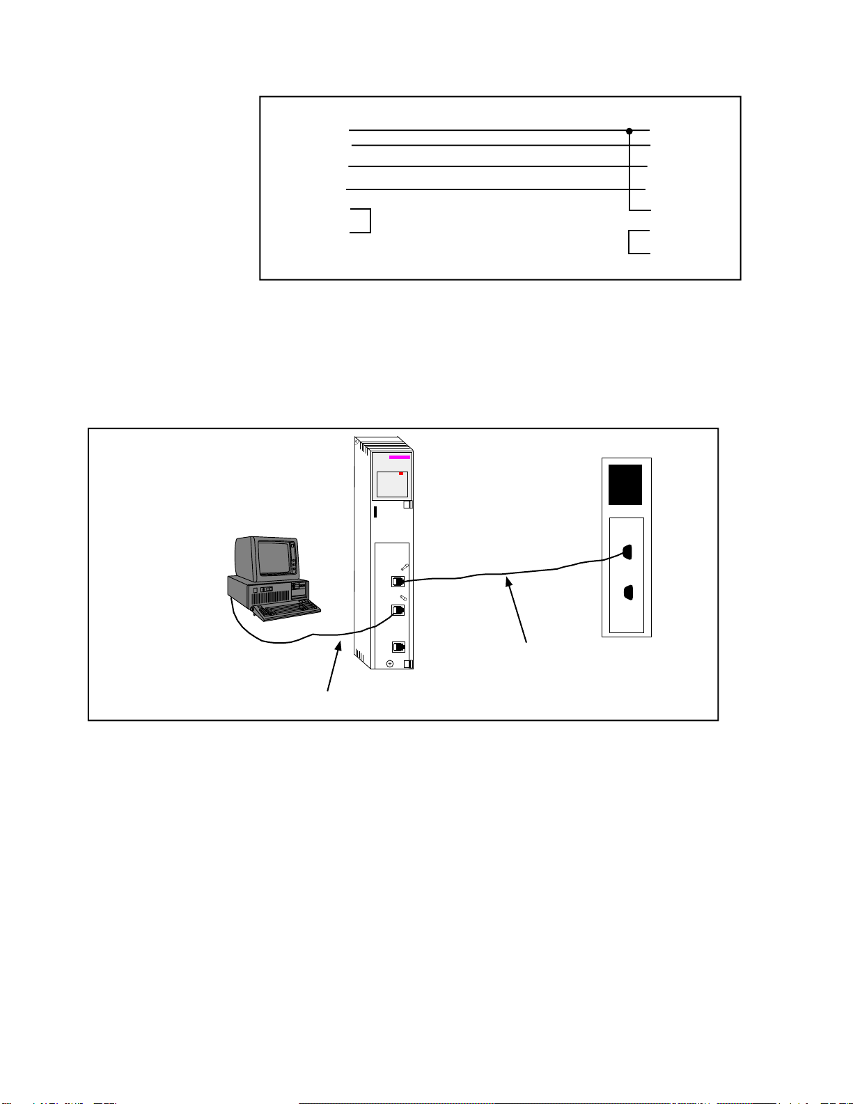
3964(R) to QUCM Port 2
After the software has been installed into the QUCM, Port 2 becomes the 3964(R)
port. The connection for the QUCM to the Euchner read/write head CIT3SX is an RJ-
45 connector on the QUCM side, and terminal screws at the Euchner device(Refer to
Figure 2-4).
Figure 2-4 QUCM-L RS-232 to Euchner read/write head CIT3SX
RJ45 Terminal Screws
32
44
53
6
7


QUCM 3964(R) Application Manual 3Modbus to 3964(R) Bridge 13
3
Modbus to 3964(R) Bridge
After the software has been loaded, and the RN1 light is lit, the QUCM is ready to be
used as a bridge between Modbus RTU and 3964(R). The master should use opcode
x03 for a read, and opcode x06 or x16 for writes. Any other opcode will not be trans-
lated. The master will transmit a normal modbus query, and the QUCM will translate
the query, providing the configured slave ID is used.
Configure QUCM
The QUCM is configured by a hyperterminal session. The PC is connected to the
QUCM’s Port 2 with an MM1 cable. Configure the hyperterminal session for 9600
baud, no parity, 8 data bits, 1 stop bit, no handshaking. The QUCM will set itself to
these settings, and transmit the configuration page when the Application 2 Run/Halt
switch is placed in the Memory Protect postion.
When the Application 2 switch has been set to Memory Protect, it will transmit the
configuration page to the hyperterminal. If at any time the information is not dis-
played, or is displayed incorrectly, pressing the Enter key will cause the QUCM to re-
transmit the same page. From this main page, the user can configure the Modbus port
and the 3964(R) port. The user can also select an option that will display all current
settings. To select an option, simply press the correspoding number for the option de-
sired. There is no need to press the Enter key.
Modbus Configuration
The Modbus configuration page allows the user to select the baud rate, parity, data
bits, stop bits, and slave ID that will be used to communicate with the Modbus master.
The defaults are 9600, Even, 8, 1, and 1, respectively. Be sure that these settings
match the settings for the master. Again, simply press the corresponding number for
the desired option.
When an option is selected, the QUCM will display the current setting, as well as all
available options for that particular setting. To accept the current setting, press the
Enter key. To change the setting, press the number of the desired option. The QUCM
will save that setting, and return to the previous configuration page. To exit the
Modbus configuration page, press the X key. This will return the user to the main
configuration page.

14 Modbus to 3964(R) Bridge 3QUCM 3964(R) Application Manual
3964(R) Configuration
The 3964(R) configuration page allows the user to change the settings for the 3964(R)
port. Possible settings are baud rate, parity, data bits, stop bits, and message timeout.
The first four are set in the same manner as for the Modbus port. Their default set-
tings are 9600, Even, 8, and 1, respectively.
The message timeout feature allows the user to select how long the QUCM will wait
for a reply to a query. The default timeout is 400ms. The timeout is fully programma-
ble by typing the desired time in milliseconds. Valid times are 0 to 30000ms.

QUCM 3964(R) Application Manual 4Examples 15
4
Examples
Example 1
Figure 4-1 displays an example Modbus to 3964(R) bridge using a Modicon
Bridge/Multiplexer to bridge between Modbus Plus and Modbus RTU. A Quantum
PLC polls the 3964(R) device across Modbus Plus, and the QUCM converts the mes-
sage to 3964(R).
The Quantum sends a query using the MSTR block out the Modbus Plus port with a
route of 35, 2, 1. Port 2 of the Bridge/MUX has been configured as a network port to
which multiple devices may be connected. The message is therefore received by the
Bridge/MUX(drop 35), translated to Modbus RTU, and routed out port 2 to slave de-
vice 1.
The QUCM will receive the Modbus RTU message at port 1 for device 1, translate the
message to 3964(R), and route it out port 2 to the 3964(R) device. When the 3964(R)
device responds to the query, the QUCM will receive the response at port 2, convert
the message to Modbus RTU, and route back out port 1. The Bridge/MUX will re-
ceive the reply, and route the appropriate Modbus Plus message back to the PLC.

16 Examples 4QUCM 3964(R) Application Manual
Figure 4-1 Modbus Plus Example
QUCM-L
140
QUCM
Niobrara
Active
Ready
Run
Col
Lnk
TXE
RXE
1
2
3
4
5
RN1
TX1
RX1
6
7
8
9
10
RN2
TX2
RX2
Fault Quantum
Bridge/MUX
MM2 Cable
MB+ = 1
MB+ = 35
3964(R)
MM1 Cable
Port 2

QUCM 3964(R) Application Manual 4Examples 17
Example 2
Figure 4-2 displays an example of how the QUCM could be used to put data from a
3964(R) device onto Modbus TCP.
This example allows the SMS computer to see the data in the 3964(R) device con-
nected to port 2 of the QUCM. The EPE5’s Port 1 must be set to Modbus Gate proto-
col, and an MM7 cable should be used between the EPE5 and the QUCM. The
QUCM’s port 1 must be set to RS-422 communications.
Table 4-1 shows the entry that must be in the Modbus Server table for the PC to be
able to communicate with the 3964(R) device. SMS will connect to the EPE5-TCP
using index 1. Index 1 points to the entry in the server table, and routes the message
out Port 1 to the QUCM, which sends the message to the 3964(R) device.
Figure 4-2 Modbus TCP Example
Table 4-1 Server Index Table For EPE5-TCP
1
2
3
4
EPE5
PLUS
E-net Act
E-net Err
Active
Busy
Error
EPE5-TCP-D
Personal Computer
running SMS-3000
Modbus Drop = 101
IP Address
206.223.51.33 IP Address
206.223.51.145
QUCM-L
140
QUCM
Niobrara
Active
Ready
Run
Col
Lnk
TXE
RXE
1
2
3
4
5
RN1
TX1
RX1
6
7
8
9
10
RN2
TX2
RX2
Fault
3964(R)
MM7 Cable
Drop TYPE Route
1 OTHER 101,1


QUCM 3964(R) Application Manual 5Troubleshooting 19
5
Troubleshooting
Module Lights
The QUCM-SE has several lights that indicate the status of the module. Table 5-1
shows the meanings of these lights.
Table 5-1 Module Lights
Light Meaning
Fault The module has a catastrophic fault.. Call the factory.
Active This light will be on if the module is in a traffic-copped slot in a Quantum PLC
system and the PLC is in RUN.
Ready This light should always be on (as long as it isn’t in firmware load).
Run This light will be on if the module is in a traffic-copped slot in a Quantum PLC
system and the PLC is in RUN.
Col Comes on when an Ethernet collision occurs.
Lnk Is on when LINK is established on the 10BaseT port.
TXE Comes on when the module is transmitting on the Ethernet port.
RXE Comes on when the module is receiving on the Ethernet port.
RN1 This light should be on to indicate app1 is running.
TX1 Comes on when the module is transmitting on serial port 1.
RX2 Comes on when the module is receiving on serial port 1.
RN2 This light should not come on since there is no app2 loaded.
TX1 Comes on when the module is transmitting on serial port 1.
RX2 Comes on when the module is receiving on serial port 1.

20 Troubleshooting 5QUCM 3964(R) Application Manual
User Lights
The QUCM-SE has 10 application driven lights numbered 1-10. The meaning of
these lights while the APP1 program is running is shown in Table 5-2.
Table 5-2 User Light Definitions
Light Meaning
1 Lights when a Modbus message with opcode 3 is translated
2 Lights when a Modbus message with opcodes 6 or 16(dec) is translated
3 Not used
4 Not used
5 Not used
6 Not used
7 Not used
8 Lights when application is in CONFIG mode
9 Lights when application is in CONFIG mode
10 Lights when application is in CONFIG mode
This manual suits for next models
1
Table of contents
Popular Control Unit manuals by other brands

Emerson
Emerson XJ200 Installation and operating instructions

Siemens
Siemens CLM Series Instructions & installation

ALLEN & HEATH
ALLEN & HEATH Qu-24 reference guide

NuWave
NuWave SSRMAN-1BFS Series user manual

XIA
XIA microDXP Technical reference manual

KSB
KSB LevelControl Basic 2 Installation & operating manual


Telit Wireless Solutions
Telit Wireless Solutions GL865-QUAD V4 Software user's guide

Omnivision
Omnivision OVMed-A1 DVP user manual

RDZ
RDZ WI-SA Technical installation manual

Comeval
Comeval UNIFLOW 3P Installation, operating and maintenance manual

M-system
M-system R6N-RS2 instruction manual

Goetze
Goetze 2140 Assembly and maintenance instructions