GE CR194 User manual

CR
194
Vacuum
Limitamp
Control
One
-
High
Controllers
with
Stationary
M
Vacuum
Contactors
Caution
:
Product
is
not
i
ount
Wended
for
nuclea
ruse
.
Utilization
Voltage
-
2.4
through
7.2
kVac
26
-
wide
and
34
-
wide
,
One
-
High
,
400
Amp
(
For
48
-
wide
,
800
Amp
see
GEH
-
5396
)
,
/
$
-
t
*
H
v
4
%
k
*
>
'
I
*
*
$
3
mttin
pifclkiraiiiii
f
iiaiOTMflli
1
MU
4
*
-
*
4
«
$
%
*
*
*
tI
pfiKHi
liiliU
C
‘
«
wasii
Courtesy of NationalSwitchgear.com

CR
194
Vacuum
Limitamp
400
Ampere
Control
Table
of
Contents
Introduction
3
4
Description
Equipment
Identification
-
CR
Number
Designation
.
.
,
.
4
General
.
.
.
.
.
;
Ratings
Basic
Impulse
Level
(
BIL
)
Dielectric
Test
Voltage
High
Voltage
Vacuum
Contactors
Blown
Fuse
Indicator
Manual
Disconnect
(
Isolating
Mechanism
)
Mechanical
Interlocking
Auxiliary
Enclosures
Dimensions
Power
Fuses
Power
Fuse
Conversion
Instructions
Starting
Autotransformers
8
c
Reactors
Installation
General
Receiving
Handling
Placement
of
Enclosure
Disassembly
Disassembly
Sequence
of
Operation
Grounding
Incoming
Power
Connections
Motor
Connections
Extra
-
width
Enclosure
Power
Cable
Termination
Control
Connections
Reassembly
Replacing
Contactor
In
Enclosure
Mechanical
Operation
Check
Operation
General
Test
-
power
Circuit
Preparation
of
Controller
for
Operation
Normal
Operation
Door
Opening
Procedure
Inspection
,
Maintenance
,
8
c
Servicing
Vacuum
Contactor
Isolating
Mechanism
and
Mechanical
Interlock
Checking
Procedures
-
*
Mechanical
Interlock
&
Manual
Isolator
Vacuum
Interrupter
Integrity
Test
Test
Procedure
Preventive
Maintenance
Guide
4
5
5
5
5
8
8
..
.
8
10
10
11
11
11
13
13
13
13
13
13
13
14
14
19
20
20
23
24
24
24
27
27
27
27
27
27
29
29
29
31
31
31
32
2
Courtesy of NationalSwitchgear.com

CR
194
Vacuum
Limitamp
400
Ampere
Control
The
essential
control
functions
for
all
types
of
a
-
c
motors
consist
of
starting
,
stopping
,
and
overload
protection
.
Vacuum
Limitamp
controllers
also
include
short
-
circuit
protection
,
but
other
functions
are
provided
in
each
controller
as
they
are
applicable
to
the
type
of
motor
being
controlled
(
such
as
synchronous
and
wound
-
rotor
motors
)
.
Also
,
special
functions
are
provided
in
great
variety
as
may
be
required
for
particular
applications
.
These
instructions
were
prepared
as
a
guide
to
handling
,
installation
,
operation
and
maintenance
of
all
one
-
high
,
400
Amp
types
of
Vacuum
Limitamp
controllers
.
This
includes
the
26
-
inch
wide
one
-
high
and
the
34
-
inch
wide
one
-
high
controller
.
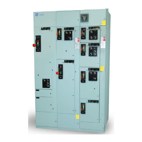
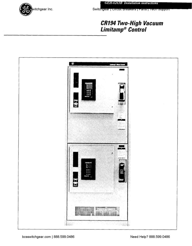
Figure
1
shows
a
26
-
inch
wide
controller
and
Figure
2
shows
a
34
-
inch
wide
synchro
-
nous
controller
.
The
intent
of
these
instructions
is
to
give
the
Purchaser
the
necessary
general
information
to
identify
his
control
-
ler
as
to
type
and
function
,
to
describe
suggested
methods
of
installation
,
and
to
demonstrate
some
techniques
of
operation
and
maintenance
.
The
Pur
-
chaser
should
interpret
these
instructions
for
applicability
to
his
particular
controller
by
referring
to
the
nameplate
data
on
the
controller
and
to
the
electri
-
cal
diagrams
supplied
with
the
controller
.
If
the
controller
is
for
a
synchronous
motor
,
these
instructions
should
be
used
with
GEH
-
5201
.
For
applica
-
tions
questions
refer
to
GET
-
6840
.
For
details
on
high
-
voltage
contactor
refer
to
GEH
-
5306
.
Warning
:
Before
any
adjustments
,
servicing
,
parts
replacement
or
any
other
act
is
performed
requiring
physical
contact
with
the
electrical
working
components
or
wiring
of
this
equipment
,
power
must
be
removed
from
all
sources
and
all
attached
rotating
equipment
must
have
come
to
a
complete
stop
.
User
personnel
must
be
completely
familiar
with
the
following
operating
and
maintenance
instructions
before
attempting
to
service
this
equipment
.
Warning
:
The
vacuum
interrupter
integrity
test
should
be
performed
before
the
high
-
voltage
,
vacuum
contactor
is
energized
for
the
first
time
and
each
time
the
contactor
is
returned
to
service
after
maintenance
,
adjustment
,
or
repair
.
Failure
to
perform
this
test
may
result
in
serious
injury
or
death
.
Introduction
Vacuum
Limitamp
controllers
are
designed
to
meet
NEMA
ICS
2
-
324
“
AC
General
Purpose
High
-
voltage
Class
E
Controllers
”
and
UL
347
requirements
,
and
may
be
described
as
metal
-
enclosed
high
-
interrupting
capacity
,
vacuum
-
contactor
-
type
starter
equipments
with
manual
isolation
.
Individual
starters
and
controllers
are
de
-
signed
for
specific
applications
;
the
components
and
functions
being
dictated
by
the
Purchaser
specifications
and
needs
.
Controllers
may
be
fused
or
unfused
.
Figure
1
.
26
-
inch
wide
one
-
high
controller
.
Figure
2
.
34
-
inch
wide
synchronous
controller
.
3
Courtesy of NationalSwitchgear.com

CR
194
Vacuum
Limitamp
400
Ampere
Control
Description
Equipment
Identification
-
CR
Number
Designation
Basic
type
designation
for
all
Vacuum
Limitamp
Control
equipment
is
CR
194
with
significant
alpha
-
numeric
suffixes
used
to
define
rating
,
function
,
contactor
type
and
enclosure
type
.
CR
194
NEMA
TYPE
1
=
NEMA
E
1
(
Unfused
)
2
=
NEMA
E
2
(
Fused
)
Starling
and
Spaed
Functions
—
Enclosure
A
—
26
"
1
-
HI
B
—
34
"
1
-
Hl
A
—
Single
-
speed
,
full
voltage
sB
—
Single
-
speed
,
reduced
voltage
reactor
type
b
—
Single
-
speed
,
reduced
voltage
autotransformer
type
D
—
Single
-
speed
,
part
winding
start
E
—
Single
-
speed
,
reduced
voltage
primary
resistor
G
—
2
speed
,
1
winding
full
voltage
H
—
2
speed
,
1
winding
reactor
reduced
voltage
J
—
2
speed
,
1
winding
autotransformer
reduced
voltage
N
—
2
speed
,
2
winding
full
voltage
P
—
2
speed
,
2
winding
reactor
reduced
voltage
Q
—
2
speed
,
2
winding
autotransformer
reduced
voltage
System
Voltage
7
—
2400
Volts
8
—
4200
Volts
2
—
7200
Volts
0
—
Other
Controlled
Apparatus
0
—
Synchronous
Motor
(
brushless
type
)
1
—
Induction
Motor
2
—
Synchronous
Motor
(
ring
type
)
3
—
Wound
Rotor
Motor
4
—
Transformer
Feeder
5
—
Capacitor
Feeder
6
—
Other
Rotation
and
Braking
1
—
Non
reversing
/
non
braking
2
—
Reversing
/
non
braking
4
—
Non
reversing
/
dynamic
braking
5
—
Reversing
/
dynamic
braking
7
—
Reversing
/
plugging
In
general
,
the
unit
enclosures
are
divided
into
high
-
voltage
and
low
-
voltage
compartments
,
each
with
its
own
separate
door
and
with
interior
barriers
between
the
two
.
See
Figures
3
,
4
,
and
5
.
To
open
the
high
-
voltage
compartment
door
,
the
power
must
be
disconnected
by
a
sequence
of
manual
operations
which
requires
de
-
energizing
the
high
-
voltage
contactor
,
operating
the
isolating
switch
handle
,
and
unlatching
the
door
*
Low
-
voltage
doors
may
be
entered
without
disconnecting
the
power
;
however
,
this
should
be
done
with
extreme
care
and
caution
The
upper
compartment
of
one
-
high
controllers
may
contain
a
low
-
voltage
panel
,
hinged
on
the
left
side
,
which
acts
as
a
barrier
to
the
high
-
voltage
control
power
transformer
mounted
on
the
upper
rear
cover
.
General
The
basic
Vacuum
Limitamp
controller
is
a
front
-
connected
assembly
of
components
and
conductors
for
motor
starting
,
arranged
for
convenient
access
,
in
an
enclosure
which
allows
space
and
facilities
for
cable
termination
,
plus
safety
interlocking
of
doors
and
isolator
to
prevent
inadvertent
entrance
to
high
-
voltage
parts
.
No
back
access
is
required
.
This
equipment
may
be
rated
up
to
7.2
kV
depending
on
the
contactor
and
fuse
ratings
.
Installation
,
operation
,
and
service
should
be
performed
only
by
experienced
personnel
trained
in
this
class
of
equipment
.
4
Courtesy of NationalSwitchgear.com

CR
194
Vacuum
Limitamp
400
Ampere
Control
Interrupting
Ratings
At
Utilization
Voltage
Shown
Three
-
phase
Symmetrical
System
MVA
Maximum
Continuous
Amperes
(
RMS
)
Maximum
Volts
Class
E
1
Unfused
Class
E
2
Fused
2500
400
29
200
400
5000
50
400
400
7200
50
600
Basic
Impulse
Level
(
BIL
)
The
standard
BIT
rating
of
Vacuum
Limitamp
control
-
lers
is
60
kV
crest
(
design
rating
)
.
This
rating
excludes
dry
-
type
control
transformers
and
starting
reactors
or
au
totran
sformers
.
Dielectric
Test
Voltage
2
1
/
4
x
nameplate
voltage
plus
2000
volts
.
High
-
voltage
Vacuum
Contactors
The
vacuum
contactors
used
in
Vacuum
Limitamp
controllers
are
available
in
two
different
ratings
:
400
and
800
amperes
.
This
publication
covers
only
the
400
ampere
rating
.
The
contactors
are
similar
in
operation
but
very
different
in
size
and
rating
.
For
this
reason
they
are
not
directly
interchangeable
mechanically
.
See
Figure
7
.
The
contactors
are
easily
removable
from
the
controller
assembly
by
removing
a
few
bolts
that
hold
the
contactor
in
position
and
by
disconnecting
the
line
and
load
power
connections
.
The
auxiliary
contacts
and
the
coil
termi
-
nals
are
connected
by
means
of
a
removable
connector
that
is
retained
by
two
wing
nuts
.
By
removing
these
wing
nuts
,
the
wiring
harness
is
easily
disconnected
from
the
contactor
.
Refer
to
the
information
beginning
on
Page
13
of
this
publication
that
details
the
correct
method
for
contactor
removal
.
Figure
3
.
26
-
inch
wide
400
-
ampere
FVNR
starter
,
Ratings
Refer
to
the
panel
data
nameplate
(
see
Figure
6
)
on
front
of
the
enclosure
for
detailed
ratings
applicable
to
a
particular
controller
.
Equipment
basic
ratings
equal
or
exceed
NEMA
ICS
2
-
324
for
Class
E
2
Controllers
,
and
are
summarized
below
.
Approximate
Maximum
Horsepower
,
Current
8
c
Voltage
Ratings
2200
-
2400
Volts
4000
-
4800
Volts
7200
Volts
Synchronous
Motors
Synchronous
Motors
Synchronous
Motors
Continuous
Current
(
RMS
)
(
Amperes
)
Induction
Motors
Induction
Motors
Induction
Motors
0.8
PF
0.8
PF
1.0
PF
1.0
PF
0.8
PF
•
1.0
PF
400
Max
.
3450
1600
1600
3725
4800
2000
3450
4800
6000
Note
:
Above
ratings
apply
to
controllers
in
NEMA
1
,
vented
enclosures
,
at
4
CP
C
ambient
.
5
Courtesy of NationalSwitchgear.com

CR
194
Vacuum
Limitamp
400
Ampere
Control
mmm
.
.
fit
.
.
P
^
M
4
*
*
vt
LM
/
/
im
ki
.
i
<
k
»
#
»
^
.
«
>
i
«
,
-
-
K
«
T
*
<
»
crl
Vlt
%
.
t
*
l
.
I
1
M
•
“
W
<
-
*
<
I
’
K
f
»
:
»
•
r
1
,
1
*
«
_
_
_
_
_
V
,
'
.
v
:
:
Jvi
'
-
'
•
:
.
*
:
*
,
iV
v
.
u
.
-
i
r
.
i
w
*
PANEL
*
DATA
/
NAMEPLATE
/
m
<
H
.
''
J
'
HWIWUim
i
'
i
;
•
•
;
i
kJ
>
6
%
I
r
aae
-
1
if
!
1
'
"
•
ii
*
“
RSKSftj
-
c
rr
-
Jj
5
>
•
•
*
;
I
*
•
-
'
1
V
.
m
7
ft
$
:
i
n
.
•
-
.
“
<
l
’
-
7
MM
!
CfllVMIliM
<
msm
.
i
i
*
;
•
*
'
v
$
#
1
>
K
;
-
r
.
-
.
i
V
£
:
-
-
*
:
•
•
i
s
S
-
S
:
fi
.
•
‘
_
*
>
‘
.
v
.
r
Figure
6
.
Panel
data
nameplate
.
Figure
4
.
34
-
Inch
wide
400
-
ampere
FVNR
synchronous
starter
low
-
voltage
control
section
.
1
C
i
a
'
•
>
-
5
*
i
t
pa
f
1
i
feft
>
:
f
:
•
VX
.
\
i
1
s
•
4
'
:
«
FC
..
:
•
t
-
.
V
:
/
.
s
•
K
3
S
Figure
7
.
The
800
and
400
ampere
vacuum
contactors
.
Figure
5
.
34
-
inch
wide
400
-
ampere
FVNR
synchronous
starter
high
-
voltage
section
showing
the
400
-
ampere
contactor
.
c
6
Courtesy of NationalSwitchgear.com

CR
194
Vacuum
Limitamp
400
Ampere
Control
tent
-
AS
~
;
Figure
10
.
Anti
single
-
phase
contact
block
-
wiring
removed
for
clarity
.
Figure
8
.
High
-
voltage
compartment
showing
fuse
assembly
.
v
‘
.
*
-
VS
..
.
1
•
>
'
r
*
u
,
v
.
’
T
:
.
Figure
11
.
View
of
disconnect
switch
in
the
CLOSED
position
.
Barriers
are
removed
for
clarity
.
Figure
9
.
View
of
various
low
-
voltage
components
on
swing
panel
.
7
Courtesy of NationalSwitchgear.com

CR
194
Vacuum
Limitamp
400
Ampere
Control
Vacuum
Limitamp
Control
is
supplied
standard
with
bolt
-
in
type
fuses
.
The
fuse
holders
will
accommodate
2400
-
volt
through
7200
-
volt
fuses
.
The
length
of
these
types
of
fuses
vary
and
the
lower
fuse
mount
can
be
adjusted
to
the
proper
length
by
unbolting
the
mount
from
the
back
rail
and
remounting
it
in
the
proper
location
.
For
7200
-
volt
applications
,
the
fuses
require
a
slightly
different
lower
mounting
strap
and
the
top
fuse
mounting
strap
must
be
changed
.
This
requires
that
the
disconnect
switch
be
disassembled
.
See
Figure
8
.
Manual
Disconnect
(
Isolating
Mechanism
)
Vacuum
Limitamp
controllers
,
following
the
NEMA
definition
,
provide
a
means
for
manually
isolating
the
power
circuit
by
operation
of
a
disconnecting
device
.
The
disconnecting
mechanism
consists
of
a
quick
-
make
quick
-
break
,
non
-
load
break
disconnect
switch
(
see
Figures
11
through
13
)
which
is
controlled
by
the
operating
handle
(
see
Figure
6
)
.
A
fixed
barrier
(
Figure
13
)
,
with
a
viewing
window
,
is
supplied
to
provide
isolation
from
the
energized
bus
parts
.
There
are
no
The
vacuum
contactors
supplied
with
Vacuum
Limitamp
moving
shutters
that
require
maintenance
.
The
quick
-
Control
are
magnetically
operated
by
a
dc
coil
fed
by
an
make
,
quick
-
break
,
operating
mechanism
is
shown
in
integral
rectifier
and
timed
holding
circuit
.
A
base
Figure
15
.
mounted
contactor
timing
module
(
CTM
)
applies
full
voltage
to
the
contactor
coil
for
a
time
sufficient
to
fully
close
the
contactor
.
A
series
capacitor
is
then
switched
in
to
hold
the
contactor
closed
without
overheating
the
coil
.
Load
current
must
not
be
interrupted
by
the
disconnect
switch
.
A
mechanical
interlock
is
provided
to
ensure
that
the
contactor
is
in
the
open
position
before
the
operating
handle
can
be
actuated
.
Also
,
the
contactor
cannot
be
operated
while
the
operating
handle
is
being
moved
from
one
position
to
another
.
The
mechanical
isolator
will
accept
up
to
four
padlocks
to
prevent
operation
.
See
Figure
16
.
Blown
Fuse
Indicator
Blown
fuse
indication
is
activated
by
a
trip
bar
located
at
the
rear
of
the
top
fuse
holder
.
The
blown
fuse
indica
-
tor
requires
bolt
-
in
type
fuses
.
When
one
or
more
of
the
fuses
blow
,
a
small
indicator
moves
upward
from
the
top
center
of
the
fuse
to
indicate
which
fuse
has
blown
.
The
right
end
of
the
trip
bar
has
a
cam
that
operates
an
anti
-
single
phase
contact
which
is
wired
to
trip
the
controller
off
-
line
to
prevent
single
phasing
of
the
connected
load
.
See
Figure
10
.
Mechanical
Interlocking
Vacuum
Limitamp
equipment
is
designed
so
the
high
-
voltage
contactor
performs
all
normal
load
current
interrupting
.
The
current
-
limiting
fuses
generally
interrupt
the
fault
currents
.
Note
:
The
quick
-
make
quick
-
break
manual
isolator
will
not
interrupt
any
load
or
fault
current
.
'
A
mechanical
interference
system
is
included
with
all
Vacuum
Limitamp
controllers
(
mechanical
interlock
)
,
which
prevents
opening
of
the
manually
operated
isolating
contacts
unless
the
high
-
voltage
contactor
itself
is
demonstrated
by
magnet
position
to
be
already
open
.
This
is
to
ensure
that
the
contactor
has
opened
the
power
circuit
and
interrupted
the
current
before
the
disconnect
switch
may
be
operated
.
See
Figure
17
.
Warning
:
The
manual
isolator
should
never
be
forcibly
operated
.
Its
mechanical
interference
interlock
should
be
defeated
only
by
knowledgeable
and
qualified
electrical
mainte
-
nance
personnel
who
have
de
-
energized
all
poioer
feeding
the
controller
.
gpB
.
'
fcVlrB
SH
‘
4
'
:
1
mu
:
•
?
4
«
I
*
?
>
fi
\
'
4
'
'
"
1
m
m
-
W
•
*
*
4
.
.
Mi
H
)
-
v
.
-
P
.
i
•
>
V
:
i
f
&
iiW
!
[
,
,
„
>
1
g
§
*
M
-
•
•
•
T
~
&
.
<
*
*
*
*
i
/
*
sis
*
:
?
iif
:
:
>
*
:
-
r
.
Hi
J
!
!
;
Ji
:
-
-
:
^
li
'
’
n
-
w
*
’
)
Sv
.
s
>
•
'
l
,
m
P
i
f
.
if
Figure
12
.
View
of
the
disconnect
switch
in
the
OPEN
position
.
Barriers
are
removed
for
clarity
.
8
Courtesy of NationalSwitchgear.com

CR
194
Vacuum
Umitamp
400
Ampere
Control
*
*
•
-
!
.
i
f
•
>
!
•
v
V
:
5
‘
:
;
•
«
i
i
:
,
N
.
teil
'
.
c
fc
•
;
*
y
*
*
*
*
*
;
.
'
•
%
t
l
|
Figure
13
.
.
Disconnect
switch
shown
with
barrier
In
place
.
Switch
shown
In
CLOSED
position
.
Figure
15
.
View
of
quick
-
make
quick
-
break
operator
.
sfVV
T
:
•
"
i
•
‘
‘
42
:
-
.
*
WiV
;
'
•
-
'
-
>
V
t
!
£
;
i
*
.
<
resi
POWER
"
i
.
’
.
v
"
r
INTERLOCKS
.
!
.
«
>
5
'
f
V
.
.
1
4
:
r
!
”
'
v
V
*
KV
;
-
•
*
!
i
\
•
I
•
?
I
•
i
=
--
-
&
•
*
.
-
V
•
v
?
as
.
.
.
.
*
'
.
r
'
.
r
tm
l
m
•
c
.
i
4
f
.
'
V
$
•
i
r
-
>
3
*
v
i
•
*
3
>
a
.
-
*
*
;
L
f
:
'
*
*
'
s
48
(
^
189
i
t
-
•
«
v
JLfi
'
•
iMc
t
=
'
’
1
,
'
V
:
,
l
>
.
va
.
-
'
-
V
'
'
-
’
•
if
.
'
?
'
‘
^
V
.
Wmmm
.
•
?
V
;
:
i
^
5
V
'
•
r
-
-
^
Wp
-
r
"
=
'
V
.
i
••
•
;
?
.
5
•
;
.
/
r
5
;
!
.
,
I
(
•
.
,
:
.
-
*
••
i
t
•
•
.
.
f
w
:
-
r
-
'
ll
•
:
5
:
•
{
.
.
.
.
*
V
.
"
.
•
:
•
fif
-
:
.
J
Figure
16
.
The
operating
handle
for
the
disconnect
may
be
padlocked
to
prevent
operation
.
Figure
14
.
View
of
handle
assembly
area
showing
test
power
interlocks
.
9
Courtesy of NationalSwitchgear.com

CR
194
Vacuum
Umitamp
400
Ampere
Control
Warning
:
There
is
no
emergency
condition
that
can
justify
forc
-
ible
operation
of
the
manual
isolator
with
the
main
contactor
closed
.
The
isolator
must
be
operated
only
with
the
contactor
open
.
All
high
-
voltage
doors
are
interlocked
by
mechanical
interference
mechanism
that
lock
high
-
voltage
doors
closed
until
the
disconnect
switch
is
in
the
OPEN
position
.
This
is
done
to
prevent
exposure
to
high
-
voltage
.
In
one
-
high
controllers
the
bottom
door
covers
the
high
-
voltage
compartment
.
Other
high
-
voltage
doors
may
be
full
height
to
cover
high
-
voltage
parts
located
in
auxiliary
sections
.
These
devices
may
include
reactors
,
auto
trans
-
formers
or
control
power
transformers
,
etc
.
Key
interlocking
is
frequently
used
in
lieu
of
mechanical
interference
mechanisms
to
lock
high
-
voltage
doors
closed
until
power
inside
has
been
removed
.
Non
-
loadbreak
switches
are
also
key
interlocked
to
prevent
operation
under
load
.
In
all
cases
of
key
interlocking
,
it
is
important
to
follow
the
operating
sequence
as
de
-
scribed
on
the
drawings
furnished
with
the
equipment
.
On
some
one
-
high
enclosure
designs
,
a
low
-
voltage
control
panel
mounted
by
hinges
to
the
left
side
of
the
enclosure
serves
as
a
barrier
to
isolate
the
high
-
voltage
control
power
transformer
and
fuses
.
An
interference
latch
,
shown
in
Figure
54
,
prevents
swinging
this
panel
out
until
the
high
-
voltage
door
is
opened
,
thus
ensuring
that
high
-
voltage
power
to
the
Control
Power
Trans
-
former
is
disconnected
.
V
-
i
'
'
.
-
V
'
-
'
-
VS
-
•
V
i
-
X
-
V
•
.
jr
.
-
••
•
*
'
M
•
*
-
v
-
•
•
•
i
'
•
•
'
S
.
.
i
:
-
r
•
i
>
a
;
-
-
:
•
•
•
:
-
i
»
-
.
:
\
"
f
-
!
1
-
s
;
'
*
•
'
>
•
'
•
:
‘
V
V
.
V
'
-
.
V
-
.
'
-
'
i
V
;
r
•
V
-
t
'
:
V
>
,
v
*
i
-
:
v
.
-
V
-
.
-
.
v
;
s
*
=
^
X
$
r
-
.
v
-
*
.
i
.
-
k
.
.
3
yV
.
Figure
17
.
Contactor
engagement
pawl
for
mechanical
interlock
.
Auxiliary
Enclosures
Many
sizes
of
enclosures
are
furnished
in
Vacuum
Limitamp
control
lineups
for
various
purposes
.
Some
are
tabulated
below
;
Wound
rotor
,
secondary
contactor
and
resistor
compartments
Bus
transitions
to
switchgear
Bus
transitions
to
transformers
Cable
entrance
compartments
Rectifier
exciter
compartments
Starting
reactor
or
autotransformer
compartments
Relay
and
metering
compartments
Instrument
transformer
compartments
Manual
switch
compartments
Refer
to
Figure
60
for
details
.
Dimensions
Vacuum
Limitamp
controllers
are
normally
30
-
inches
deep
and
90
-
inches
high
.
Width
varies
for
one
-
high
controllers
,
induction
motors
,
synchronous
motors
other
special
applications
,
or
cable
space
requirements
Refer
to
Figure
60
for
typical
outline
dimensions
.
Figure
18
.
Blown
fuse
Indicator
shown
in
the
NORMAL
position
.
>
10
Courtesy of NationalSwitchgear.com

CR
194
Vacuum
Umitamp
400
Ampere
Control
Power
Fuses
Bolted
EJ
-
2
type
current
-
limiting
power
fuses
are
sup
-
plied
as
standard
with
Vacuum
Iimitamp
controllers
.
These
standard
fuses
are
bolt
-
in
type
because
the
blown
fuse
-
indicator
and
the
trip
bar
that
operates
the
anti
-
single
phase
contact
block
require
precise
alignment
of
the
striker
pin
at
the
top
of
the
fuse
with
the
operators
.
Clip
-
in
fuses
are
available
as
an
option
in
400
ampere
to
cover
requirements
for
EJ
-
1
type
fuses
,
but
the
“
anti
-
single
phase
”
indication
/
trip
functions
are
not
available
with
clip
fuses
.
Coordination
information
for
EJ
-
2
type
fuses
is
available
in
GES
-
5000
,
and
for
EJ
-
1
type
fuses
,
GES
-
5002
.
Interrupting
ratings
are
shown
on
page
5
of
these
instructions
.
Figure
18
shows
the
top
of
the
bolted
power
fuse
assembly
with
the
blown
fuse
indicators
in
the
normal
position
.
Power
Fuse
Conversion
Instructions
Bolt
-
in
fuses
used
on
Vacuum
Limitamp
and
Air
-
break
Limitamp
may
be
field
converted
from
one
to
the
other
by
carefully
following
the
instructions
below
.
Starting
Autotransformers
Sc
Reactors
Reduced
voltage
controllers
include
a
reactor
or
au
-
totransformer
designed
for
starting
duty
in
accordance
with
NEMAICS
2
-
214
.
The
duty
cycle
generally
fur
-
nished
is
for
medium
-
duty
applications
which
consist
of
three
30
-
second
starts
spaced
30
-
seconds
apart
followed
by
a
one
-
hour
rest
.
To
prevent
overheating
and
possible
damage
when
applied
on
more
severe
duty
(
heavy
duty
)
applications
,
special
reactors
or
autotransformers
must
be
specified
.
Thermostats
are
mounted
on
the
reactor
and
transformer
cores
to
offer
protection
against
over
-
heating
.
These
thermostats
must
be
manually
reset
if
tripped
by
high
temperature
.
SINGLE
BARREL
DOUBLE
BARREL
CAT
.
NO
.
55
A
21294
£
P
“
A
”
CAT
.
NO
.
218
A
4293
P
“
A
CAT
.
NO
.
55
A
212942
P
"
A
”
CAT
.
NO
.
218
A
4293
P
“
A
-
l
CAUTION
I
.
ICAUTIONI
I
CAUTION
I
ICAUTIONI
jNf
t
t
^
ijii
AJ
BY
CAREFULLY
FOLLOWING
THESE
INSTRUC
-
TIONS
,
THE
ABOVE
FUSE
VERSIONS
MAY
BE
FIELD
CONVERTED
FROM
ONE
TO
THE
OTHER
.
BY
CAREFULLY
FOLLOWING
THESE
INSTRUC
-
TIONS
,
THE
ABOVE
FUSE
VERSIONS
MAY
BE
FIELD
CONVERTED
FROM
ONE
TO
THE
OTHER
.
1
.
LOOSEN
BOTTOM
BOLT
(
Y
)
WHILE
INSURING
FUSE
BARREL
DOES
NOT
ROTATE
(
SEE
CAUTION
)
.
2
.
ROTATE
BOTTOM
STRAP
(
X
)
180
DEGREES
.
3
.
RETIGHTEN
BOTTOM
.
BOLT
(
B
)
TO
23
-
31
FT
/
LBS
WHILE
EN
-
SURING
THAT
FUSE
BARREL
DOES
NOT
TURN
.
1
.
LOOSEN
AND
REMOVE
BOTH
BOTTOM
BOLTS
(
Y
)
WHILE
IN
-
SURING
FUSE
BARREL
DOES
NOT
ROTATE
(
SEE
CAUTION
)
.
2
.
ROTATE
BOTTOM
STRAP
(
X
)
180
DEGREES
.
3
.
REINSTALL
BOTTOM
BOLTS
(
Y
)
AND
SPECIAL
SPRING
WASHER
(
BELLEVILLE
)
,
RED
PAINTED
STRIPE
ON
WASHER
TO
FACE
TOWARD
BOLT
HEAD
.
CAUTION
:
0
O
NOT
LOOSEN
TOP
BOLT
OF
FUSE
.
THIS
WILL
DAMAGE
INTERNAL
ELEMENTS
OF
FUSE
.
4
.
TIGHTEN
BOTTOM
BOLTS
(
B
)
TO
23
-
31
FT
/
LBS
WHILE
INSUR
-
ING
THAT
FUSE
BARREL
DOES
NOT
TURN
.
CAUTION
:
DO
NOT
LOOSEN
TOP
BOLT
OF
FUSE
.
THIS
WILL
DAMAGE
INTERNAL
ELEMENTS
OF
FUSE
.
11
Courtesy of NationalSwitchgear.com

CR
194
Vacuum
Limitamp
400
Ampere
Control
Figure
21
.
Recommended
method
of
lifting
single
panel
.
Figure
19
.
Vacuum
Limitamp
controller
wrapped
In
plastic
film
wrap
ready
for
shipment
.
gSipP
HBHHB
m
Figure
22
.
Recommended
method
of
lifting
a
Vacuum
Limitamp
lineup
.
Note
that
the
lineup
is
suspended
from
an
equalizing
bar
.
Figure
20
.
Vacuum
Limitamp
controller
with
outside
packaging
material
removed
and
ready
for
handling
.
t
?
Courtesy of NationalSwitchgear.com

CR
194
Vacuum
Limitamp
400
Ampere
Control
Installation
Placement
of
Enclosure
Ic
is
essential
that
the
controller
be
securely
fastened
in
an
upright
position
on
a
level
surface
to
allow
proper
functioning
of
the
internal
devices
.
While
there
are
no
roll
-
out
components
,
access
will
be
improved
if
the
controller
is
located
at
floor
level
with
plenty
of
room
allowed
for
doors
to
swing
fully
open
as
shown
on
the
drawings
supplied
with
the
equipment
.
After
the
controller
has
been
placed
in
position
,
the
floor
mounting
bolts
may
be
installed
and
tightened
.
The
location
of
these
bolts
is
shown
on
the
outline
drawing
furnished
with
each
controller
.
These
bolts
are
'
/
2
-
inch
bolts
and
are
usually
located
in
each
corner
of
the
controller
base
.
General
This
section
contains
information
on
receiving
and
handling
,
disassembly
,
power
-
cable
termination
,
ground
-
ing
,
and
reassembly
to
make
the
equipment
ready
for
operation
.
Receiving
Vacuum
Limitamp
controllers
are
fabricated
as
rigid
,
floor
-
mounted
,
self
-
supporting
steel
sections
requiring
no
floor
sills
.
They
are
crated
and
shipped
in
an
upright
position
and
,
when
received
,
should
be
kept
upright
.
Some
components
may
be
shipped
separately
,
such
as
tdp
-
mounted
resistors
or
potential
transformers
.
These
components
are
identified
by
catalog
number
coinciding
with
that
of
the
section
on
which
they
are
to
be
mounted
.
Plastic
film
wrap
or
corrugated
cardboard
is
normally
used
for
domestic
crating
with
the
steel
enclosure
sections
bolted
to
a
wooden
skid
.
See
Figure
19
.
After
receiving
,
the
packing
may
be
removed
and
the
equip
-
ment
handled
on
the
wooden
skid
.
See
Figure
20
.
Disassembly
After
the
equipment
has
been
set
in
place
where
it
is
to
be
permanently
connected
,
some
internal
disassembly
is
required
to
make
the
necessary
external
power
-
cable
and
control
-
wire
connections
.
Disassembly
should
be
done
in
a
definite
sequence
by
following
Figure
23
through
Figure
34
,
and
as
described
below
:
Disassembly
Sequence
of
Operation
Warning
:
Remove
all
power
from
the
equipment
before
proceed
-
ing
with
disassembly
.
1
.
Move
the
manual
isolator
handle
to
the
OFF
position
.
Refer
to
the
nameplate
attached
to
the
high
-
voltage
door
near
the
handle
.
Figure
23
-
2
shows
the
method
of
first
depressing
the
pusher
with
one
hand
and
moving
the
handle
with
the
other
.
Refer
to
page
27
and
29
for
normal
and
emergency
door
opening
procedures
.
2
.
Open
both
the
top
(
low
-
voltage
)
and
bottom
(
high
-
voltage
)
doors
.
Handling
It
is
always
preferable
to
handle
Limitamp
controllers
by
the
lifting
means
provided
.
Figure
21
shows
the
recom
-
mended
method
of
lifting
a
single
section
,
while
Figure
22
shows
the
recommended
method
of
lifting
a
lineup
.
Note
that
the
lineup
in
figure
22
is
suspended
from
an
equalizing
bar
.
A
lineup
should
be
supported
at
as
many
points
as
possible
.
If
there
is
not
enough
headroom
to
lift
the
panel
by
its
lifting
beam
,
then
a
track
jack
can
be
used
.
The
controller
can
be
raised
by
placing
a
track
jack
under
the
shipping
skid
.
Rollers
can
then
be
placed
under
the
skid
for
rolling
the
equipment
to
its
final
location
.
The
panel
should
then
be
raised
by
its
lifting
beam
,
the
shipping
skid
removed
,
and
the
panel
set
into
place
.
The
use
of
fork
-
lift
trucks
is
not
recommended
,
since
the
forks
may
damage
the
enclosure
or
interior
parts
of
the
equipment
,
and
the
equipment
becomes
very
unstable
when
lifted
from
the
bottom
.
If
no
other
method
of
handling
is
available
,
the
forks
must
go
under
the
skid
bottom
to
avoid
damaging
the
equipment
,
and
the
assembly
lifted
only
slightly
to
allow
the
skid
to
be
slid
along
a
flat
,
level
surface
.
However
,
the
recommended
method
is
by
crane
as
pictured
.
Contactor
Removal
Normally
it
is
not
necessary
to
remove
the
contactor
from
its
mount
in
order
to
make
external
power
-
cable
and
control
-
wire
connections
.
If
the
contactor
is
not
to
be
removed
proceed
to
Step
4
.
Otherwise
,
follow
the
steps
outlined
below
to
remove
the
contactor
from
the
controller
.
3
.
Contactor
removal
.
a
.
Remove
.
the
wing
nuts
holding
the
contactor
umbilical
cord
and
connectors
in
place
and
save
the
hardware
.
This
hardware
will
be
reused
to
remount
the
connector
when
the
contactor
is
reinstalled
.
Unplug
the
connector
and
place
the
bracket
in
the
lower
front
channel
to
the
left
of
the
contactor
for
safe
keeping
.
See
Figure
24
.
13
Courtesy of NationalSwitchgear.com

CR
194
Vacuum
Limitamp
400
Ampere
Control
Grounding
All
controller
enclosures
must
be
grounded
.
A
stud
is
welded
to
the
lower
back
of
the
enclosure
in
the
incom
-
ing
-
line
compartment
area
for
connection
to
the
grounding
system
.
This
connection
must
be
made
before
making
any
power
connection
.
If
ground
bus
is
ordered
,
the
ground
stud
is
connected
to
the
ground
bus
at
the
factory
and
the
system
ground
can
be
connected
to
the
ground
bus
instead
.
The
control
and
instrumentation
circuits
are
grounded
to
the
enclosure
at
the
terminal
board
.
This
is
normally
the
only
grounding
point
.
It
can
be
temporarily
re
-
moved
for
test
purposes
;
but
it
must
be
regrounded
before
the
control
is
returned
to
operation
.
b
.
Loosen
the
line
side
cable
bolts
at
the
bottom
of
the
fuse
assembly
and
save
the
hardware
.
Be
sure
the
cables
are
free
of
their
mounts
and
that
they
can
be
freely
removed
.
See
Figure
27
.
c
.
Remove
the
three
load
side
connection
bolts
in
the
bottom
of
the
contactor
.
These
bolts
are
accessed
through
the
openings
at
the
bottom
of
the
contactor
from
the
front
.
A
socket
wrench
with
an
extension
may
be
used
to
remove
these
bolts
.
Save
this
hardware
for
reuse
.
See
Figure
29
.
Note
:
Do
not
loosen
R
.
T
,
V
.
covered
bolts
.
cl
.
There
are
two
retaining
nuts
at
both
sides
on
the
lower
front
of
the
contactor
.
These
nuts
must
be
removed
.
See
arrows
in
Figure
29
.
o
.
Slide
the
contactor
out
of
the
mounting
base
and
lift
it
and
the
line
side
cables
out
of
the
enclosure
.
f
.
Replace
the
three
bolts
removed
from
the
load
side
connections
in
their
holes
and
thread
them
in
a
few
turns
.
These
bolts
will
prevent
reinstalling
the
contactor
until
removed
again
.
This
serves
as
a
reminder
that
the
bolts
are
there
and
need
to
be
reinstalled
when
the
contactor
is
being
replaced
.
4
.
Prepare
to
remove
the
horizontal
compartment
barrier
by
removing
the
two
bolts
shown
in
Figure
SO
.
5
.
Remove
the
horizontal
barrier
,
Figure
30
.
(
If
a
hinged
low
-
voltage
panel
is
used
,
swing
it
to
the
left
and
out
of
the
enclosure
.
)
<
6
.
Remove
the
horizontal
bus
barrier
bolts
as
shown
in
Figure
31
,
and
then
lift
the
barrier
out
of
the
enclosure
.
The
horizontal
bus
is
then
exposed
as
shown
in
Figure
32
.
Incoming
Power
Connections
Incoming
power
connections
to
the
bus
may
be
made
in
any
one
of
the
enclosures
in
a
lineup
.
Space
for
one
500
-
MCM
cable
with
stress
cones
per
phase
is
available
in
the
standard
26
-
inch
wide
enclosure
.
A
34
-
inch
wide
enclosure
is
also
optionally
available
when
larger
cable
capacities
are
required
.
The
34
-
inch
enclosure
is
standard
with
synchronous
controllers
and
7200
volt
controllers
.
If
shielded
cable
is
used
,
refer
to
the
information
on
Page
23
of
this
manual
.
In
the
one
-
high
enclosure
with
horizontal
power
bus
,
incoming
power
connections
are
made
on
the
left
end
of
the
bus
bars
.
When
the
barriers
are
removed
from
the
enclosure
,
both
ends
of
the
power
bus
and
the
ground
bus
are
accessible
from
the
inside
of
the
enclosure
.
To
add
additional
units
to
a
line
-
up
of
enclosures
,
the
new
7
.
Detach
the
switch
barrier
with
the
viewing
window
by
enclosure
can
be
located
in
position
and
,
with
the
bus
removing
the
ten
bolts
,
Figure
33
.
Pull
the
barrier
out
of
the
enclosure
.
splices
furnished
with
the
equipment
,
the
bus
connec
-
tions
can
be
made
to
either
side
of
the
existing
equipment
.
Figures
32
and
35
show
the
accessibility
of
both
ends
of
the
bus
bars
with
the
barriers
removed
and
8
.
Remove
the
front
cover
of
the
lower
incoming
line
barrier
,
Figure
34
,
(
if
incoming
cables
are
to
be
routed
from
the
floor
)
or
remove
the
top
incoming
line
barrier
(
if
cables
are
to
be
routed
into
the
enclosure
from
the
top
)
.
After
the
preceding
steps
have
been
completed
,
all
power
termination
points
and
bus
connections
arc
accessible
.
See
Figure
35
.
the
low
-
voltage
panel
swung
out
.
The
splices
must
be
bolted
in
place
with
the
14
-
inch
hardware
supplied
with
the
splice
kit
.
Torque
splice
bolts
to
35
lb
.
-
ft
.
14
Courtesy of NationalSwitchgear.com

CR
194
Vacuum
Limitamp
400
Ampere
Control
!
-
*
:
&
$
$
Tiiiw
'
•
J
f
*
>
Hid
£
p
?
-
T
-
:
:
f
:
f
V
.
:
.
.
-
V
V
:
'
1
•
'
v
.
vi
'
"
?
V
.
>
:
-
•
^
v
•
;
‘
r
-
V
v
..
•
vv
,
V
i
•
i
,
*
o
.
.
^
;
.
1
:
>
r
;
i
'
h
>
f
T
*
“
i
.
•
iv
.
Wi
.
-
S
-
:
?
&
:
:
%
I
.
-
Figure
30
,
Remove
the
bolts
shown
and
slide
the
horizontal
barrier
out
of
the
enclosure
.
Figure
28
.
Unbolt
the
cables
from
the
bottom
of
the
fuse
assembly
.
i
:
f
-
.
REMOVE
NUTSfv
•
>
••
m
"
'
,
K
7
!
.
S
'
!
.
:
!
;
i
Figure
31
.
Remove
the
horizontal
main
bus
barrier
bolts
shown
and
remove
the
barrier
.
Figure
29
.
Remove
the
three
load
-
side
connecting
bolts
,
(
do
not
adjust
the
R
.
T
.
V
.
covered
bolts
)
Remove
the
two
retaining
nuts
.
!
17
Courtesy of NationalSwitchgear.com

CR
194
Vacuum
Limitamp
400
Ampere
Control
•
:
?
!
I
>
]
'
^
v
.
/
•
#
|
f
*
3
Lv
*
<
•
•
*
T
i
’
vv
-
.
v
$
9
%
i
.
.
.
v
-
v
-
1
m
.
w
®
«
Illfllllfsj
*
#
-
v
*
Vf
Figure
32
*
Exposed
main
bus
after
removal
of
main
bus
barrier
.
Figure
34
.
Lower
Incoming
line
barrier
.
,
?
f
/
Vi
-
;
i
•
V
•
f
-
•
v
:
’
-
\
*
•
.
-
V
.
!
#
i
t
;
:
I
'
^
i
f
,
.
1
:
<
1
•
i
"
•
l
(
o
7
'
.
;
I
•
*
.
m
.
I
-
4
-
$
*
Figure
35
.
Main
bus
compartment
with
all
barriers
removed
and
incoming
line
cables
terminated
.
Figure
33
.
Isolator
switch
barrier
showing
bolts
to
be
removed
.
18
Courtesy of NationalSwitchgear.com

CR
194
Vacuum
Limitamp
400
Ampere
Control
Motor
Connections
Motor
cables
may
enter
from
the
top
or
bottom
of
the
enclosure
.
In
the
one
-
high
enclosure
,
the
motor
termi
-
nals
arc
located
on
the
inside
lower
left
wall
as
shown
in
Figure
36
.
The
incoming
leads
should
be
trained
for
maximum
space
between
phases
and
ground
.
The
connections
may
be
made
before
or
after
energizing
the
main
bus
and
without
shutting
down
adjacent
equip
-
ment
.
Also
see
Figure
60
.
Warning
:
If
the
main
bus
in
energized
while
load
cables
are
be
-
ing
installed
,
all
barriers
must
be
in
place
and
the
disconnect
switch
must
be
in
the
off
position
and
the
blades
must
be
visu
-
ally
checked
to
ensure
that
they
are
completely
disconnected
from
the
vertical
bus
.
The
motor
terminals
can
accommodate
up
to
one
500
-
MCM
per
phase
with
stress
cones
in
the
standard
26
-
inch
wide
enclosure
.
If
larger
cable
entries
are
required
,
an
optional
84
-
inch
wide
cabinet
is
available
.
Figure
36
.
Load
terminals
located
on
the
left
wall
of
the
high
-
voltage
compartment
.
The
lower
incoming
line
barrier
and
Isolator
switch
barrier
have
been
removed
.
Phase
A
is
at
the
top
.
19
Courtesy of NationalSwitchgear.com

CR
194
Vacuum
Limitamp
400
Ampere
Control
Extra
-
width
Enclosure
A
.
special
34
-
inch
-
wide
enclosure
is
available
for
terminat
-
ing
shielded
cable
with
stress
cones
,
or
for
terminating
more
than
one
large
cable
per
phase
.
The
enclosure
design
permits
space
for
termination
of
two
500
-
MCM
cables
per
phase
with
stress
cones
*
for
motor
and
power
leads
.
Figures
35
and
38
show
the
space
available
in
this
extra
-
width
enclosure
.
Design
is
basically
the
same
as
the
26
-
inch
-
wide
one
-
high
,
and
all
data
and
information
in
these
instructions
applicable
to
the
26
-
inch
one
-
high
design
apply
to
the
34
-
inch
-
wide
enclosure
.
Power
Cable
Termination
In
any
installation
,
the
cable
should
be
prepared
for
termination
in
accordance
with
the
instructions
of
the
cable
manufacturer
.
However
,
the
following
general
recommendations
are
given
for
proper
cable
termina
-
tion
in
Vacuum
Limitamp
equipment
.
1
.
Pull
in
the
cables
in
accordance
with
the
panel
outline
diagram
and
position
them
for
maximum
clearance
between
phase
,
ground
and
other
cable
or
wire
runs
.
Refer
to
Figure
60
of
these
instructions
for
recommended
location
of
incoming
cables
in
a
standard
Limitamp
controller
.
Figure
38
.
Motor
cable
terminations
in
26
-
Inch
or
34
-
inch
wide
enclosures
.
Figure
39
.
Termination
of
cable
in
potheads
.
*
General
Electric
Termi
-
Kit
®
stress
cones
.
20
Courtesy of NationalSwitchgear.com
Other manuals for CR194
2
Table of contents
Other GE Control Unit manuals

GE
GE Dialog User manual

GE
GE Intellix BMT 330 User manual

GE
GE Becker 3.5M Series User manual

GE
GE NetworX Series User manual

GE
GE MM200 User manual

GE
GE Multilin MM300 User manual

GE
GE TLE Scalable 150 User manual

GE
GE EntelliGuard TU User manual
GE
GE Masoneilan 77-6 User manual

GE
GE MiCOM P40 Agile User manual

GE
GE B30 UR Series User manual

GE
GE Spectra Series User manual

GE
GE 12000 Parts list manual

GE
GE PACSystems RX3i IC695ETM001-JW User manual

GE
GE 3020511 User manual

GE
GE Mini COM Express 10 Quick user guide

GE
GE WH18X28174 Configuration guide

GE
GE VersaSafe VersaPoint IC220SDL840 User manual

GE
GE EX2100 User manual

GE
GE IC3645SR4W746N5 User manual