Bartec 07-61.1 Series Quick start guide

Operational Instruction (Translation) Miniature Control and Display Unit
Type 07-61.1-…./….
BARTEC GmbH Max-Eyth-Straße 16
97980 Bad Mergentheim
Germany
Tel.: +49 7931 597-0
Fax: +49 7931 597-119
www.bartec.de
Reservation Technical data subject to change without notice. Changes, errors and
misprints may not be used as a basis for any claim for damages.
EN 1/4
Explosion protection Technical data
Maximum Ex type of protection
Depends on the installed components; ob-
serve the specifications on the type label.
ATEX/IECEx
II 2G
Ex d e [ib] IIC T6, T5
or T4 Gb
II 2(1)G
Ex d e [ia Ga] IIC T6, T5
or T4 Gb
II 2G
Ex d e IIC T6 or T5 Gb
II 2D
Ex tb [ib] IIIC T80 °C or
T95 °C Db
II 2(1)D
Ex tb [ia Da] IIIC T80 °C
or T95 °C Db
II 2D
Ex tb IIIC T80 °C or
T95 °C Db
0044
Certification
ATEX
EPS 14 ATEX 1 696
IECEx
IECEx EPS 14.0042
INMETRO
Ex d e [ib] IIC T6…T4 Gb
Ex d e [ia Ga] IIC T6…T4 Gb
Ex d e IIC T6…T5 Gb
Ex tb [ib] IIIC T80 °C…T95 °C Db
Ex tb [ia Da] IIIC T80 °C…T95 °C Db
Ex tb IIIC T80 °C…T95 °C Db
Certification
NCC 14.02943
TC RU C-DE.ГБ06.В.00443
Ambient temperature ranges
Depending on the installations; observe the
specifications on the type label.
-20 °C up to max. +70 °C
(-4 °F up to max. +158 °F)
Approved for Zones
1, 2 and 21, 22
Components
Follow the components manufacturer’s
mounting instructions and safety instructions.
Other applicable documents
– Circuit diagram
– Mounting instructions/operating instruc-
tions for the installed components
– Delivery note
The retention of these documents is manda-
tory.
Electrical data
Rated insulation voltage: max. 690 V
Rated current/installation
elements:
max. 21 A
Power loss: max. 8 W
Nominal connection cross
section:
max. 2.5 mm²
(14 AWG),
see type label
for precise
details
Protection class
Max. IP 66 (EN 60529)
Mechanical strength
Impact energy: max. 7 Nm
Enclosure material
– Aluminium, surface bare/coated
– Stainless steel
– Brass, surface bare/nickel-plated
Cover closure
Cheese head screw,
ISO 4762-M4x14-A2-70 or
ISO 4762-M5x14-A2-70
Dimensions
See page 3.
01-6100-7D0002/B-02/15-STVT-283184
Note on instructions
When working in hazardous areas, the safety o
f
personnel and equipment depends on compli-
ance with the relevant safety regulations. The
people in charge of installation and mainte-
nance bear a special responsibility. It is essen-
tial that they have an exact knowledge of the
applicable rules and regulations.
The instructions provide a summary of the most
important safety measures and must be read by
everyone working with the product so that they
will be familiar with the correct handling of the
product.
The instructions have to be kept for future
reference and must be available throughout the
expected life of the product.
Description
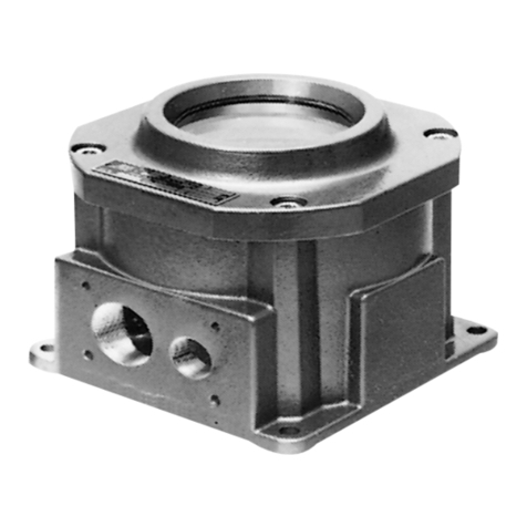
The miniature control and display unit, type 07-
61.1-…./…. and type 07-662.-…./…., serves as
a flameproof enclosure for switching, control,
regulating and display devices in an industrial
quality.
A
lternatively, certified intrinsically safe
or associated apparatus can be fitted too.
The miniature control and display units consist
of an enclosure with the “flameproof enclosure”
type of protection and optionally a bearing
assembly with shafts and/or a flange with
“flameproof”-certified washers.
For connection purposes, there is either a
j
unction box with “increased safety” type o
f
protection or Ex d certified cable and conducto
r
entries.
The miniature control and display unit can be
used in hazardous areas in Zones 1 and 2 in
accordance with the certified explosion hazard
sub-groups IIA, IIB and IIC and the temperature
class T4/T5/T6, as well as in Zones 21 and 22
in accordance with the certified max. surface
temperature (see type label).
If the miniature control and display units contain
intrinsically safe circuits or Ex i components, the
electrical limits that are decisive for “intrinsic
safety” must be adhered to.

Operational Instruction (Translation) Miniature Control and Display Unit
Type 07-61.1-…./….
BARTEC GmbH Max-Eyth-Straße 16
97980 Bad Mergentheim
Germany
Tel.: +49 7931 597-0
Fax: +49 7931 597-119
www.bartec.de
Reservation Technical data subject to change without notice. Changes, errors and
misprints may not be used as a basis for any claim for damages.
EN 2/4
01-6100-7D0002/B-02/15-STVT-283184
Safety Instructions
The miniature control and display unit may be
used only within the specified temperature
class and the temperature range indicated for it
(see type label). The miniature control and
display unit is not suitable for use in Zones
0/20.
The miniature control and display unit may be
operated only if it is clean and not damaged in
any way. Dust deposits > 5 mm (> 0.2 in) must
be removed.
Utilization in areas other than those specified
and the opening or modification of the product
by anyone other than the manufacturer are not
permitted and will exempt BARTEC from lia-
bility for defects and any further liability.
The generally applicable statutory rules and
other binding directives relating to workplace
safety, accident prevention and environmental
protection must be observed.
When using electrical systems, the relevant
installation and operating conditions must be
observed. The specifications on the type label
must be adhered to.
Observe the applicable laws and directives
when commissioning or restarting operation.
Always follow the safety instructions on the
operating equipment.
Marking
Particularly important points in these instruc-
tions are marked with a symbol:
DANGER indicates a hazardous situation
which, if not avoided, will result in death o
r
serious injury.
WARNING indicates a hazardous situation
which, if not avoided, could result in death o
r
serious injury.
CAUTION indicates a hazardous situation
which, if not avoided, could result in minor o
r
moderate injury.
NOTICE is used to address practices not
related to personal injury.
Note
Important instructions and information on
effective, economical and environmentall
y
compatible handling.
Standards conformed to
EN 60079-0:2012/IEC 60079-0 : 2011
EN 60079-1:2007/IEC 60079-1 : 2007-04
EN 60079-7:2007/IEC 60079-7 : 2006-07
EN 60079-11:2012/IEC 60079-11 : 2011
EN 60079-31:2009/IEC 60079-31 : 2008
ABNT NBR IEC 60079-0
ABNT NBR IEC 60079-1
ABNT NBR IEC 60079-7
ABNT NBR IEC 60079-11
ABNT NBR IEC 60079-31
as well as
EN 60204-1:2006/IEC 60204-1:2005, mod.
EN 62208:2011/IEC 62208:2011
EN 60445:2010/IEC 60445:2010
EN 60529:1991 + A1:2000 + A2:2013/
IEC 60529:1989 + A1:1999 + A2:2013
Note
See the separate installations documentation
for standards for the installed parts.
Transport, storage
Damage to the miniature control and display
unit through incorrect transport or incorrect
storage.
Transport and storage is permissible in
original packaging only.
Assembly / disassembly
Risk of serious injury due to incorrect
proceedings.
Only authorized and qualified personnel
may do any of the assembly, disassembly,
installation and commissioning work.
Always disconnect the miniature control
and display unit from voltage before as-
sembly/disassembly.
Follow the components mounting instructi-
ons/operating instructions.
When assembling the miniature control and
display unit, take care that the distances be-
tween the outside edge of the flame-proof gap
and the fixed obstacles that are not part of the
miniature control and display unit are for:
Gas/vapour sub-group
IIC IIB
at least 40 mm
(1.58 in)
at least 30 mm
(1.18 in)
Property damage caused by unsuitable
connection cables.
Select the quality of the connection cable
so that it corresponds to the thermal and
mechanical requirements of the respective
range of application.
In hazardous areas the connection cable must
be laid in a way that ensures it will be protected
from damage and it will be mechanically fail-
proof.
Note
For miniature control and display units set up
outdoors, it may be necessary to implemen
t
measures to ensure operation in accordance
with the intended purpose (e.g. shelter from the
rain or an outer enclosure with a suitable
p
rotection class).
Installation
Death or serious injury through improper
use.
Extensions or modifications to the minia-
ture control and display unit are only per-
missible if the manufacturer’s approval is
obtained first.
IEC/EN60079-14 must be observed.
Check when installing:
When connecting cables and conductors
to operating equipment with the “Ex e”
type of protection, use Ex-certified cable
entries that are suitable for the respective
types of cables and conductors. They
must conform to the “Ex e” type of protec-
tion and have a suitable sealing element
uphold the miniature control and display
unit’s protection class.
Connect metallic cable entries to the
earthing system.
Seal unused cable entry holes with Ex-
certified stopping plugs.
When connecting directly to the flame-
proof enclosure, use Ex-certified entries
that are suitable for the enclosure capaci-
ty, the gas sub-group and the conductor.
Take care when connecting conductors:
A
lways use suitable crimping tools when
crimping the wire-end ferrules to ensure a
consistent quality of pressing each time.
Take care not to damage the individual
wires.
Tighten all terminal points securely (in-
cluding those not in use).
Commissioning
Before commissioning, check that:
The miniature control and display unit has
been installed in compliance with regula-
tions.
The enclosure is not damaged.
The connection has been established
properly.
The cables have been laid correctly.
All screws have been tightened securely.
The miniature control and display unit
functions perfectly.
Operational Instruction (Translation) Miniature Control and Display Unit
Type 07-61.1-…./….
BARTEC GmbH Max-Eyth-Straße 16
97980 Bad Mergentheim
Germany
Tel.: +49 7931 597-0
Fax: +49 7931 597-119
www.bartec.de
Reservation Technical data subject to change without notice. Changes, errors and
misprints may not be used as a basis for any claim for damages.
EN 3/4
01-6100-7D0002/B-02/15-STVT-283184
Operation
Death or serious injury through improper
use.
The miniature control and display unit may
be operated only within the technical limits
that apply to it (see page 1).
Maintenance and fault clearance
Death or serious injury through damaged
flameproof encapsulation.
The threaded gaps must be protected.
They must not be machined or varnished
at any time later.
Replace defective parts in the flameproo
f
encapsulation with original parts immedi-
ately.
Risk of serious injury due to incorrect
proceedings.
Only authorized qualified personnel may
do any of the work relating to maintenance
and fault clearance.
IEC/EN 60079-17 must be observed. It is
recommended to formulate a maintenance
plan according to this standard.
Maintenance work
The operator of the miniature control and
display unit must keep it in good condition,
operate it correctly, monitor it and clean it
regularly.
Visually inspect the threaded gap.
Visually inspect the flameproof encapsu-
lation for damage.
Check sealings for effectiveness.
Replace old or damaged sealings with
new original seals.
Check that the connecting terminals,
cable & conductor entries are secure.
Note
In the course of maintenance particular atten-
tion must be paid to checking that the parts
essential for the type of protection and prope
r
functioning are in good condition.
Fault Clearance
The miniature control and display unit is defec-
tive if the flameproof encapsulation is damaged
and/or if one of the components does not
function any longer
In this case:
Replace defective parts in the flameproo
f
encapsulation with original parts immedia-
tely.
Replace or repair the defective compo-
nents with original parts.
Note
Follow the components mounting instructi-
ons/operating instructions to replace or repai
r
the components.
Accessories, spare parts
See BARTEC catalogue.
Disposal
The components in the miniature control and
display unit contain metal and plastic parts.
The statutory requirements for disposing o
f
electronic scrap must be observed therefore
(e.g. disposal by an approved disposal compa-
ny).
Service address
BARTEC GmbH
Max-Eyth-Straße 16
97980 Bad Mergentheim
Germany
Tel.: +49 7931 597-0
Fax: +49 7931 597-119
Dimensions in mm (in)
Standard:
– Cable entry type 07-9.../….
– Front flange □48/72 (1.89/2.84)
Order number Diameter Overall length
07-6111-..../... 30 (1.2) ≥55 (≥2.2)
07-6121-..../.... 45 (1.8) ≥55 (≥2.2)
07-6131-..../.... 60 (2.4) ≥60 (≥2.4)
Cable entry, type 07-9.../….
Front flange □48/72

Operational Instruction (Translation) Miniature Control and Display Unit
Type 07-61.1-…./….
BARTEC GmbH Max-Eyth-Straße 16
97980 Bad Mergentheim
Germany
Tel.: +49 7931 597-0
Fax: +49 7931 597-119
www.bartec.de
Reservation Technical data subject to change without notice. Changes, errors and
misprints may not be used as a basis for any claim for damages.
EN 4/4
01-6100-7D0002/B-02/15-STVT-283184
Other Bartec Control Unit manuals

Bartec
Bartec 07-4230 Series Quick start guide

Bartec
Bartec 17-A1Z0-0005 User manual

Bartec
Bartec APEX px User manual

Bartec
Bartec 17-A1Z0-0005 User manual

Bartec
Bartec APEXpy 07-37A2-2111/ 520Series User manual

Bartec
Bartec 07-3323-3 Series User manual

Bartec
Bartec PBTC-200 Specification sheet

Bartec
Bartec POLARIS SMART HMI 17-71V6-1 Series User manual

Bartec
Bartec APEXmv 07-37A2-2211 730 Series User manual

Bartec
Bartec 07-3323-1.00 Quick start guide