Nippon Magnetis CG Series User manual

Electromagnetic Separator
Model:CG/AT-CG
(Water cooled/Air cooled)
INSTRUCTIONMANUAL
1 5 0 - 1 1 5 0 H - 1 1 5 0 H H - 1 1 5 0 H H H - 1 1 5 0 - m i n i 1 5 0 X - 1
2 5 0 - 1 2 5 0 H - 1 2 5 0 H H - 1 2 5 0 H H H - 1 2 5 0 - m i n i 2 5 0 X - 1
3 0 0 - 1 3 0 0 H - 1 3 0 0 H H - 1 3 0 0 H H H - 1 3 0 0 X - 1
4 0 0 - 1 4 0 0 H - 1 4 0 0 H H - 1 4 0 0 H H H - 1
⚠WARNING
・Read and understand manual prior to installation or
operation of this Unit.
・Keep this instruction manual in a safe place for refer to
them whenever necessary.
NipponMagnetics,Inc.
Publication 2020.07
Original instructions

CONTENTS
NOTICE TO USER
INSTRUCTION MANUAL(1)................................................................ 3
SCOPE OF WARRANTY AND DISCLAIMER ..................................... 4
INQUIRES ........................................................................................... 4
INSTRUCTION MANUAL(2)................................................................ 4
DEFINITION OF WARNING MARKS .................................................. 5
1. SAFETY INSTRUCTION
1.1 SAFETY PRECAUTION.................................................. 1-1
1.1.1 GENERAL NOTE...............................................................1-1
1.1.2 INSTALLATION・OPERATION・INSPECTION................1-1
1.2 SAFETY DEVICE............................................................ 1-5
1.2.1 PROTECTIVE DEVICE .....................................................1-5
1.2.2 LOCATION OF THE PROTECTIVE DEVICE ....................1-5
1.3 WARNING LABEL AND NAME PLATE............................ 1-6
1.3.1 WARNING LABEL .............................................................1-6
1.3.2 NAME PLATE ....................................................................1-7
2. OVERVIEW
2.1 UNIT ............................................................................... 2-1
2.2 PARTS ............................................................................ 2-2
2.3 FUNCTION ..................................................................... 2-3
2.4 SPECIFICATION .......................................................... 2-4
2.4.1 SPECIFICATION (MAIN UNIT) ..........................................2-4
2.4.2 SPECIFICATION(EQUIPMENT) ........................................2-7
2.4.3 ACCESSORIES ............................................................... 2-13
3. OPERATION
3.1 PRECAUTION FOR OPERATION................................... 3-1
3.2 FUNCTION (CONTROL PANEL)..................................... 3-3
3.2.1 NAME AND FUNCTION.....................................................3-3
3.3 PREPARATION............................................................... 3-7
3.3.1 SETTIG (SCREEN)............................................................3-7
3.3.2 TIMER (OIL PUMP)..........................................................3-10
3.3.3 FEEDING TIME(ATCG)............................................... 3-11

3.4 INSPECTION ................................................................ 3-12
3.4.1 REPLACE THE AIR BREATHER .....................................3-12
3.4.2 COOLING WATER (WATER COOLED TYPE).................3-13
3.4.3 INSULATING OIL .............................................................3-13
3.5 SUPPLY AND DISCONNECT THE POWER ................. 3-14
3.5.1 SUPPLY THE POWER.....................................................3-14
3.5.2 DISCONNECT THE POWER...........................................3-15
3.6 COMMISSIONING ........................................................ 3-16
3.7 MANUAL OPERATION.................................................. 3-17
3.8 AUTOMATIC OPERATION............................................ 3-18
3.8.1 AUTOMATIC OPERATION/STOP (INSTALEED)............. 3-18
3.8.2 AUTOMATIC OPERATION.STOP (NOT INSTALLED)..... 3-18
3.9 EMERGENCY OPERATION ......................................... 3-19
3.9.1 EMERGENCY STOP .......................................................3-19
3.9.2 RESTART......................................................................... 3-19
4. INSULATING OIL
4.1 REFILL AND REPLACEMENT OF INSULATING OIL...... 4-1
5. PERIODIC INSPECTION
5.1 DAILY INSPECTION ....................................................... 5-2
5.1.1 EXCITATION VOLTAGE AND CURRENT ..........................5-3
5.2 WEEKLY INSPECTION................................................... 5-4
5.3 MONTHLY INSPECTION ................................................ 5-4
5.4 INSPECTION (EVERY 3 MONTHS)................................ 5-5
5.5 INSPECTION (EVERY 6 MONTHS)................................ 5-6
5.6 ANNUAL INSPECTION................................................... 5-7
5.7 MAINTENANCE .............................................................5-11
6. TROUBLESHOOTING
6.1 PERFORMANCE DETERIORATION .............................. 6-2
7. RECEIPT OF GOODS・INSTALLATION・DISPOSAL
7.1 RECEIPT OF GOODS .................................................... 7-1
7.1.1 CHECK POINT...................................................................7-1
7.1.2 NAME PLATE.....................................................................7-1
7.2 INSTALLATION ............................................................... 7-2

7.2.1 INSTALLATION SPACE AND WORK.................................7-3
7.2.2 WIRING WORK..................................................................7-5
7.3 DISPOSAL ...................................................................... 7-9

NOTICE TO USER
Thank you for purchasing a CG/AT-CG electromagnetic separator.
This unit generate a high magnetic flux density and is free from magnetics leakage. In addition this unit is
capable of efficiently removing iron powder from materials by passing through a magnetized screen while
dispersing fine powder with poor fluidity by arranging a multi-layered screen with its tip at an acute angle into
a cylindrical interior and giving them fine vibrations.
AT-CG type is equipped with an iron powder auto-discharge device. By setting the timer, the automatic iron
powder discharge device is activated, and the removed iron powder can be periodically discharged outside the
device without stopping the Unit.
INSTRUCTION MANUAL (1)
This manual is a common manual that summarizes the models of multiple electromagnetics separators.
Unless otherwise noted, there are no differences in functions, usage, setting and values.
This instruction manual is mainly exprein about AT-CG-150HHH-1. It is slightly differ with delivered unit,
for more details refer to the drawings.
For the explanation of each unit is explained with black mark as 150-1 250H -1 300 HH-1.
<Applicable models in this manual>
CG CG-H CG-HH CG-HHH CG-MINI CG-X
150-1 150H-1 150HH-1 150HH H-1 150-mini 150X-1
250-1 250H-1 250HH-1 250HH H-1 250-mini 250X-1
300-1 300H-1 300HH-1 300HH H-1 300X-1
400-1 400H-1 400HH-1 400HH H-1
The contents of this manual are subject to change without prior notice due to product updates.
It is prohibited to reproduce, duplicate, or modify this manual without permission from NMI.
<How to read the symbol of model>
e.g.)
AT – CG – 150 – HHH – 1
AT Automated dumper system
CG Electromagnetic Separator Model:CG
150 Inner diameter of the screen case
HHH Strength of the magnetic force
1 Number of updates

SCOPE OF WARRANTY AND DISCLAIMER
The warranty period shall be one year from the date of delivery. The warranty solely covers free repair
or replacement of those parts which, after having been carefully by the Manufacture's technical
department, are recognized as being defective.
However, the secondary warranty in such case is disclaimed. This does not apply if use highly abrasive
or corrosive materials or if you experience any malfunction or damage due to use for purposes other
than magnetic separation.
We assume no responsibility for any personal injury, property damage or damage caused by
modifications or disassembly without NMI agreement.
Disassembly is an extremely dangerous act. Never attempt to disassemble the product as it may
damage the properly designed and manufactured magnetic circuits.
INQUIRES
Nippon Magnetics, Inc.
Address TEL
FAX
HEAD
OFFICE
Soira,716-2, Kitatani, Daziafu-city, Fukuoka
818-0114 092(922)7161
092(922)7162
TOKYO
OFFICE
Soira,716-2, Kitatani, Daziafu-city, Fukuoka
818-0114
03(3895)6271
03(3895)8456
OSAKA
OFFICE
12F Shin-Osaka SONE Bldg.,7-1-19
Nishinakajima, Yodogawa-ku, Osaka 523-0011
06(6304)6668
06(6304)6485
INSTRUCTION MANUAL (2)
When reselling, transferring or renting this equipment, be sure to attach this manual and the complete set of
documents attached at the time of delivery to the equipment.
Electromagnetic separator CG/AT-CG (Instruction Manual)
Drawings

Definition of warning mark
In this manual, the following symbols are used to indicate items that must be observed in order to prevent
danger to the user or damage to property and to use this device safely. Be sure to understand the contents
thoroughly and follow the instructions.
⚠
DANGER Indicates a hazardous situation which, if not avoided, will result in death or
serious injury.
⚠
WARNING Indicates a hazardous situation which, if not avoided, could result in death or
serious injury.
⚠
CAUTION Indicates a hazardous situation which, if not avoided, if not avoided, could
result in minor or moderate injury.
NOTE
Describes points to note. Failure to observe these precautions may result in
damage to this device.
INFORMATION Information as a reference.
REFERENCE Indicates items and pages to be referred to.

M EM O :
- 1. Safetyinstruction -
1-1
1. SAFETY INSTRUCTION
1.1 SAFETY PRECAUTION
1.1.1 GENERAL NOTE
DANGER
・
To use this device safely, be sure to read this manual and fully understand the contents before using this
device.
・
Before operating the machine, familiarize yourself if with the position of the emergency stop button and how
to operate it in case of danger.
・
Only those who have been trained and trained in the work should operate the machine in advance.
・
Keep the operating instructions in a safe place for refer to them whenever necessary
DANGER
Wear protective gear
・
Wear a protective cap and be sure to bundle and secure long hair for prevent the accident.
・
Wear protective goggles to protect your eyes.
・
Wear safety footwear to protect your toes.
・
Wear a gas mask.
・
Wear helmet to protect your head.
・
Wear gloves to protect your hands.
・
Wear earplugs to reduce noise.
・
Wear conductive work wear and shoes to prevent static electricity.
Physical condition.
・
Do not operate the product while drunk or taking drug,
1.1.2 INSTALLATION
・
OPERATION
・
INSPECTION
Precaution for installation
DANGER
Control panel
・
Be aware of that the input-side circuitry of the main breaker MCCB1 is always energized without being
cut off by MCCB1, and there is a risk of electric shock.
・
Do not open the cover of each terminal box while the power is on. Failure to do so may result in electric
shock and serious personal injury.

- 1. Safetyinstruction
1-2
WARNING
・
Do not use the product in an explosive atmosphere. Failure to do so may cause a fire.
・
When removing or installing the Unit (CG), be sure to install the main breaker on the control panel to prevent
danger and turn off the power supply on main breaker for prevent a danger.
CAUTION
Wiring
・
Do not connect and wire the main unit to a control panel other than that supplied. Doing so may damage
the electromagnetic coil.
・
Provide appropriate protection, such as ducts and conduits, for the wires connected from the control panel
to the main unit of the system so that they will not be damaged by stepping on or catching your foot on.
・
Securely fix the wires to the control panel and relay BOX using cable clamps, etc. to prevent the wires
from moving forward or backward.
When using this product as a CE electromagnetic Compatibility Directive compliant product.
・
Install a noise filter on the power supply of the equipment.
TAC-100-333(CG-150X-1,250X-1,300X-1,)
/
TAC-50-333(CG-150HHH-1,250HHH-1,300HHH-1) or use an equivalent product.
Installation (High place)
・
Setting screen to high place, install steps (stairs) depending on the installation condition.
・
Use safety belt.
- 1. Safetyinstruction -
1-3
Precaution for Operation and Maintenance
DANGER
Effect of magnetic force
・
Keep away from the unit during operation.
Keep magnetic cards, medical devices (pacemakers, etc), electronic devices, precision devices, etc away
from each other. Failure to do so may result in loss of data or malfunction.
Effect of Dust
・
Do not open the inlet/outlet connections when power is flowing.
Doing so may cause powder to blow out and get into your eyes or mouth. If it gets in, treat it according
the professional physician's action. When working around the equipment, wear a mask or other protective
equipment as a measure against dust.
CAUTION
Noise
・
Wear hearing (ear) protection.
・
This machine has high noise level. Make sure that operator and others wear hearing (ear) protection in
work area.
Noise Level and Measurement method
・
91.5dB
(
LpA
)、
103.2dB
(
LwA
)、
Operating conditions
:
Full load
Measuring method
:
According to clause 1.7.4.2 Machinery Directive 2006/42 / EC

- 1. Safetyinstruction
1-4
CAUTION
Insulating oil
(
Handling and Storage Precaution
)
・
Do not drink.
・
Keep out of reach for children.
・
Wear protective goggles if there is a risk of touching your skin or entering your eyes.
・
Wear a gas mask if there is a possibility of inhaling steam or mist.
・
If the product is handling in more than the specified quantity, it must be handled at a manufacturing
facility, storage facility or handling centre that satisfies the standards stipulated by law.
・
When repairing machinery and equipment containing dangerous substances, etc., be sure to remove that.
・
Do not handle the product roughly, such as by overturning the container or giving an impact.
・
Use a pump, etc, when removing the product from a container. Do not use a capillary tube to pick up at
the mouth.
・
Take measure against static electricity, and use conductive clothing and shoes.
・
Avoid close proximity to flame, spark or hot bodies, and do not generate steam unauthorized.
・
When petroleum products are handling in an indoor workplace, if gas, etc., is emitted, install equipment
such as a scaled device of a source of divergence and a local exhaust ventilation system.
・
Containers that have opened must be tightly sealed
CAUTION
Disposal
・
Dispose of the unit (CG) and Control panel as industrial waste.
・
Dispose of the insulating oil by yourself or entrust it to an industrial waste dispose company that has been
authorized by a public agency.
- 1. Safetyinstruction -
1-5
1.2 SAFETY DEVICE
Several protective devices are installing to the device to ensure the safety of the operator.
However, these protective devices are not perfect. Do not overestimate the safety devices or covers. Pay close
attention to the operation.
WARNING
・
Do not remove the protective device without our permission or stop the function.
・
Check that the protective device is function properly.
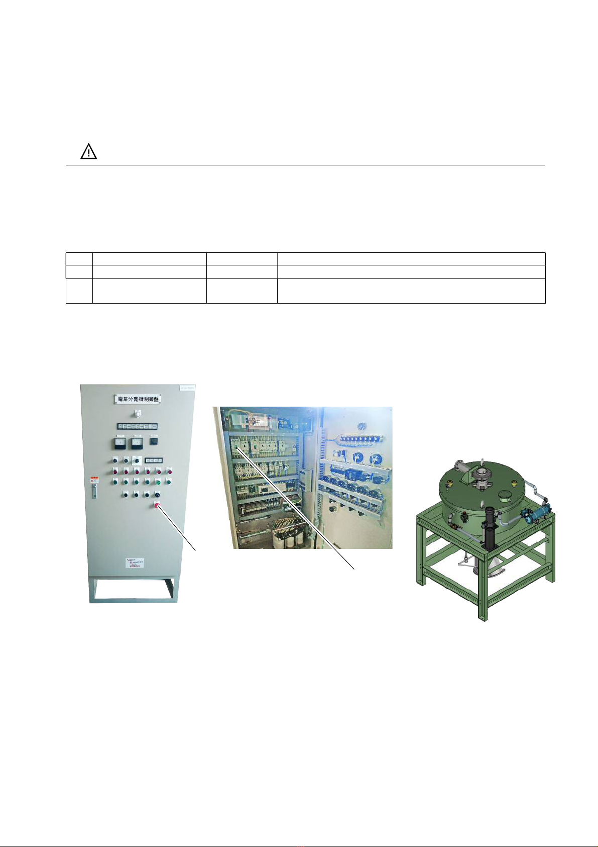
1.2.1 PROTECTIVE DEVICE
Name Location Function
①
Main breaker Control panel Stop the unit immediately. (Turn off Main breaker)
②
Emergency stop button Control panel Stop the unit immediately. (Push the Emergency stop
button)
1.2.2 LOCATION OF THE PROTECTIVE DEVICE
AT-CG-150HHH-1
②
①

- 1. Safetyinstruction
1-6
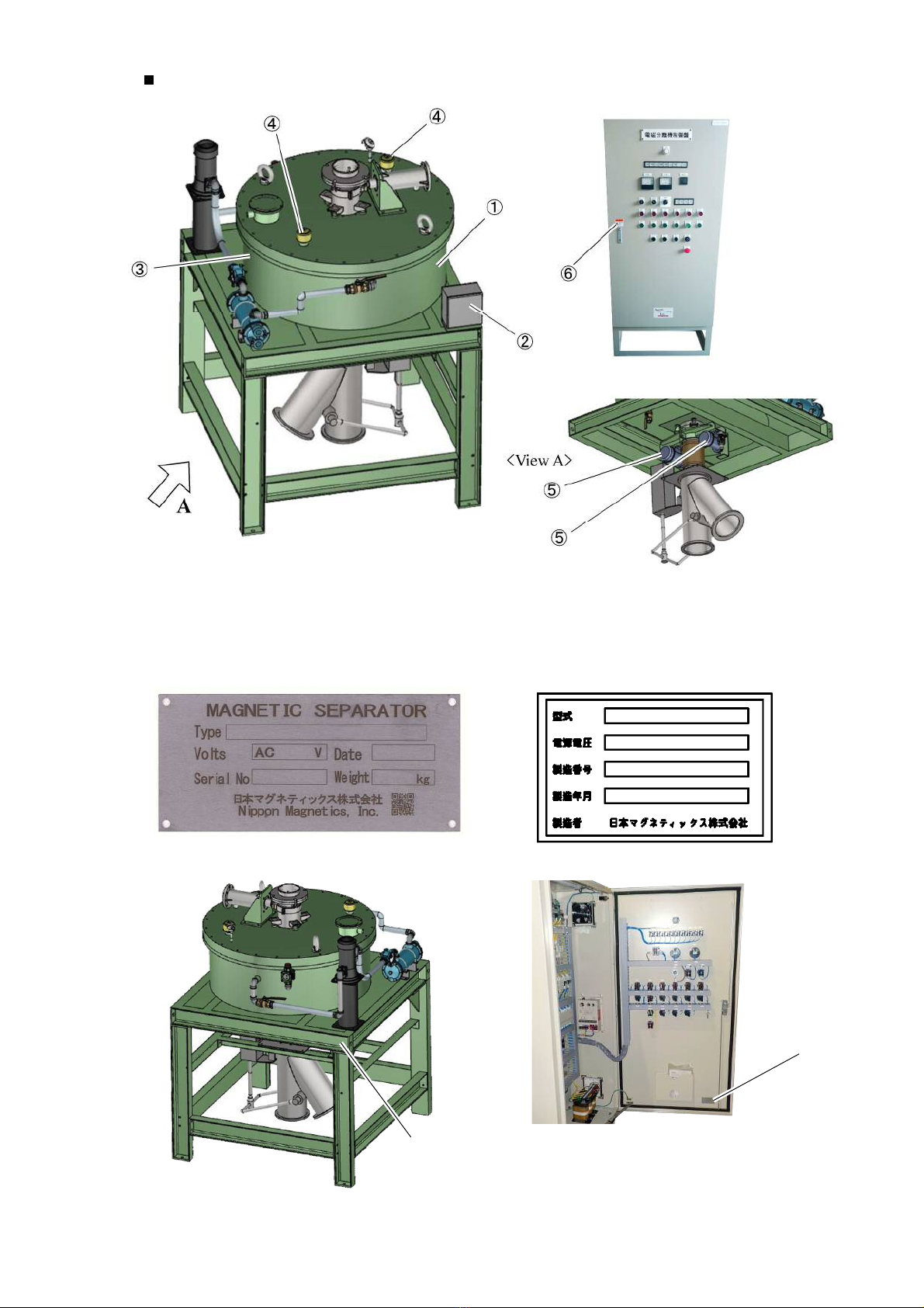
1.3 WARNING LABEL AND NAME PLATE
The following warning label and name plate are attached to the Unit (CG) and equipment.
Be sure to understand the contents of the warning label and nameplate before starting operation.
When warning label become unreadable due to contamination or damage.
NMI supply a new label. Please contact to NMI
1.3.1 WARNING LABEL
①
Warning
:
magnetic caution
②
Warning
:
Electric shock
③
Warning
:
Signal
④
Caution
:
Air breather
⑤
Caution
:
Rotating object
⑥
Warning
:
Electric shock
- 1. Safetyinstruction -
1-7
Location of Warning label
1.3.2 NAME PLATE
The following nameplates are attached to the equipment and control panel.
When making an inquiry, confirm the Model and Serial number on the name plate.
①②
②
①

- 1. Safetyinstruction
1-8
M EM O :
- 2. Overview -
2-1
2.
OVERVIEW
This Magnetic separator has a structure that efficiently concentrates the magnetic flux generated
inside the equipment to create a high magnetic flux density and is free from magnetic leakage. In
addition, this electromagnetic separator is capable of efficiently removing fine iron powder from
powdery raw materials by passing through a magnetized screen while dispersing fine powder with
poor fluidity by arranging a multi-layered screen with its tip at an acute angle into a cylindrical
interior and giving them fine vibrations.
AT-CG type is equipped with an iron powder auto-discharge device. By setting the timer, the
automatic iron powder discharge device is activated, and the removed iron powder can be
periodically discharged outside the device without stopping the operation of unit.
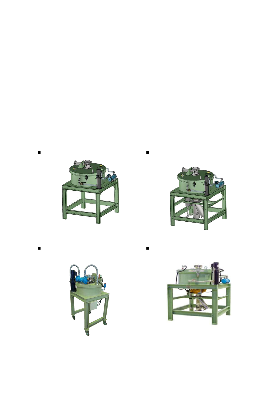
2.1 UNIT
The following types of CG type electromagnetic separators are available.
Electromagnetic separator CG
CG-150HHH-1
Electromagnetic separator AT-CG
(
Automatic discharging device
)
AT-CG-150HHH-1
Electromagnetic separator CG-MINI
(
Compact type
)
CG-150mini
Electromagnetic separator CG-X
(
High magnetic force type
)
AT-CG-150X-1
- 2. Overview -
2-2
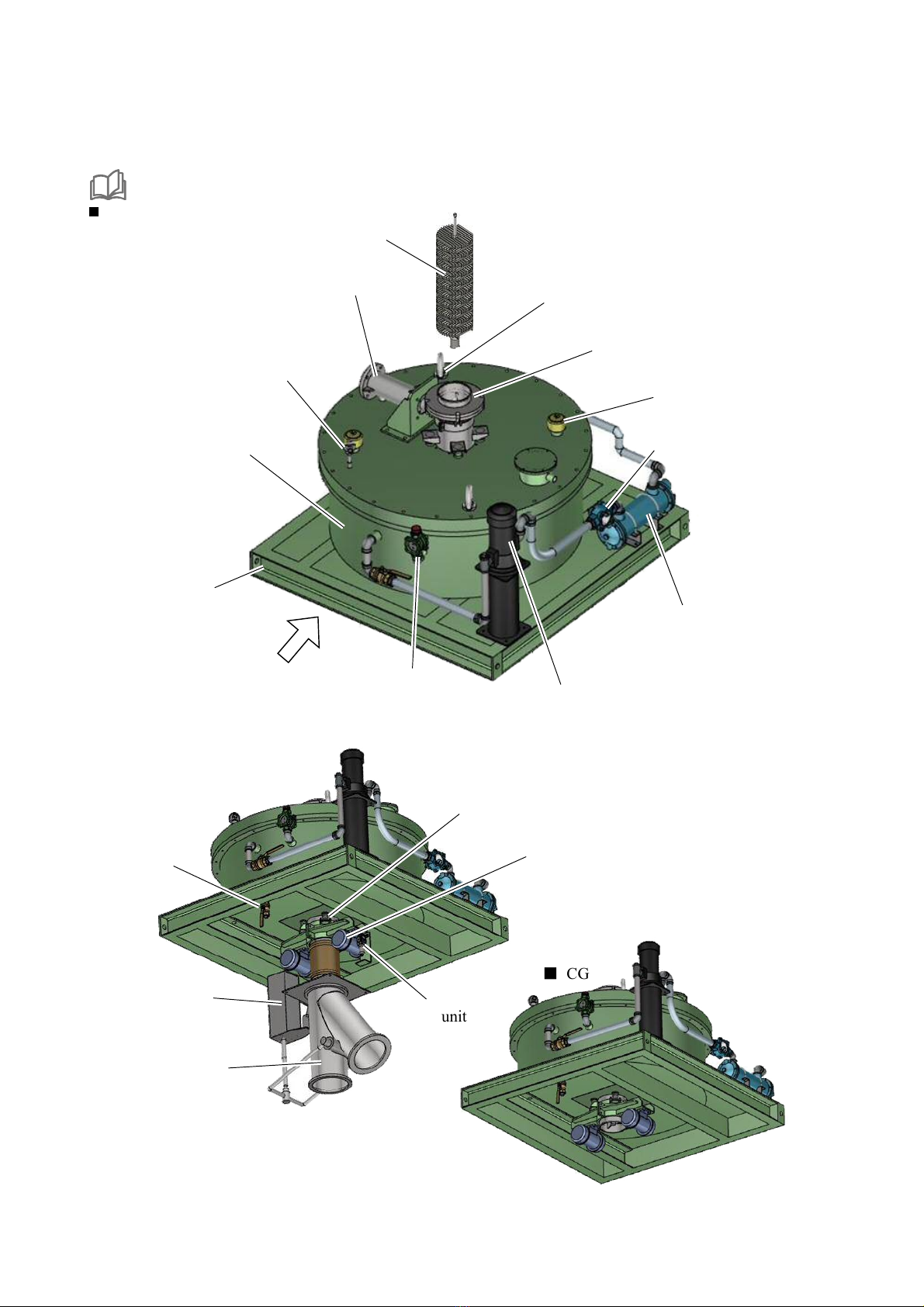
2.2 PARTS
The figure below shows a general shape. The shape may differ slightly from the delivered machine depending
on the specifications.
Refer to the delivery drawing for details.
AT-CG
①
Screen
⑦
Air breather
⑧
Screen case
⑩
Oil coole
r
⑪
Flapper sight glass
⑥
Oil pump
⑮
Mag
H
ammer
(
option
)
②
T
hermometer
③
Coil case
④
Frame
A
<
View A
>
⑤
Oil gauge
Oil inlet
⑫
Drain valve
⑬
Spring
⑭
Vibrator
⑨
Eye
bolt
⑰
Damper chute
⑱
Air cylinder
⑯
FR unit
■
CG

- 2. Overview -
2-3
2.3 FUNCTION
Name of parts Function Qty
①
Screen Magnetizes the screen to attract magnetic material.
When delivered, it is set in the screen case.
1set
②
Thermometer Insulation oil temperature sensor. 1
③
Coil case Electromagnetic coils and insulation oil are
contained in the case.
1
④
Frame 1
⑤
Oil gauge
Oil inlet
Check the amount of insulation oil.
Refilling the insulation oil from this inlet.
1
⑥
Oil pump Insulation oil in the coil case is circulated outside,
this pump for cooling with an oil cooler and
returning it back into the coil case again.
1set
⑦
Air breather Expanded warm air through out from the inside of
the coil case.
Refilling the insulation oil.
2
⑧
Screen case Set the screen into the Screen case.
Material passes through the Screen case.
1
⑨
Eyebolt Used to lift the machine with crane 1set
⑩
Oil cooler There are two cooling methods: Water
cooled type and Air cooled type
1set
(
Water cooled
)
Cooling water flows through the tubes in the oil cooler to indirectly cool the insulation oil.
(
Air cooled
)
Oil flows inside the radiator and air is blown to the outside of the radiator to indirectly cool the
insulation oil.
⑪
Flapper sight glass Check the flow direction and flow rate of the
insulation oil.
1
⑫
Drain valve When replacing the insulation oil, open this valve to
drain the oil.
1
⑬
Spring The vibration of the vibrator is transmitted to the
screen.
1set
⑭
Vibrator Vibrates the screen case to prevent powder
accumulation.
2
⑮
MagHammer (Option) Hit the screen case and prevent the accumulation of
powder on the screen.
1
⑯
FR-unit (AT-CG) Adjust the air pressure. 1
⑰
Damper chute (AT-CG) The damper chute be separated the product and iron
powder with timer control.
1
⑱
Air cylinder (AT-CG) By pushing and pulling the piston rod with air, the
damper position is changed.
1

- 2. Overview -
2-4
2.4 SPECIFICATION
2.4.1 SPECIFICATION (MAIN UNIT)
Main unit (CG)
Coil case
:
SS400
Screen case
:
SUS304
Screen
:
SUS430
+
SUS304
Joining method
:
Adjust with a flexible material.
Other
:
Refer to the delivery drawing for details.
Outline of structure
1. Several doughnut-shaped coils are placed in the coil case, and spacers are provided between the
coils for cooling oil. This coil generates a magnetic field inside the screen case to magnetize the
screen.
2. Insulation oil is contained inside the oil case, although it is not completely sealed, the ingress of
dust and other substances into the oil is prevented by an air breather on the coil case.
in addition, the expansion of the coil and insulation oil due to temperature rise is adjusted with an
air breather.
3. This unit uses a cooling system to keep the coil temperature. Normally, cooling is performed by
the water cooled method. If water cannot be used, cooling is performed by air cooled method.
Note: Some types do not have a cooling method.
This manual suits for next models
21
Table of contents


