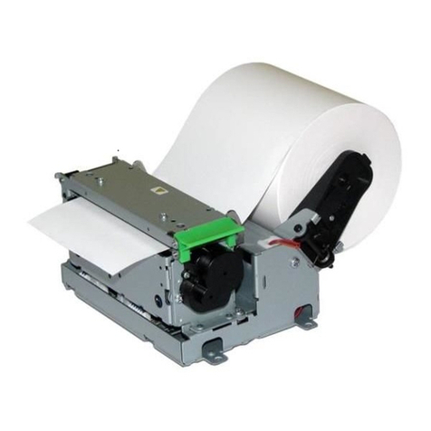
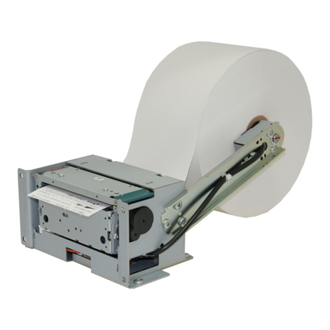
Nippon Primex NP-2411 User manual

D-F0472 NP-2411/3411 Product Specifications Rev.1.80
Product Specifications
2 inch / 3 inch High Speed KIOSK Printer
NP-2411
NP-3411
Revision 1.00 2008.08.09 1st edition
Revision 1.80 2012.01.26 9th edition
All specifications described are subject to change without prior notice.
Though we made assurance doubly sure to write this product specifications,
Please contact us if you find any mistakes and erroneous omitting.
Nippon Primex Inc
●Head Office
1-5-12 Unoki, Ohta-Ku, Tokyo 146-8650 Japan
TEL: +81 3 3750 5817 FAX: +81 3 3750 4555
E-mail: [email protected]
URL: http://www.primex.jp
Spec. №D-F0472

D-F0472 NP-2411/3411 Product Specifications Rev.1.80
Revision History
Description
Rev. N
o Page Item Contents of change
Approval Person in
charge
1.00 1 New release Asahina Abe
2008.05.12 2008.05.09
1.10 2 Added functions Added : Receive buffer Asahina Abe
remaining size auto-return 2009.02.17 2009.02.17
(USB)
1.20 3 Added functions Added :QR Code(Model 2) Asahina Abe
2009.03.02 2009.03.02
1.21 4 Added functions Added : F/W 1.20 Asahina Abe
2009.10.25 2009.10.25
1.30 4 Added functions Added : Rev.”02A” Asahina Abe
(Added : F/W 1.20) 2010.10.27 2009.10.26
1.40 5 Added functions Added : F/W 1.50 Asahina Abe
2010.09.14 2010.09.14
1.50 6 Added functions Added: GS I n m Ashahina Abe
2010.10.25 2010.10.25
1.60 7 Separate volume Asahina Abe
2010.12.22 2010.12.22
1.70 8 Frontpage Company (Old) Nichipri Industria Gonmori Abe
name change l Inc. 2011.04.28 2011.04.28
(New) Nippon Printer
Engineering, Inc.
1.80 9 2 Feature 9) Partial change Gonmori Abe
4 Option 2)added base plate 2012.01.27 2012.01.26
7 Paper thickness Modified
8 3)Recommended Changed paper thickness
Thermal Paper of TF50KS-E2D
15 Paper thickness Modified
16 2)Sensor position *Added “For prevention o
f malfunction…”
32 How to shift to Deleted the unnecessary
setting mode 6 part
Command Reference
2、16 Printer Information Added: 14
Transmission
(ESC s n)
3、22 GS U Dn Addition
(USB serial numbe
r setting)

D-F0472 NP-2411/3411 Product Specifications Rev.1.80
PRECAUTION
Please Read Carefully Before Using the Product
Handling the product in a wrong way may decline its performance and also damage the product. Please
read the notes below before handling the product. Also, please sufficiently alert the user.
[FAILURE PRECAUTIONS]
Please comply with following in order to use for many years to come and prevent troubles before
happens.
STATIC-ELECTRICITY;
●Static discharge prevention or body grounding must be made for installation and removal of the product
to prevent damage of heating element and IC etc. Connect it to the earth ground for ESD measures.
HANDLINGS;
●DO NOT apply excessive force to the input terminals.
●Use both hands when holding the product in order to prevent from dropping.
●Since it will cause damage of the heat elements, DO NOT scrabble or give impact to thermal head with
sharp edge object or any hard materials.
INSTALLATION;
●This product is NOT protected against dust or dirt. If used in harsh environment like at dusty place, the
thermal head may get damaged or paper feed may not run properly.
●When cooling the product with a fan, keep the air exhaust slit away from the printer’s paper exit area so
that dust or dirt may not get in the thermal head. It will be a cause for premature failure.
●This product is equipped with an infra-red reflection sensor. The product must be installed where there
is NO direct sun light/infra-red light coming in, as otherwise, the sensor would not function properly.
●The product should NOT be installed where it could be exposed to static electricity easily, strong
vibration, electromagnetic field, corrosive gas, rain, fog and direct sunlight.
MOVEMENT;
●Avoid printing with no paper loaded. It can damage thermal head and also shorten its life-time.
●DO NOT absolutely open the upper cover while printing and/or cutter operation. It may damage thermal
head and cutter.
●DO NOT pull out the paper with the upper cover closed.
●DO NOT block the paper outlet while print operation. Also, DO NOT grab the paper while print operation.

D-F0472 NP-2411/3411 Product Specifications Rev.1.80
[SAFETY PRECAUTIONS]
Please comply the follows in order to use for many years to come and prevent troubles before happens.
●Turn OFF the power before connecting or removing connectors. When disconnecting, handle with the
connector body and DO NOT pull out by a cable.
●The product is NOT protected from water or dew drop. DO NOT put water to the product nor handle it
with wet hand because it may cause damage, heating, firing by short circuit.
●In order to prevent excessive current, please add an electrolytic capacitor and a fuse (refer to power
supply specifications for details) to external 24V power line.
●Please DO NOT disassemble or modify the product.
●In case of disposal, please follow the regulations or rules of the local authorities.
●Recommend a power supply in conformity with LPS standard.
●Turn OFF the power when not using for a long time.
●Regardless of during movement or stop of the cutter, DO NOT touch the cutter blade.
[QUALITY PRECAUTIONS]
Please comply the follows in order to use for many years to come and prevent troubles before happens.
DATA;
●Movement when sending undefined control codes and commands to the product is not guaranteed.
●Since the print feed may jumble between the first 1 – 4 dot lines with such a print program that the print
and paper feed gets interrupted temporarily in state of printer’s data queuing from the host device, be
cautious when graphics and the like are included in the print data.
PRINT MOVEMENT;
●The print may jumble at the first 1-2 dot right after the paper cut action.
●DO NOT touch the heating element part of the thermal head, since it could degrade the print quality due
to soil.
●In case of using print papers other than those specified in this document, print quality and lifetime of
thermal head may not reach the level guaranteed by the manufacturer.
●DO NOT pull out the paper while the printer is in motion of printing, paper feeding or cutting. When
removing the partially cut paper or perforated paper, pull it to either right or left direction without too
much force.
●Continuous motor running for a long time generates heat and may affect the printer performance. To
avoid the case, it is necessary to limit the continuous motor running time to 6 minutes at maximum with
the same interval time for each operation.
●Motor may produce heat by continuously driving cutter motor for a long time and it may not perform
necessary functions. Make sure to follow cutter tolerable frequency.
●Set the paper straightened with no slack.
●A part of this product is made from coated steel plate. It does not affect the product’s quality and
performance at all even if the cut face of the steel plate get rusty after a long time period.

D-F0472 NP-2411/3411 Product Specifications Rev.1.80
[OTHER PRECAUTIONS]
●This product is designed to use with general electronic devices. (Computer, PC, OA etc.) This product is
not designed and guaranteed to use with devices that require extremely high quality and reliability, also
to use with devices that those failures may directly endanger human body and life. (Atomic power
control device, aerospace aircraft device, transportation device, traffic signal device, ignition control
device, medical device and various safety devices: hereafter called as “Specific application”.) Users
shall take full responsibility for using with such specific application.
●DO NOT conduct operation that is not suggested in this instruction. It may cause accident or failure.
●Data can not be long-term stored, permanently stored and saved since it is basically evanescent.
Nippon Primex Inc is not responsible for any damages of data deletion or lost income due to breakdown,
repair or inspection.
●When selecting RTS/CTS in serial flow control, make sure to connect RTS/CTS signal to the flow
control signal of the host side, otherwise flow control will not function and may cause garble character or
printing disarray.
●The coverage of warranty is limited within the product itself, Nippon Primex Inc is NOT responsible for
anything induced by the defect of the product and DO NOT pay for any compensation that may occur.

D-F0472 NP-2411/3411 Product Specifications Rev.1.80
Table of Contents
1. Overview ·············································································································································1
1.1 Overview ········································································································································· 1
1.2 Feature············································································································································ 2
1.3 Configuration··································································································································· 3
1.4 Options············································································································································ 4
2. Specifications ······································································································································5
2.1 Basic Specifications························································································································· 5
2.2 Paper Specifications························································································································ 7
2.3 Printing Area·································································································································· 10
2.4 Cutter Specifications······················································································································ 15
2.5 Sensor Position ····························································································································· 16
2.6 Power supply Specification············································································································ 17
2.7 Reliability Specifications ················································································································ 18
2.8 Environment Specifications ··········································································································· 19
2.9 Regulations ··································································································································· 19
2.10 External Dimensions ··················································································································· 20
3. Configurations ···································································································································23
3.1 Interface [USB(V2.0 FULL SPEED)] ····························································································· 23
3.2 Interface[Serial(RS-232C compliance)] ························································································· 24
3.3 Connector Signal Table ················································································································· 25
4. Functions···········································································································································27
4.1 Function Setup······························································································································ 27
4.2 Error Handling······························································································································· 34
4.3 Buffer Full Print······························································································································ 34
4.4 Driving Selection ··························································································································· 35
4.5 How to switch Print of Full
size / Half size ·················································································· 35
4.6 Operation Panel ···························································································································· 36
4.7 How to set Roll Paper···················································································································· 37
4.8 How to remove the remaining paper, jammed paper. ···································································· 40
4.9 How to clean thermal head.··········································································································· 41
Appendix (Please refer to the following documents for commands and code tables.)
・Command Reference [NP-2411/NP-3411] (D-F0472)
* Command reference includes the following code tables other than commands.
Domestic Character Code Table, Overseas Character Code, Code Page 858, International
Character Code Table, Code Page 1253,
Code Page 1250, Code Page 1251, Code Page 1252, Code Page 1254
・Kanji Code Table [JIS C 6226・1983] (D-F10068)
・Chinese Code Table [GB18030-2000] (D-F10069)
・Korean Code Table [KS X1001-1992] (D-F10070)

D-F0472 NP-2411/3411 Product Specifications Rev.1.80 1
1. Overview
1.1 Overview
This printer is categorized as follows.
NP-3411
D-
*
(1) (2) (3)
(1) Paper size (default setting)
2:2 inch(standard:58mm)
3:3 inch(standard:80mm)
(2) Interface(default setting)
Standard
D:SERIAL(RS232C),USB(V2.0 FULL SPEED)Dual, Selection
Specification possibly considered for mass production
U:USB(V2.0 FULL SPEED)only
(3) OEM(comply with separate delivery specification)
No marking : standard model

D-F0472 NP-2411/3411 Product Specifications Rev.1.80 2
1.2 Feature
This model mounts our printer mechanism also module printer that increases operability. The only
necessary built-in action to each device to activate is power supply (DC24V) and data input also
enables free retrofit of user-side.
1. Extremely small sized, light weight and especially low height offers free design for various
embedded devices.
2. Wide range of Operating Environment
3. Low cost
4. Thick paper is printable.
5. High Print Speed, High Print Quality
6. Interface corresponds to SERIAL and USB.
7. Various 1D bar-codes are available.
8. Enables to apply to various kinds of applications
9. Driver(Windows) XP(32bit)/ Vista(32,64bit) / 7(32,64bit) / CE5.0 / CE6.0 Linux(Sample)
10. Easy to write/rewrite F/W (*3) by adopted flash memory. Also, 3 patterns of NV bit image can be
saved and registered.
11. Multi language
12. Enable to control an optional paper feeding equipment. (Presenter)
13. Simple and easy paper loading by “Auto Paper Loading” function.
14. Easy maintenance due to a complete openable mechanism of a paper path.
Easy to remove jammed paper.
15. Mounting newly developed clamping type paper holder “PH-10”(see *NOTE1 below)
I. Roll paper holder with one-touch easy loading and certain near end detection.
II. Besides ID12mm of roll paper, it enables to use roll paper of ID25.4mm by attaching
separately available paper support.
III. Besides ex-factory setting of near end detection is OD22mm, it enables to change to
24mm dia. by adjusting sensor position.
*NOTE1) Refer to [2. 2 Paper Specifications] for details.
16. Enable to support a large paper holder (φ200mm) by attaching optional universal paper holder
17. Enable to flash the edge part of the paper exit by attaching LED bezel
18. Selectable options*2
*1 Refer to [2.2 Paper specifications] for details.
*2 Refer to [1.4 Options] for details.
*3 [F/W] refers to [firmware].

D-F0472 NP-2411/3411 Product Specifications Rev.1.80 3
1.3 Configuration
1) NP-2411D(standard)
Configuration
No Name Specifications Qty
NP-2411D
2 inch, USB and Serial(dual),
1 NP-2411D Power supply 2 pin 1 ○
The board equipped with Dip
Switch
2 Thermal roll paper W58xOD30(ID12)mm 1 ○
2) NP-3411D(standard)
Configuration
No Name Specifications Qty
NP-3411D
3 inch, USB and serial(dual),
1 NP-3411D Power supply 2 pin 1 ○
The board with DIP Switch
2 Thermal roll paper W80xOD30(ID12)mm 1 ○
3) NP-2411U (possible specification for mass production)
Configuration
No Name Specifications Qty
NP-2411U
2 inch, USB,
Power supply 2 pin,
1 NP-2411U
The board with DIP switch
1 ○
2 Thermal roll paper W58xOD30 (ID12)mm 1 ○
4) NP-3411U (possible specification for mass production)
Configuration
No Name Specifications Qty
NP-3411U
3 inch, USB,
Power supply 2 pin
1 NP-3411U
The board with DIP switch
1 ○
2 Thermal roll paper W80xOD30(ID12)mm 1 ○
Printer main body (NP-3411 or NP-2411)........... 1 unit
Accessory
* Thermal roll paper (sample)............... 1roll

D-F0472 NP-2411/3411 Product Specifications Rev.1.80 4
1.4 Options
1)Paper support
No Name Specifications Qty
1 Paper support Inner core dia25.4mm 2
Paper support
・Attachment for inner core diameter of 25.4mm..... 2pcs
2)Base plate
A base plate enabling to cut off the discharge paper and front operation is available.
Please refer to [Products specification D-F10102] about how to mount it.
Component parts
No Name Specification Quantity BasePlate_2 BasePlate_3
1 P083_BasePlate_2 Base plate for NP-2411 1 ○
2 P083_BasePlate_3 Base plate for NP-3411 1 ○
3 ScrewPH(ST)M3x6
Small screw S tight M3x6
(Screws for attachment to
a printer)
2 ○○
This printer is ready for below options other than the above 1) and 2)
Please read carefully each product specifications because there are conditions or restrictions in
order to use safely.
3) Power Supply PS8
Power Supply Adaptor is prepared
Please read carefully product specifications D-F10058 for consideration.
4) BEZ-320/330 bezel with function to emit LED light
2 inch or 3 inch LED bezel is available.
Please read carefully product specification D-F10059 for consideration.
5)Bezel BEZ-220/221/230/231
2 inch or 3 inch, bezel including paper-out sensor or not including.
Please read carefully specification D-F10056 for consideration.
* When using bezel, make sure that paper length is not less than 55mm.
(In case paper length is less than 55mm, it is not easy to pull paper
frombezel.)
6)Presenter NPT-306
Paper retraction presenter
Please read carefully specification D-F0482 for consideration to use.
7)Paper jumbo holder UPH-LA
Universal paper jumbo holder
Please read carefully specification D-F10060.

D-F0472 NP-2411/3411 Product Specifications Rev.1.80 5
2. Specifications
2.1 Basic Specifications
№Specifications NP-2411 NP-3411
1 Head 1: Print method Thermal line dot
2: Total dots/line 432 dots 576 dots
3: Dot density 8dot/mm
4: Printing width(max) 54 mm 72 mm
2 Printing 1: Printing speed (MAX)*NOTE1 MAX.150mm / sec
Conditions Head temp. at over 35ºC, buffering method,
optimized driving print ratio 50% or less.
*except communication time
2: Max. print digit
Font A (12 × 24) 36 digits 48 digits
Font B (9 ×17) 48 digits 64 digits
Kanji (24 × 24) 18 digits 24 digits
3: Line feed pitch 0.125mm
3 Characters 1: Character size
Font A (12 × 24) 1.50 × 3.00mm
Font B (9 × 17) 1.13 × 2.13mm
Kanji (24 × 24) 3.00 × 3.00mm
2: Character types
Japanese JIS C 6226 1983 (Full size)
Japanese Code (Half size)
Foreign Code (Half size)
Code Page 858 (Half size)
International character set (Half size)
Korean KS X 1001:1992 (Full size)
Katakana character set (Half size)**NOTE2
Extended Graphic character set (Half size)**NOTE2
Code Page 858 (Half size)
Chinese GB18030-2000 (Half / Full size)
Greek Code Page 1253 (Full size)
Polish Code Page 1250 (Half size)
Russian Code Page 1251 (Half size)
Scandinavian Code Page 1252 (Half size)
Turkish Code Page 1254 (Half size)
3: Character decoration Double width
Double height
Quadruple
Enhanced print
Double strike
Inverted
90°clockwise rotation
Underline
4: Line spacing (default) 4.25mm (1/6 inch)
*NOTE 1) Printing speed depending on condition.
**NOTE 2) KS X 1001:1992 built-in font.

D-F0472 NP-2411/3411 Product Specifications Rev.1.80 6
№Specifications NP-2411 NP-3411
4 Print mode 1: Line mode ANK mode
Barcode mode
Bit image mode
Buffering mode
5 Barcode 1: 1-D barcode UPC-A
UPC-E
JAN-13 (EAN-13)
JAN-8 (EAN-8)
CODE39
ITF
CODABAR
CODE128
2: 2D barcode*NOTE4 QR code model 2
6 Interface 1: SERIAL (dual type) RS232C compliance
2: USB(dual type, U type) V2.0 FULL SPEED compliance
7 Auto cutter 1: Cutting mode Full / Partial cut
*selectable by command
8 Buffer receipt Approx. 15K bytes
9 Alarm display ALARM LED
10 Operation switch FEED switch
RESET switch
11 Outer dimensions (w/o connector, paper) 103.6 (W) x 123.5 (D) 124.6 (W) x 123.5 (D)
× 77.3 (H) mm X 77.3 (H) mm
12 Weight (w/o paper) Approx. 500g Approx. 560g
13 Mounting***NOTE3 Horizontal Horizontal
14 Package 1: Individual carton size 224 (W) x 169 (D) 224 (W) x 189 (D)
X 168 (H) mm x 168 (H) mm
2: Individual carton weight 800g 900g
3: Master carton size 531 (W) x 472 (D) 591 (W) x 472 (D)
x 375 (H) mm x 375 (H) mm
4: Master carton weight 11.6kg 13.0kg
(includes 12pcs) (includes 12pcs)
***NOTE 3) Mounting shall be placed horizontally. Please contact us for different mounting.
****NOTE 4) Only available for F/W Ver.1.30 or later.

D-F0472 NP-2411/3411 Product Specifications Rev.1.80 7
2.2 Paper Specifications
1) Paper width / thickness
2inch 3inch
Paper width 58/60-1mm 76/80-1mm
Paper thickness 59~150μm
[Caution]
* DO NOT change paper width from narrow to wide during operation.
( There is possibility of thermal head damage when scraping
against platen directly.)
* Please consult with us when using paper width of 60 and 76mm .
( All of the paper width is set as default setting.)
2) Paper shape
* Roll paper shape
Roll size (Max.) Thickness Inner core Outer core
83mm dia 65~85μm 12.0mm dia 18.0mm dia
83mm dia 100~150μm 25.4mm dia φ33.4mm
[CAUTION]
* Use standard paper holder PH-10.
(Please ask us when you use more than diameter 84mm. )
* Core width is the same as paper width.
* Use an optional paper support for roll paper of axis inner core DIA25.4mm.(Figure)
[Conditions of using thermal paper]
・Use thermal paper
・Do not stick end of paper with glue and scotch tape.
・The core of paper roll should not be deformed.
・The core should not be stuck out over the side of the paper roll.
・DO NOT use paper rolls stored on condition of high temperature and humidity.
・Paper roll is not loosened.
・Printing surface shall be outer surface. Involute paper is not applicable.
・Sufficiently confirm when using preprinted paper. Especially, beware of the
print side surface because there is a paper sensor equipped.
・DO NOT use long-term stored paper roll because it may not perform satisfactory
print quality.
Dia.25.4 Attachment
Dia.12

D-F0472 NP-2411/3411 Product Specifications Rev.1.80 8
3) Recommended Thermal Paper
P/N Thickness Maker
PD160R 0.075mm OJI Paper Co.
PD450-145 0.145mm OJI Paper Co.
PD150R 0.075mm OJI Paper Co.
PDC600-145 0.145mm OJI Paper Co.
TF50KS-E2D 0.059mm NIHON Paper Co.
[CAUTION]
*Since printing quality will degrade effecting by circumstances of temperature and humidity
etc., confirm printing quality before setting printing density. Printing density can be set by
switching memory switch MS2-8 or using command of [Print Density Setting] «GS ~ n»
*Printing at high print ratio under low temperature or high humidity environment cause
printed paper to be tainted or dew drop due to vapor occurred from the roll paper. Beware
water not to drop to the thermal head part. This may lead thermal head’s electrolytic
corrosion.
In case of dew drop, turn OFF and wait until the dew disappears.
*Select thermal paper which has a low level of Na+ ion, K+ ion and CI- ion when using
non-recommended thermal paper and should be well evaluated in reliability.

D-F0472 NP-2411/3411 Product Specifications Rev.1.80 9
4) Paper Holder(Standard:PH-10)
Name Paper width MAX OD Axis core OD to NE sensor
ID12.0mm
OD18.0mm DIA22.0±2.5mm
PH-10 -DIA83mm I D25.4mm*NOTE1
OD33.4mm DIA37.0±2.5mm **NOTE2
*NOTE1) *Use an optional paper support for roll paper of axis inner core DIA25.4mm.
**NOTE2) Change position of near end sensor with using roll paper of inner core DIA25.4mm.
(see figure below)
1) Change of NE (near end) setting
Replace or loosen M2 screw and move near end sensor.
* Loosen M2 screw and slide near end sensor unit.
(A<->B,C<->D)
* Remove M2 screw and move near end sensor unit.
(Aor B <-> Cor D)
a) Axis inner core diameter 12.0mm
A position: Remaining OD22.0±2.5mm (default)
B position: Remaining OD24.0±2.5mm
b) Axis inner core diameter 25.4mm
Cposition : Remaining OD34.0±2.5mm
Dposition : Remaining OD37.0±2.5mm (Recommended position for OD33.4mm)
A B
NE sensor unit
C D
M2 Screw

D-F0472 NP-2411/3411 Product Specifications Rev.1.80 10
2.3 Printing Area
1) Code name
Code Name
A Print dot No
B Left margin
C Print area
D Right margin
E Paper width
2) Paper width and print area
A(dot) B(±1mm) C(±0.2mm) D(±1mm) E(-1mm)
Default
416 dots 3 mm 52 mm 3 mm 58 mm ○
432 dots 3 mm 54 mm 1 mm 58 mm -*1
2inch
432 dots 3 mm 54 mm 3 mm 60mm *2 -
560 dots 4 mm 69 mm 3 mm 76 mm*3 -*1
3inch
576 dots 4 mm 72 mm 4 mm 80 mm ○
*1: It is possible to set by turning on memory switch MS2-7(refer to 4.1.1. Memory
Switch ), however the right margin (D) will be 1mm, so that printing may be out
of range due to paper bias.
*2:When change paper width, Refer to [NP-2411 Change paper width 58mm→60mm]
*3:When change paper width, Refer to [NP-3411 Change paper width 80mm→76mm]
1dot 2dot Adot
0.125mm
B CD
E
FEED direction
Print Surface

D-F0472 NP-2411/3411 Product Specifications Rev.1.80 11
3) How to change paper width
[NP-3411 Change paper width 80mm→76mm]
Before change. Paper width 80mm(Default)
Move Guide and Paper holder.
* Power is OFF.
(1) Remove 2 screws printer outside.
(2) Pull PH-10 to arrow direction and remove plate.
* Do not bend plate.
(3) Remove barrier.
(4) Move Guide.
* Note : DO NOT float or bend of Guide, and DO NOT loose screw.
Remove screw(2 places)
Small screw M3
Remove plate(2 places)
PH-10
Barrie
r
Push plate outside lightly and remove barrier.
Remove barrier(2 places)
Guide
Pa
p
er holde
r
Interspace inside Guide No interspace between
Paper holder and Guide.
Interspace
Remove screw.(1 place)
Small screw M2x4 No.0
Open thermal
head cover
and remove
Guide.
Paper width 76mm Screw
Paper width 76mm Boss hole
Paper width 76mm Guide hole
Guide
Fix Guide with holding
on the point of 76mm.
(1 place)
Small screw M2x4
No.0

D-F0472 NP-2411/3411 Product Specifications Rev.1.80 12
(5) Attach barrier.[(3) Removed barrier]
* Note the direction of barrier.
(6) Attach plate.[(2) Removed plate]
* Attach plate from the backward I/F connector side.
* Do not tuck down cable.
(7) Attach screw of printer outside.[(1) Removed screw]
(8) Move paper holder.
* DO NOT float or bend of paper holder, and DO NOT loose screw.
After changed. Paper width 76mm
Barrie
r
Push
p
late outside li
g
htl
y
and attach barrier.
Insert steadil
y
.
(
2
p
lace
)
Let out cable.
Do not get under barrier
or do not tuck down.
Barrier allocated upper
Fit up plate.(4 places)
Remove screw(2 places)
Small screw M3
Remove screw(1 place)
Small screw M3
Paper width 76mm
Screw hole
Paper width 76mm
Boss hole
Pa
p
er width 76mm Boss hole Fix paper holder with
holding on 76mm point
(1 place)
Small screw M3
Interspace outside Guide Interspace between
p
a
p
er holder and
p
late

D-F0472 NP-2411/3411 Product Specifications Rev.1.80 13
[NP-2411 Change paper width 58mm to 60mm]
Before change. Paper width 58mm(Default)
Move Guide and Paper holder.
* Power is OFF.
(1) Remove 2 screws printer outside.
(2) Pull PH-10 to arrow direction and remove plate.
* Note : do not bend plate.
(3) Remove barrier.
(4) Move Guide.
* Note : DO NOT float or bend of Guide, and DO NOT loose screw.
Remove screw (2 places)
Small screw M3
Remove plate(2 places)
PH-10
Remove barrier(2 places)
Barrie
r
Push
p
late outside li
g
htl
y
and remove barrie
r
.
Guide
Chase outside guide
P
ape
r H
o
l
der
Interspace between plate
and
p
a
p
er holde
r
Remove screw(1 place)
Small screw M2x4 No.0
Guide
Open thermal head
cover and
remove Guide
Paper width 60mm
Screw hole
Paper width 60mm Boss hole
Paper width 60mm Guide hole
Fix Guide with holding
on the point of
60mm.(1 place)
Small screw M2x4
No.0
No interspace

D-F0472 NP-2411/3411 Product Specifications Rev.1.80 14
(5) Attach barrier.[(3) Removed barrier]
* Note the direction of barrier.
(6) Attach plate.[(2) Removed plate]
* Attach plate from the backward I/F connector side.
* Do not tuck down cable.
(7) Attach screw of printer outside.[(1) Removed screw]
(8) Move paper holder.
* DO NOT float or bend of paper holder, and DO NOT loose screw.
After changed. Paper width 60mm
Remove screw(2 places)
Small screw M3
Fit up plate.(4 places)
Barrie
r
Push
p
late outside li
g
htl
y
and attach ba
r
rier.
Let out cable.
Do not get under barrier
or do not tuck down.
Insert steadily.(2 points)
Barrier allocated upper.
Remove screw (1 place)
Small screw M3
Paper width 60mm
Screw hole
Paper width 60mm Boss hole
Paper width 60mm Boss hole
Fix paper holder with
holding on 60mm point
(1 place)
Small screw M3
Interface inside Guide. Paper holder is
outside.
Other manuals for NP-2411
1
This manual suits for next models
1
Table of contents
Other Nippon Primex Printer manuals
Popular Printer manuals by other brands
Panasonic
Panasonic Network Printing DP2000/2500 Setup guide
Epson
Epson TM-TM88V-i Technical reference guide
DNP
DNP DS40 Repacking guide

Canon
Canon imageRUNNER ADVANCE DX C357iF Service guide
Brightek
Brightek E30 Quick install
Epson
Epson Stylus COLOR 480/480SX - Stylus Color 480SX Ink Jet... Installation & operation
