Nippon Primex NP-K3053 Installation instructions

Specs №D-F10072
Product Specifications
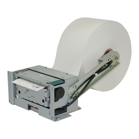
«24V KIOSK Printer with simple presenter»
N P – K 3 0 5 3
N P – K 2 0 5 3
Revision 1.00 2011.03.09 1st edition
*Since this product is under development, specifications etc. described in this manual may change.
All specifications described are subject to change without prior notice.
Please contact us for double-checking if you find any descriptions unclear
or something which seems to be mistyped or mistranslated.
Nippon Primex Inc.
Head Office:
1-5-12 Unoki Ohta-ku Tokyo 146-8650 Japan
TEL :+81-3-3750-5817 FAX :+81-3-3750-4555
URL : http://www.primex.jp
D-F10072 NP-K3053/K2053 Product Specifications Rev.1.00

D-F10072 NP-K3053/K2053 Product Specifications Rev.1.00
Record of Revision
Descriptions
Rev. V page Item Content Approval SIC
1.00 1 New release Asahina Abe
2011.03.10 2011.03.09

D-F10072 NP-K3053/K2053 Product Specifications Rev.1.00
PRECAUTION
Handling the product in a wrong way may decline its performance and also damage the product.
Please read the notes below before handling the product. Since there are detailed precautions
described other than this section, please read this product specifications carefully before using
the product. Also, please sufficiently alert the user.
[FAILURE PRECAUTIONS]
Please comply with the following in order to use for many years to come and prevent troubles
before happens.
STATIC-ELECTRICITY;
• Static discharge prevention or body grounding must be made for installation and removal of the
product to prevent damage of heating element and IC etc. Connect it to the earth ground for
ESD measures.
HANDLINGS;
• DO NOT apply excessive force to the input terminals.
• Use both hands when holding the product in order to prevent from dropping.
• Since it will cause damage of the heat elements, DO NOT scrabble or give impact to thermal
head with sharp edge object or any hard materials.
INSTALLATION;
• This product is NOT protected against dust or dirt. If used in harsh environment like at dusty
place, the thermal head may get damaged or paper feed may not run properly.
• When cooling the product with a fan, keep the air exhaust slit away from the printer’s paper exit
area so that dust or dirt may not get in the thermal head. It will be a cause for premature failure.
• This product is equipped with an infra-red reflection sensor. The product must be installed
where there is NO direct sun light/infra-red light coming in, as otherwise, the sensor would not
function properly.
• This product should NOT be installed where it could be exposed to static electricity easily,
strong vibration, electromagnetic field, corrosive gas, rain, fog and direct sunlight.
MOVEMENT;
• Avoid printing with no paper loaded. It can damage thermal head and also shorten its life-time.
• Absolutely DO NOT manipulate platen release lever while printing and/or cutting movement. It
may damage thermal head or cutter.
• DO NOT block the paper outlet while print movement. Also, DO NOT grab the paper while print
movement.
• Although paper may slightly pass obliquely, there will be no problems in clamp and clamp
release movement.

D-F10072 NP-K3053/K2053 Product Specifications Rev.1.00
[SAFETY PRECAUTIONS]
Please comply with the following in order to use for many years to come and prevent troubles
before happens.
• Make sure to turn OFF the power of the product when connecting or disconnecting the
connector. Do not disconnect by pulling out the cable.
• This product is NOT protected from water or dew drop. DO NOT put water to the product nor
handle it with wet hand because it may cause damage, heating, firing by short circuit.
• In order to prevent excessive current, please add an electrolytic capacitor and a fuse (refer to
power supply specifications for details) to external 24V power line.
• Please DO NOT disassemble or modify the product.
• In case of disposal, please follow the regulations or rules of the local authorities.
• Use power supply in conformity with LPS standard.
• Turn OFF the power when not using for a long time.
• Regardless of during movement or stop of the cutter, DO NOT touch the cutter blade.
[QUALITY PRECAUTIONS]
Please comply with following in order to use without imparing performance for many years to
come and prevent troubles before happens.
DATA;
• Movement when sending undefined control codes and commands to the product is not
guaranteed.
• Since the print feed may jumble between the first 1 – 4 dot lines with such a print program that
the print and paper feed gets interrupted temporarily in state of printer’s data queuing from the
host device, be cautious when graphics and the like are included in the print data.
PRINT MOVEMENT;
• The print may jumble at the first 1-2 dot right after the paper cut action.
• DO NOT touch the heating element part of the thermal head with a finger or hand etc., since it
could degrade the print quality due to soil.
• In case of using print papers other than those specified in this document, print quality and
lifetime of thermal head may not reach the level guaranteed by the manufacturer.
• DO NOT pull out the paper while the printer is in motion of printing, paper feeding or cutting.
• Please keep the following limitations in order to prevent failure due to over heat of the paper
feed motor.
Usage environment temperature Permissible continuous
paper feed time Drive ratio Example of driving
25°C (normal temp) under 6 min. under 50% Continuous 2 min. Stop 2 min.
50°C (max.) under 3 min. under 30% Continuous 2 min. Stop 5 min.
• Continuous motor running for a long time generates heat and may affect the printer
performance. Make sure to follow cutter tolerable frequency. When using beyond this limitation,
cutter may break at the worst case.
• Set the paper straightened with no slack.
• A part of this product is made from coated steel plate. It does not affect the product’s quality
and performance at all even if the cut face of the steel plate get rusty after a long time period.

D-F10072 NP-K3053/K2053 Product Specifications Rev.1.00
[OTHER PRECAUTIONS]
• This product is designed to use with general electronic devices. (Computer, PC, OA etc.) This
product is not designed and guaranteed to use with devices that require extremely high quality
and reliability, also to use with devices that those failures may directly endanger human body
and life. (Atomic power control device, aerospace aircraft device, transportation device, traffic
signal device, ignition control device, medical device and various safety devices: hereafter
called as “Specific application”.) Users shall take full responsibility for using with such specific
application.
• DO NOT conduct operation that is not suggested in this instruction. It may cause accident or
failure.
• Data can not be long-term stored, permanently stored and saved since it is basically
evanescent. Nippon Primex Inc is not responsible for any damages of data deletion or lost
income due to breakdown, repair or inspection.
• When selecting RTS/CTS in serial flow control, make sure to connect RTS/CTS signal to the
flow control signal of the host side, otherwise flow control will not function and may cause
garble character or printing disarray.
• The coverage of warranty is limited within the product itself, Nippon Primex Inc is NOT
responsible for anything induced by the defect of the product and DO NOT pay for any
compensation that may occur.

Table of Contents
1. Overview··················································································································································· 1
1.1 Overview ········································································································································· 1
1.2 Features ·········································································································································· 2
1.3 ································································································································· 3Configurations
1.4 Option Parts ···································································································································· 3
2. Specifications············································································································································ 4
2.1 Basic Specifications························································································································· 4
2.2 Paper Specifications························································································································ 6
2.3 Print Area········································································································································· 8
2.4 Cutter Specifications························································································································ 9
2.5 Paper Sensor ································································································································10
2.6 Power Specifications ····················································································································· 11
2.6 Power Specifications ····················································································································· 11
2.7 Reliability Specifications ················································································································ 12
2.8 Environment Specifications ··········································································································· 13
3. Configurations ········································································································································ 16
3.1 Interface [USB(V2.0 FULL SPEED)]······························································································ 16
3.2 Interface [SERIAL (RS-232C compliance)]···················································································· 17
3.3 Connector Signal Details ··············································································································· 18
3.3 Connector Signal Details ··············································································································· 18
4. Functions ················································································································································ 19
4.1 Function Setting ···························································································································· 19
4.2 Error Handling ······························································································································· 24
4.3 Buffer Full Print······························································································································ 25
4.4 Drive mode Selection ···················································································································· 25
4.5 Print Selection of Full size / Half size····························································································· 25
4.6 Operation Panel ···························································································································· 26
4.7 How to set paper roll······················································································································ 27
4.8 How to remove the remained and jammed paper·········································································· 28
4.9 Cleaning Method ··························································································································· 29
4.10 Precautions upon installation······································································································· 30
4.11 Frame Ground ····························································································································· 31
Separate reference document (Please refer to document below for command and code page)
• Command reference [NP-K3053/NP-K2053] (D-F10072)
*The following code pages are described besides command in the command reference.
Domestic Character Code Table, Overseas Character Code Table, Code Page 858,
International Character Code Table, Code Page 1250, Code Page 1251, Code Page 1252,
Code Page 1254
• Kanji Code Table [JIS C 6226・1983] (D-F10068)
D-F10072 NP-K3053/K2053 Product Specifications Rev.1.00

D-F10072 NP-K3053/K2053 Product Specifications Rev.1.00
1
1. Overview
1.1 Overview
Basic model of this printer is categorized as follows.
NP- K
3
0
5
3
D
(1) (2)
- 0 0 0 -
*
(3)
(1) Paper width (Factory setting)
Standard
3 : 3 inch (80mm)
2 : 2 inch (58mm)
(2) Interface (Factory setting)
Standard
D : Dual Interface (SERIAL-RS232C and USB-V2.0 FULL SPEED) – select use
Conceivable specifications for production
U : USB (V2.0 FULL SPEED)
(3) OEM (Complies with separate specifications manual.)

D-F10072 NP-K3053/K2053 Product Specifications Rev.1.00
2
1.2 Features
This printer is a module printer equips with our own printer mechanism and simple
presenter as a standard accessory.
Since it only requires power supply (DC24V) and data supply for built-in to each device, it
enables freer built-in by the user side.
1) Simple presenter is included as standard accessory and prevents jamming when
receipt issue.
2) Super-compact, light weight and especially reduced low height design enable freer
built-in to various devices.
• Extremely low height (below 90mm including paper roll)
• Less projection of connector (shallow depth)
• Extremely light weight due to adoption of plastic made frame.
3) High Speed Printing & High Quality Printing
4) Easy paper loading
• Adoption of drop-in type paper holder.
• Designed paper insertion slit to the upper part.
• Auto loading function.
5) Interface : SERIAL and USB
• If the printer detects VBUS signal by connecting USB cable, interface of the printer
will automatically switches to USB mode.
6) Adaptation to various types of barcodes
7) Adaptation to various applications.
8) Paper near-end detection.
9) Drivers for various OS.
Windows XP / Vista / 7 / CE5.0 / CE6.0 Linux (Sample)
10) Easy to re-write firmware*NOTE1 due to Flash Memory and 3 patterns of registration
available with NV bit image.
11) Option parts are separately available. *NOTE2
*NOTE1: Notation of [F/W] in the sentence hereafter indicates [Firmware]
*NOTE2: Please refer to “1.4 Option Parts”

1.3Configurations
1)NP-K3053D-000 (standard)
Component parts of this product are as follows;
№Name Specifications Q’ty NP-K3053D-000
NP-K3053D 3 inch
1 -000 with presenter 1 ○
I/F : SERIAL, USB
*No attachment (No sample paper roll as well.)
2)NP-K2053D-000 (standard)
Component parts of this product are as follows;
№Name Specifications Q’ty NP-K2053D-000
NP-K2053D 2 inch
1 -000 with presenter 1 ○
I/F : SERIAL, USB
*No attachment (No sample paper roll as well.)
NP-K3053
1.4Option Parts
There are option parts such as below for this product.
Since there are condition and restriction etc to use the option part, please consider upon
reading each product specifications.
1) Power Supply PS8-*2
Power supply adapter is available.
Please consider upon reading product specification D-F10058.
D-F10072 NP-K3053/K2053 Product Specifications Rev.1.00
3

D-F10072 NP-K3053/K2053 Product Specifications Rev.1.00
4
2. Specifications
2.1 Basic Specifications
№Specifications NP-K3053 NP-K2053
1 Print Head 1: Print Method Line thermal dot
2: Total dots 576 dots 432 dots
3: Dot density 8dot/mm
4: Print width (MAX) 72mm 54mm
2 Printing 1:Print speed (MAX) *Note1 MAX.150mm/sec
Conditions Head temperature at 35ºC or more,
optimized drive print ratio below 50%
*except communication time
2:Max. print digit
Font A (12×24) 48 digit 36 digit
Font B (9×17) 64 digit 48 digit
Kanji (24×24) 24 digit 18 digit
3: Paper feed pitch 0.125mm
3 Character 1:Character size
Font A (12×24) 1.50×3.00mm
Font B (9×17) 1.13×2.13mm
Kanji (24×24) 3.00×3.00mm
2:Characters
Japanese JIS C 6226・1983 (Full size)
Katakana character set (Half size)
Extended graphic character set (Half size)
Code Page 858 (Half size)
International character set (Half size)
Polish Code Page 1250 (Half size)
Russian Code Page 1251 (Half size)
Scandinavian Code Page 1252 (Half size)
Turkish Code Page 1254 (Half size)
3:Character Double width
Modifications Double Height
Quadruple
Bold print
Double strike
Inverted
90°clock-wise rotation
Underlined
4:Line feed Q’ty (Default) 4.25mm (1/6 inch)
*NOTE1: Print speed fluctuates depending on the condition.

D-F10072 NP-K3053/K2053 Product Specifications Rev.1.00
5
№Specifications NP-K3053 NP-K2053
4 Print mode Line (ANK) mode, Barcode mode
Bit image mode
5 Barcode 1:1D Symbology UPC-A
Specs. UPC-E
JAN-13(EAN-13)
JAN-8(EAN-8)
CODE39
ITF
CODABAR
CODE128
2:2D Symbology QR code model 2
6 Interface 1:SERIAL (D type) RS232C compliance
2:USB (D or U type) V2.0 FULL SPEED compliance
7 Autocutter 1:Cut Mode Full cut
8 Presenter
1:Deliverable paper length
60mm ~ 200mm*NOTE2
2:Delivery speed 200mm/sec
9 Receive Approx. 15K byte
buffer
10 Alarm display ALARM LED
11 Operation FEED Switch
switch RESET Switch
12 Dimensions *without paper roll 111.1 (W) × 167.7 (D) 91.1 (W) × 166.7 (D)
× 88.6 (H)mm × 88.6 (H)mm
13 Weight *without paper roll Approx. 480g Approx. 420g
14
Mounting
*NOTE3
Horizontal Position
15 Package 1:Individual carton size Approx.210(W)×175(D) Approx.210(W)×155(D)
× 150(H) mm × 150(H) mm
2:Individual carton weight Approx. 690 g Approx. 610 g
3:Master carton size Approx.545(W)×435(D) Approx.480(W)×435(D)
(includes 12 pcs) ×325(H) mm ×325(H) mm
4:Master carton weight Approx. 9.3 kg Approx. 8.4 kg
(includes 12 pcs)
*NOTE2: Since it will be hard to remove the paper roll, please beware paper length not to be below
60mm.
*NOTE3: Please make sure to use this printer installed horizontally.

D-F10072 NP-K3053/K2053 Product Specifications Rev.1.00
6
2.2 Paper Specifications
1)Paper width and thickness
NP-K3053 NP-K2053
Paper width 800-1mm 580-1mm
Paper thickness 65 ~ 75μm
• Please use the same shaft center width as the paper width.
2)Paper Shape
• Paper should be roll shape.
OD (Max.) Axis Core ID Axis Core OD
OD18.0mm
OD80mm ID12.0mm OD22.0mm
[Precautions for paper roll]
• Please use thermal paper.
• Please do not stick end of paper with glue and scotch tape.
• The core of paper roll should not be deformed.
• The core should not be stuck out over the side of the paper roll.
• Please do not use paper that were stored under condition of high temp and humidity.
• Paper roll is not loosened.
• Printing surface shall be outer surface. Involute paper is not applicable.
•Sufficiently confirm when using preprinted paper. Especially, beware of the print side
surface because there is a paper sensor equipped.
•Please do not use long-term stored paper roll because it may not perform satisfactory
print quality.
3)Recommended Thermal Paper
Base Paper №Paper
Thickness Manufacturer
PD160R 0.075mm OJI Paper Co.
PD150R 0.075mm OJI Paper Co.
TF50KS-E2D 0.065mm NIHON Paper Co.
[ CAUTION ]
– Since print quality may decrease depending on temperature and humidity, determine
print density setting upon confirmation of print quality under use environment.
Enables to set by [Print Density Setting] « GS ~ n » command.
– Printing at high print ratio under low temperature or high humidity environment causes
the paper to be tainted or makes dew drops due to vapor occurred from the roll paper.
Beware water not to drop to the thermal head. It may cause galvanic corrosion of
thermal head. In case of dew drop, turn OFF and wait until the condensation
disappears.
– Select thermal paper which has a low level of Na+ ion, K+ ion, CI- ion.
When using non-recommend type of paper, it should be well evaluated in reliability.

D-F10072 NP-K3053/K2053 Product Specifications Rev.1.00
7
4)Paper Near End Setting
How to set;
Position of paper near end sensor is fixed and can not be removed.
Following settings are available by “Memory Switch Setting”. Make sure to confirm
core outer diameter of use paper roll.
Axis Core OD Memory Switch Setting NE Detection Value Factory Setting
OD18mm OFF OD22±2mm ○
OD22mm MS2-6 ON OD26±2mm
[CAUTION]
– Refer to “4.1 Function Setting” for Memory Switch setting method.
– Since NE detection outer diameter value changes depending on paper type and
thickness etc., handle as reference value.
– If you select 22mm outer diameter of Near End detection(MS2-5:OFF) and activate
under any of the following conditions,it alerts Near End at 3-4mm larger diameter
than 22mm prefixed value.
(1) If a smaller roll diameter than approx.26mm is newly loaded.
(2)If power turned off and returned as remaining roll diameter is lower than
approx.26mm..

2.3 Print Area
1dot 2dot
D
Adot
E
0.125mm
Feed Direction
B C
Print Surface
1)Name of Symbols
Symbol Name
A The number of dots for printing
B Left Margin
C Print Area
D Right Margin
E Paper Width
2)Relations between Paper Width and Print Area
Model A(dot) B(±1mm) C(±0.2mm) D(±1mm) E(0-1mm)
NP-K3053 576 4 72 4 80
NP-K2053 432 2 54 2 58
D-F10072 NP-K3053/K2053 Product Specifications Rev.1.00
8

2.4 Cutter Specifications
Cutting Position
D-F10072 NP-K3053/K2053 Product Specifications Rev.1.00
9
Print Vision
Back feed Limit
A
B
Feed Direction
Position of Printing Head
Measure
Symbol Descriptions NP-K3053 NP-K2053
A Distance from print head to cut position 7.5±1mm
B Distance from back feed limit to cut position 4.5mm
(1) Cutting Method : Slide System
(2) Cutting Mode : Full Cut
(3) Allowance of Cutting Frequency : 20 cuts/minute
(4) Paper Thickness : Refer to [2.2 Paper Specifications]
[CAUTION]
– Feed paper for more than 1mm (8 dot line) when printing after cutting operation in
order to prevent crush of printing line head.
– Since there is automatic paper feed of approx. 2mm for paper jam protection after
paper cut, the above cutting margin of “B” will be 9.5±1mm.
– Please do not operate such as narrow strip occur by cut. It will cause paper jam.

2.5 Paper Sensor
Print Surface
A
B
Sensor
Print Head Position
Feed Direction
1)Name of Symbols
Symbol Description
A Distance from printer head to sensor position
B Sensor position
2) Sensor Position
A(±1mm) B(±0.5mm)
NP-K3053 4.0
NP-K2053 7.5 3.0
D-F10072 NP-K3053/K2053 Product Specifications Rev.1.00
10

2.6 Power Specifications
1) Power Input Connector
2-pin connector CN1
Printer side : S2P-VH (JST) or equivalent.
Host side : VHR-2N (JST) or equivalent.
PIN №Signal
Name INPUT/OUTPUT Function
1 VH INPUT DC+24V
2 GND - GND
Connector View (from mating surface)
1
2
2)Power Supply Voltage: DC24V±5%
3)Consumption Current
Consumption Current (reference)
NP-K3053 NP-K2053
Standby Approx. 50mA(typ) Approx. 50mA(typ)
Print Ratio 25% MAX. approx. 3A MAX. approx. 3A
Print Ratio 100% MAX. approx. 9.5A MAX. approx. 9.5A
Condition : Simultaneous current-carrying dot numbers – 288dots.
[CAUTION]
– Since the printer may reach to degradation and breakage at once when power voltage
exceeds absolute maximum rating even for a moment, DO NOT exceed absolute
maximum rating under anytime of conditions.
– The current may be big at the peak time, depending on the power voltage and printing
contents, power supply with enough capacity is required to secure a good print quality.
Also, make sure to connect all of the wiring for power supply relations. Please have
enough
Attention to allowable current of wire material.
– Although current capacity of thermal head itself is [10.2A], current capacity of
connector cable is not included to this, determine number of dots applied for
simultaneous current-carrying within the current capacity.
– If power supply cable is excessively long, the operation may become unstable. Cable
should be made as short as possible. If not possible, connect cables near the printer
and place an electrolysis condenser of approx. 2200μ. Rating voltage is more than
32V.
–
Make sure to set element for excessive current protection and appropriate fuse to the power line.
– Make sure to use power supply complied with LPS standard.
D-F10072 NP-K3053/K2053 Product Specifications Rev.1.00
11

D-F10072 NP-K3053/K2053 Product Specifications Rev.1.00
12
2.7 Reliability Specifications
1)Life time
(1) Presenter
Running distance : 100km
Number of prints : 0.5 million sheets (when receipt length of 200mm)
(2) Thermal Head
Anti-pulse Characteristics : 100 million pulse
Anti-abrasion characteristic : 100km
(3) Cutter Life : 0.8 million cut
(4) Life Definition
• Entering point of abrasion failure period.
• Condition to satisfy life is as follows;
Average Print Ratio : 12.5%
Medium (paper) : Refer to “2.2 Paper Specification section (2)”
Print Density : 100%
Environmental temperature/humidity : 20ºC, 60%
*In case of using paper other than recommended paper, since life time will
differ depending on paper quality, width and thickness, confirm with paper in
actual use at the user’s side.

2.8 Environment Specifications
1)Operating Environment
Temperature : - 5~ 50 ºC
Humidity : 20 ~ 80%RH
Except, 35ºC (no condensation) shall be worst value for 80%RH
*Warrant scope of Print Quality (P/Q) & Print Operable (P/O) range
35ºC 80%
50ºC 50%
80
60
40
20
85%RH
60ºC
0
-20 20 40
P/Q temp. & humidity range
P/O temp. & humidity range
2)Storage Environment (except for papers)
Temperature : - 20 ~ 70ºC
Humidity : 10 ~ 90%RH
Except, no condensation.
High temp and humidity: 40ºC90%RH (no condensation) shall be the worst value.
2.9 Regulations
CE marking (Uncertified: plan to acquire)
VCCI : Class A (Uncertified: plan to acquire)
FCC : Class A (Uncertified: plan to acquire)
D-F10072 NP-K3053/K2053 Product Specifications Rev.1.00
13

2.10 Extrenal Drawing
1)NP – K3053
Rear View
D-F10072 NP-K3053/K2053 Product Specifications Rev.1.00
14
This manual suits for next models
1
Table of contents
Other Nippon Primex Printer manuals
