Nipro RO MEDICAL-BASIC User manual

Operator´s Manual
RO MEDICAL-BASIC
Description: NRO-BAS-IFU-1001
Date: 04.10.2021 | Version: 12
written by: Nipro Pure Water

Fehler! Verwenden Sie die Registerkarte 'Start', um Title;Title dem Text zuzuweisen, der
hier angezeigt werden soll. | 12 | 04.10.2021 | Page 2
Table of Contents
1. General .................................................................................................... 5
1.1. Scope of supply ...................................................................................... 5
1.2. Unit combinations ................................................................................... 5
1.3. Notes for the Operator ............................................................................. 5
1.4. Laws and Standards ................................................................................ 5
1.5. Symbols used in this Manual ..................................................................... 5
1.6. Transport and Storage ............................................................................. 6
1.7. Model Plate ............................................................................................ 6
1.8. Warning on the Unit. ............................................................................... 7
1.9. Shutdown .............................................................................................. 7
1.10. Disposal ............................................................................................... 7
1.11. Instruction / Further Documentation ........................................................ 7
1.12. Duration of usage .................................................................................. 7
2. Intended operation .................................................................................... 8
2.1 Contraindications / side effects ................................................................. 8
3. Safety ...................................................................................................... 9
3.1 Risk Assessment ..................................................................................... 9
3.2 EMC ...................................................................................................... 9
3.3 Emissions............................................................................................... 9
4. Technical Data.......................................................................................... 10
5. Description of the device ........................................................................... 11
5.1 Flow-Chart ............................................................................................ 11
5.2 Functional sequence ............................................................................... 12
5.3 Safety devices / Components .................................................................. 13
6. Installation .............................................................................................. 14
6.1 Environmental Condition ......................................................................... 14
6.2 Assembly .............................................................................................. 14
6.3 Electrical installation ............................................................................... 15
6.4 Prefiltration (Example) ............................................................................ 16
6.5 Commissioning ...................................................................................... 17
6.6 Initial installation ................................................................................... 18
7. Operation ................................................................................................ 19
7.1 Control Panel ......................................................................................... 19
7.2 System on / off without permeate tank ..................................................... 20

Fehler! Verwenden Sie die Registerkarte 'Start', um Title;Title dem Text zuzuweisen, der
hier angezeigt werden soll. | 12 | 04.10.2021 | Page 3
7.3 Device on / off with permeate tank .......................................................... 21
7.4 Emergency operation .............................................................................. 22
7.5 Operating displays ................................................................................. 23
8. Error messages / troubleshooting ............................................................... 24
8.1 Error messages ...................................................................................... 24
8.2 Clear alarms .......................................................................................... 24
9. Maintenance and cleaning .......................................................................... 25
9.1 External Cleaning ................................................................................... 25
9.2 Maintenance Intervals ............................................................................ 26
9.3 Chemical Disinfection ............................................................................. 27
9.4 Microbiological Inspection ....................................................................... 28
10. Display / Parameter ............................................................................. 29
10.1 Retrieval of the operating hours / conductivity records ............................... 29
10.2 Change the conductivity parameter .......................................................... 30
10.3 Change parameter temperature ............................................................... 31
Technical appendix ........................................................................................ 32
11. Replacement of the reverse osmosis membrane ...................................... 33
12. Service Parameters ............................................................................. 34
12.1 Adjustment of the conductivity ................................................................ 35
12.2 Service point ......................................................................................... 35
12.3 Change Temperature Parameter .............................................................. 36
12.4 Setting date and time ............................................................................. 37
12.5 Summer / winter time ............................................................................ 37
12.6 Auto Start (Timer) ................................................................................. 38
13. Disinfection ........................................................................................ 39
13.1 Disinfection Protocol ............................................................................... 42
14. EMC manufacturer's declaration ............................................................ 43

Fehler! Verwenden Sie die Registerkarte 'Start', um Title;Title dem Text zuzuweisen, der hier angezeigt werden soll. |
12 | 04.10.2021 | Page 4
Foreword
This Operator’s Manual includes all information required for the installation and operation for the
reverse osmosis model RO Medical-Basic.
Please keep this Operator’s Manual readily available and near the unit.
This Operator’s Manual applies for the units with the serial number:
© Copyright 2021
Nipro Pure Water GmbH
Werner-von-Siemens-Str.2-6
76646 Bruchsal –
Tel.: +49 7251-32 19 7810
Rev# Date / Name Description
1 16.05.11 / N.Bürkle First edition
1 07.07.11 / N.Bürkle Disposal added
3 31.08.11 / N.Bürkle Disinfection added
4 28.02.12 / N.Bürkle Limit values added
5 28.02.14 / N.Bürkle Company name
6 20.12.19 / N.Bürkle New Design / EMC
7 10.01.20 / N.Bürkle Air pressure added
8 29.06.20 / N.Bürkle Changes accord. EN 60601
9 29.06.20 / N.Bürkle LOGO Control
10 24.02.21 / T. Barretto Cosmetic corrections
11 26.08.21 / G.Biscardi New pipes /New pictures
12 04.10.21 / H.Sutter Information Service point / Correction / New template
For the reverse osmosis type RO Medical-Basic, conformity
according to EC directives is declared
0297

Fehler! Verwenden Sie die Registerkarte 'Start', um Title;Title dem Text zuzuweisen, der hier angezeigt werden soll. |
12 | 04.10.2021 | Page 5
1. General
1.1. Scope of supply
The scope of delivery includes the following parts:
1 reverse osmosis
1.2. Unit combinations
The unit model RO Medical-Basic may be combined with the following devices:
Permeate tank
City water tank
1.3. Notes for the Operator
The operator is responsible for:
Competent and intended operation
Compliance with work safety and accident prevention provisions
Technical instruction of operating personnel
1.4. Laws and Standards
The following laws and standards are adhered to:
Council Directive 93/42 EEC Medical Devices
EN 60601
DIN EN 1717 Protection of potable water against contamination
1.5. Symbols used in this Manual
Stands for a dangerous situation. Disregard can result in personal injury or
material damage.
Stands for information and valuable tips.

Fehler! Verwenden Sie die Registerkarte 'Start', um Title;Title dem Text zuzuweisen, der hier angezeigt werden soll. |
12 | 04.10.2021 | Page 6
1.6. Transport and Storage
Protect unit against frost and moisture
Protect against strong jolting and collisions.
Only move unit upright and with an appropriate lift.
The system may be stored for a maximum of 1 year.
1.7. Model Plate
Attention, take note of
accompanying documents
CE mark with the number of
the notified body. Here DQS
IPX 4
Protection against the
ingress of liquids. Here
splash-water protection
Serial number
Year of construction
Manufacturer
Pay attention to manual

Fehler! Verwenden Sie die Registerkarte 'Start', um Title;Title dem Text zuzuweisen, der hier angezeigt werden soll. |
12 | 04.10.2021 | Page 7
1.8. Warning on the Unit.
Caution voltage. Turn mains switch off before opening housing. Fixed on
control cabinet.
1.9. Shutdown
If a unit is shut down for more than 5 days, conservation will be necessary.
Please contact Nipro Pure Water before performing conservation.
1.10. Disposal
Regarding the WEEE guidelines of the European Union, the disposal of electronic devices and
electronic sub-assemblies and parts into the general garbage is not lawful. These parts must be
disposed environmentally appropriate:
If not appointed otherwise and no private disposal management is available, these devices or
possibly other environmental hazardous items can be sent back.
The filters and membrane can be disposed via the general garbage.
1.11. Instruction / Further Documentation
The using personnel must be warned against the hazards during operation and must be warned
against the hazards of misusing the product.
The personnel gets the instruction of operation and the specialties of usage. Instructed adult only
are allowed to operate this device.
This instruction by the manufacturer or authorized personnel takes place during the
commissioning of the device.
Further trainings are not necessary for this device.
For qualified personnel the following documents can be made available upon request.
Circuit diagrams
Spare parts list
1.12. Duration of usage
The device is designed for a use of 10 years
Fehler! Verwenden Sie die Registerkarte 'Start', um Title;Title dem Text zuzuweisen, der hier angezeigt werden soll. |
12 | 04.10.2021 | Page 8
2. Intended operation
The unit is designed for the treatment of potable water. The pure water (permeate) thus
produced may be used for dialysis treatment.
Other applications are only possible after consulting the manufacturer and receiving their
approval.
The unit can only be maintained by the manufacturer or technicians trained by
the manufacturer.
Only original replacement parts may be used for maintenance and repairs.
Installation operations, modifications or reparations, are only allowed to be
performed by persons authorised by the manufacturer and may only be done
with original replacement parts. Improper performed reparations or modifications
can lead to hazards to the user and/or may damage the device.
The device may only be operated in perfect condition.
Before operating, check the following:
Lose or defect parts
Defect cables and/or isolations
Serious soiling
The device may only be operated with the appropriate ring line.
The device does not produce water for injections.
The device has pressurized parts.
If the temperature sensor fails, the temperature in the permeate can increase.
(Max 60°C)
The water treatment system RO Medical-Basic may only be used for permeate
supply of dialysis devices, which have a temperature measurement (permeate
temperature).
The device has no direct patient contact and no patient application part.
2.1 Contraindications / side effects
None

Fehler! Verwenden Sie die Registerkarte 'Start', um Title;Title dem Text zuzuweisen, der hier angezeigt werden soll. |
12 | 04.10.2021 | Page 9
3. Safety
3.1 Risk Assessment
There will be no dangers associated with the reverse osmosis model RO Medical-Basic D if the
operating instructions are followed.
The device can automatically start by way of an auto-start.
3.2 EMC
The device was developed and tested in accordance with current standards. Nevertheless,
influence through electromagnetic fields cannot be completely excluded.
3.3 Emissions
The device does not produce dust or vibrations.
The noise level is under 60 dB (A).

Fehler! Verwenden Sie die Registerkarte 'Start', um Title;Title dem Text zuzuweisen, der hier angezeigt werden soll. |
12 | 04.10.2021 | Page 10
4. Technical Data
Permeate performance
Temperature
1 Membrane
2 Membranes
3 Membranes
4 Membranes
15° C
350 l/h
700 l/h
1050 l/h
1400 l/h
Inlet water
Quality
Potable Water
Hardness
< 1 °dH
Silicate
< 25 mg/l
Chlorine
< 0,1 ppm (mg/l)
Iron
< 0,1 ppm (mg/l)
Fouling Index
(S.D.I)
< 3
Temperature
5
-
25°C
Connections
Water feed
1” internal thread
Pure water connection
Hose nozzle d20
Drain
HT 40
Electrical data
Supply voltage
220
-
230 V, 1 Phase, 50/ 60 Hz
Fuse
Automat 16 A
-
K, Fi
Δ
I 30mA
Current
consumption
9,8 A x
Degree of pollution
1
Ambient temperature
Storage / transport
3
-
40°C
Operation
10
-
35°C
Air pressure
795
-
1062 hPa
Display system
Conductivity
0
-
1000 µS/cm ±5%
pressure switch 0-10 bar ±5%
Flow (sight glass) 300-3000 l/h ±5%
100
-
1000 l/h
Size
RO Medical
-
Basic
1000x500x1640

Fehler! Verwenden Sie die Registerkarte 'Start', um Title;Title dem Text zuzuweisen, der hier angezeigt werden soll. |
12 | 04.10.2021 | Page 11
5. Description of the device
5.1 Flow-Chart
1. Magnetic valve inlet
2. Pressure switch input
3. Disinfection point
4. Pump (pressure 10-13bar)
5. Manometer (pressure 10-13 bar)
6. Reverse osmosis membrane (1-4 pieces)
7. Permeate flow rate indicator
8. Temperature sensor
9. Conductivity sensor permeate flow
10. Permeate pressure switch
11. Connection flow hose nozzle d20
12. Connection back flow hose nozzle d20
13. Drain
14. Shut-off valve permeate drain
15. Check valve
16. Flow indicator concentrate drain

Fehler! Verwenden Sie die Registerkarte 'Start', um Title;Title dem Text zuzuweisen, der hier angezeigt werden soll. |
12 | 04.10.2021 | Page 12
5.2 Functional sequence
If the toggle switch is turned to the ‘On‘ position, the magnetic valve (1) opens and water flows
into the system. After a short delay, the pump (4) will start.
Now the water is pressed into the reverse osmosis membrane at a pressure of 10-15 bar. The
flow is divided into a permeate and a concentrate part. The permeate content flows through the
flow indicator (7), the temperature sensor (8), the conductivity sensor (9) and the pressure
switch (10) into the ring line. The unused permeate flows back into the RO Medical-Basic via the
connection (12).
To save water, the concentrate portion is divided up again, one portion is given into the drain via
the flow indicator (16), the other is fed back in front of the pump.
Fehler! Verwenden Sie die Registerkarte 'Start', um Title;Title dem Text zuzuweisen, der hier angezeigt werden soll. |
12 | 04.10.2021 | Page 13
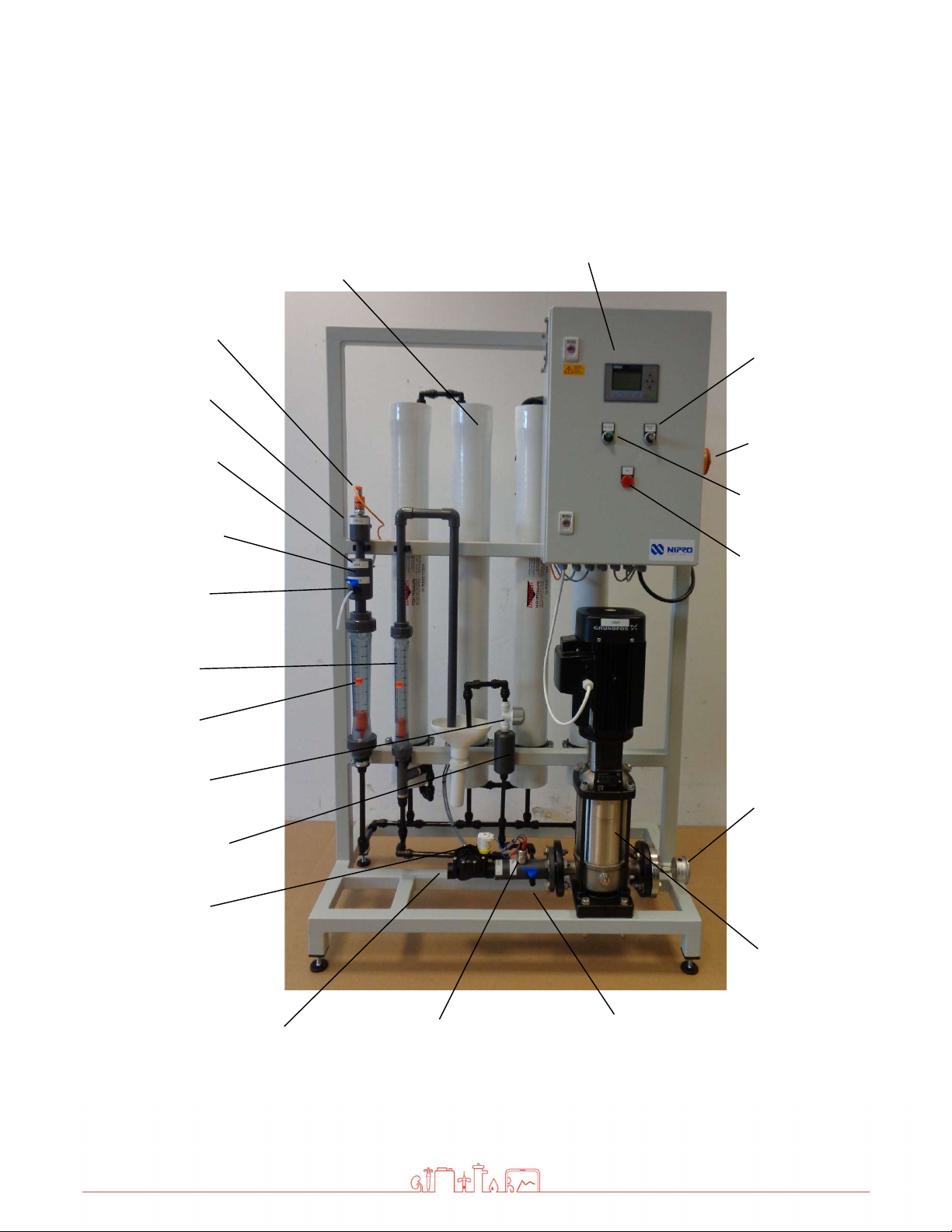
5.3 Safety devices / Components
Pressure switch
Inlet
Magnetic valve
Inlet
Pressure
pump
Manometer
Pump pressure
Main switch
Operation switch
Fault Light
Display
Disinfection
port
Flow Display
Permeat
Flow Display
Concentrate
Pressure vessel with
membrane
Permeat Flow
Connection
Raw water
connection
Emergency
Mode switch
Temperature sensor
permeate
Conductivity sensor
Permeate (backside)
Pressure sensor
Permeate (backside)
Connection backflow
permeate
Shut-off valve
Permeate
Service point
Permeate
Fehler! Verwenden Sie die Registerkarte 'Start', um Title;Title dem Text zuzuweisen, der hier angezeigt werden soll. |
12 | 04.10.2021 | Page 14
6. Installation
The installation must be conducted by the manufacturer or by personnel trained
and authorized by the manufacturer.
6.1 Environmental Condition
Conditions for the osmosis room:
Relative air moisture < 90% at 20°C
Room temperature between +10°C and +35°C (frost protected)
Equipped with floor drain, water supply and electrical supply
6.2 Assembly
Bring the device into the appropriate position
Adjust machine feet until the device stands level and secure on the floor.
Do not store easily flammable materials in the vicinity of the device.
Do not store chemicals in the vicinity of the device.
Only operate the device with the necessary water pre-treatment.
Room of osmosis may not be freely accessible. (Access for instructed personnel
only)
Fehler! Verwenden Sie die Registerkarte 'Start', um Title;Title dem Text zuzuweisen, der hier angezeigt werden soll. |
12 | 04.10.2021 | Page 15
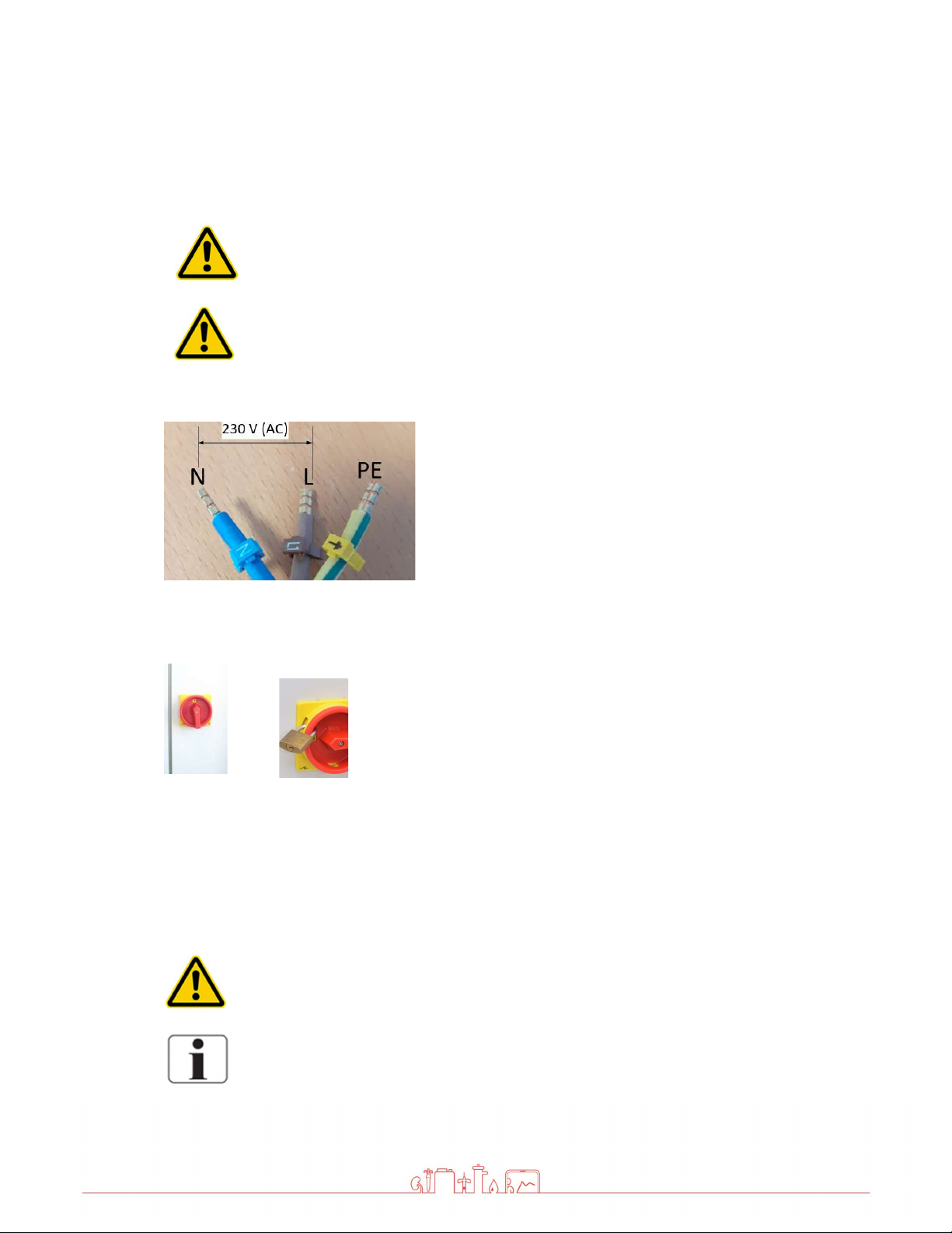
6.3 Electrical installation
The installation may only be performed by a qualified electrician.
The device must be supplied by a permanent connection, connectors are not
valid. The disconnection via the main switch at the control cabinet. The power
cord must be provided with a strain relief.
Connection cable RO Medical-Basic
For protection against a re-start of the unit, the main switch
can be locked with a padlock.
Safety class I
The device is equipped with a Protective earth terminal for prevention against
high touch current
For prevention of the hazard of an electric shock, this device may only be
connected to a power supply with protective earth.
The power cord is fixed to the device and cannot be replaced.
Fehler! Verwenden Sie die Registerkarte 'Start', um Title;Title dem Text zuzuweisen, der hier angezeigt werden soll. |
12 | 04.10.2021 | Page 16
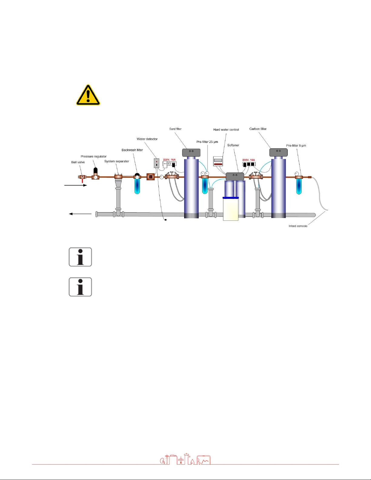
6.4 Prefiltration (Example)
Install the necessary water pre-treatment equipment first!
Only then connect the RO Medical-Basic and start up
Local water works regulations and DIN EN 1717 must be followed.
The water pre-treatment must be adapted to the local potable water quality.

Fehler! Verwenden Sie die Registerkarte 'Start', um Title;Title dem Text zuzuweisen, der hier angezeigt werden soll. |
12 | 04.10.2021 | Page 17
6.5 Commissioning
Caution, device damage!
The device must be preconnected by a suitable pre-
filter and a softening system
as well as a pressure reducer.
Permeat Flow Connection (2)
Hose nozzle d20
Raw water connection (1)
1“ Internal thread
Waste water connection
(4)
HT 40
Permeat back flow (3)
Hose nozzle d20

Fehler! Verwenden Sie die Registerkarte 'Start', um Title;Title dem Text zuzuweisen, der hier angezeigt werden soll. |
12 | 04.10.2021 | Page 18
6.6 Initial installation
1. Connect and check the raw water connection (1),
permeate flow (2), permeate back flow (3) and waste
water (4)
2. Open the inlet valve manually. To do this, turn the white
magnet coil 45° counter clockwise.
Now water is running into the device.
3. Carefully open the screw for the pump venting until a
water outlet can be seen. Then close the screw again and
reset the solenoid.
4. Make sure that the wall-mounted taps at the start and end
of the ring are open.
5.
6.
Start the device using the toggle switch.
Check all connections for leaks.
7.
8.
Open the shut-off valve permeate to the drain.
Allow the device to discard permeate for at least 30
minutes.
Fehler! Verwenden Sie die Registerkarte 'Start', um Title;Title dem Text zuzuweisen, der hier angezeigt werden soll. |
12 | 04.10.2021 | Page 19
7. Operation
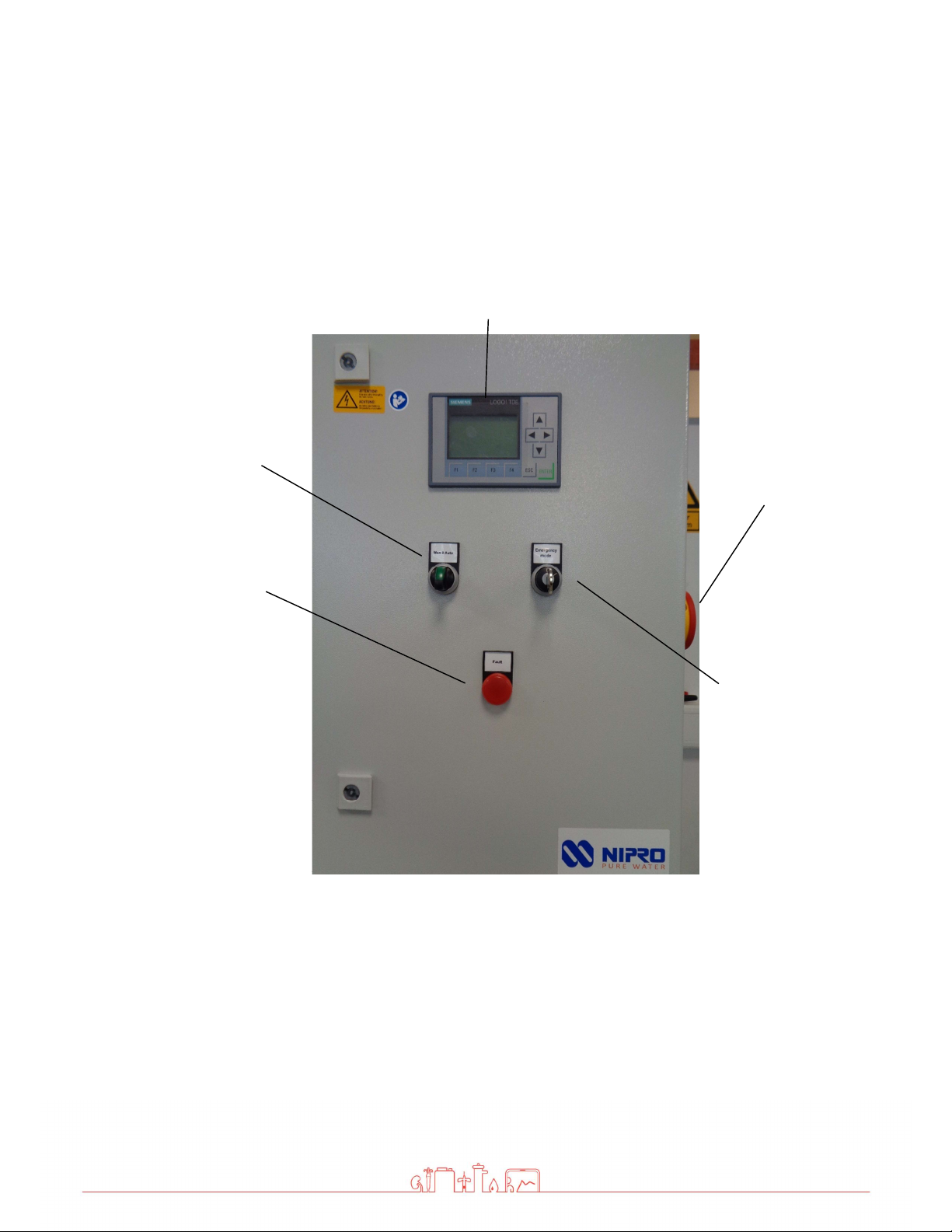
7.1 Control Panel
1. Toggle switch system on
This is used to switch the device on
and off
4th Key switch emergency operation
The device can be switched to
emergency operation here.
2. Fault light
Lights up when there is a fault
3. Display
Display of conductivity and faults
5th Main switch
With this the device can be switched off
completely
Emergency
operation switch
(4)
Right Side
Main Switch (5)
Toggle
switch (1)
Fault light (2)
Display
Fehler! Verwenden Sie die Registerkarte 'Start', um Title;Title dem Text zuzuweisen, der hier angezeigt werden soll. |
12 | 04.10.2021 | Page 20
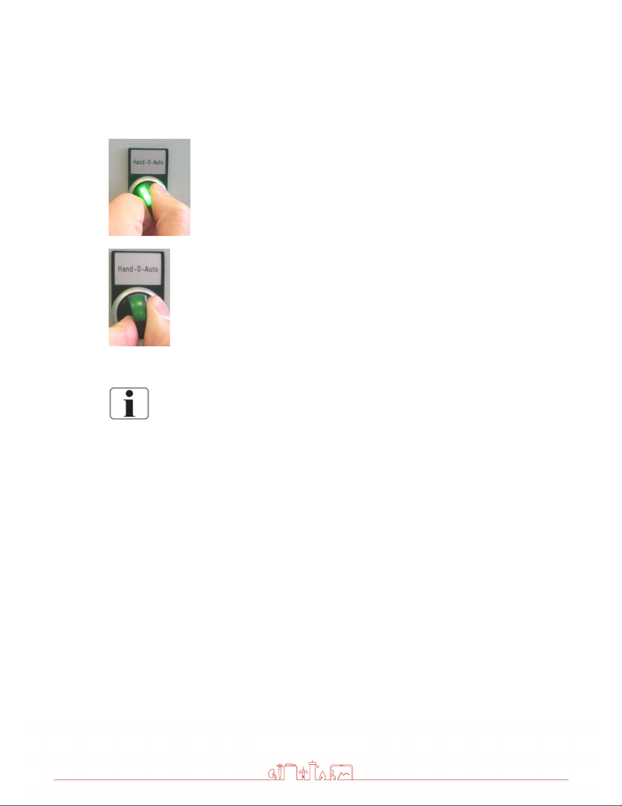
7.2 System on / off without permeate tank
System on
To start the device, turn the toggle switch to the right (on
position).
The green lamp lights up.
The pump starts after a short delay
System off
Reset toggle switch (position 0)
The green lamp goes out.
Pump stops.
If the device is switched off using the toggle switch, the rinse intervals are
carried out as programmed. If no rinsing is to take place, the device must be
switched off completely at the main switch. However, this is only
recommended for decommissioning.
Table of contents
Popular Water Dispenser manuals by other brands

vo-water
vo-water duomatik evoline installation guide

Follett
Follett chewblet 15CI100A Installation, operation and service manual

Crystal Mountain
Crystal Mountain Storm Service manual

Andrew James
Andrew James Chilled Drink Dispenser With Infuser user guide

First Sales
First Sales CITY Series Installation instructions and owner's manual

Acorn
Acorn A172108F-UBL Installation, operation and maintanance manual


