Nishigaki pump SVS-25 User manual
Popular Water Pump manuals by other brands

WilTec
WilTec 50752 Operation manual

Spartan Tool
Spartan Tool 740 Water Jet owner's manual
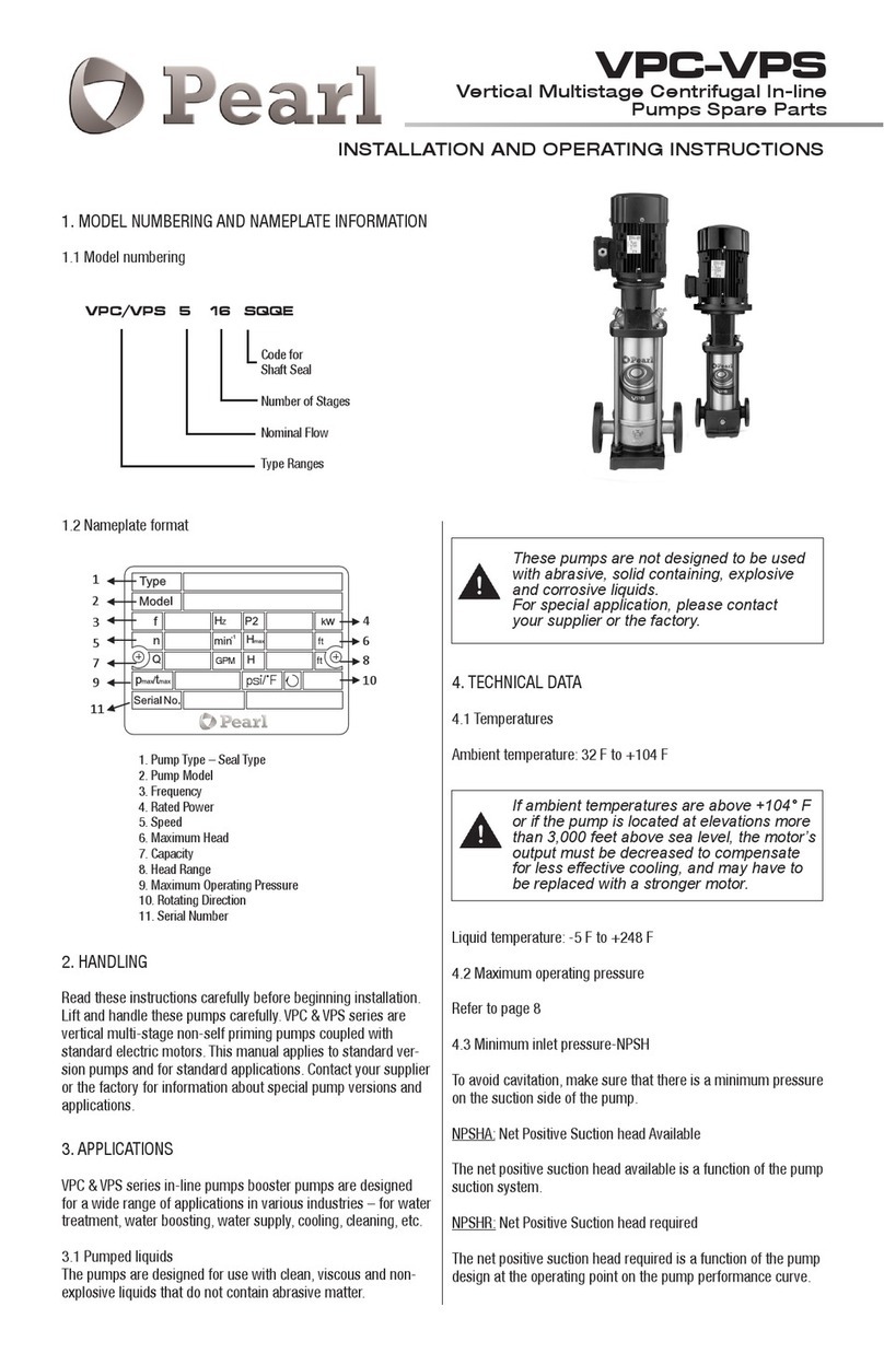
Pearl
Pearl VPS 1 Installation and operating instructions
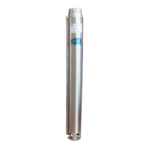
PYD Electrobombas
PYD Electrobombas ST Series Instruction manual and maintenance
Anest Iwata
Anest Iwata DDP-70B instruction manual
GORMAN-RUPP
GORMAN-RUPP 14A22-B Installation, operation, and maintenance manual with parts list
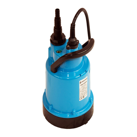
Simer
Simer OD6601G Series Use and maintenance manual

Grundfos
Grundfos SP Safety instructions and other important information

Annovi Reverberi
Annovi Reverberi AR 560 bp Twin instruction manual
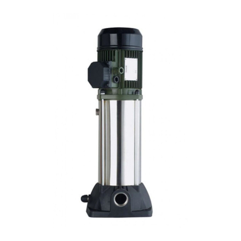
DAB
DAB KVC Series Instruction for installation and maintenance
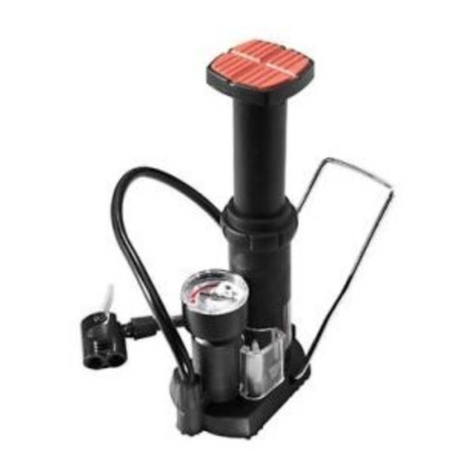
Crivit
Crivit 273306 instruction manual
BJM Pumps
BJM Pumps J400 Installation, operation & maintenance manual

Wilo
Wilo Yonos PICO 25/1-8 Installation and operating instructions

Glasswelt
Glasswelt GARLAND GEISER 391 XE instruction manual

Oase
Oase Aquarius Universal Premium Eco 4000 operating instructions

Wayne
Wayne WLS75 Operating instructions and parts manual

Becker
Becker VT 4.40 operating instructions

SPERONI
SPERONI CAM 198 operating instructions


