Nisshinbo Micro Devices NJR4652F2S1EV User manual
- 1 -
Rev.00-02S1e May 1, 2022
IM-R4652F2S1EV
- Instruction Manual -
60GHz Smart Sensor
Micro-Module
Evaluation Kit:NJR4652F2S1EV
Function:Presence Detection
Region: USA, EU
Rev.00-02S1e / May 1, 2022
© Copyright 2022
Nisshinbo Micro Devices Inc.
Microwave Business HQ
-Notice of Proprietary Information-
Documents and contents are proprietary to Nisshinbo Micro Devices Inc.
This publication and its contents may not be reproduced or distributed for any
other purpose without the written permission of Nisshinbo Micro Devices Inc.
Preliminary

60GHz Smart Sensor Micro Module (Presence Detection)
- 2 -
Rev.00-02S1e May 1, 2022
IM-R4652F2S1EV
Table of Contents
1. Description ・・・・・・・・・・・・・・・・・・・・・・・・・・・・・・・・・・・・・・・・・・・・・・・・・・・・・・・・・・・・・・・・・・・ 3
1.1 Sensors for Presence Detection ・・・・・・・・・・・・・・・・・・・・・・・・・・・・・・・・・・・・・・・・・・・・ 3
1.2 Features ・・・・・・・・・・・・・・・・・・・・・・・・・・・・・・・・・・・・・・・・・・・・・・・・・・・・・・・・・・・・・・・・・ 3
1.3 Detection Area ・・・・・・・・・・・・・・・・・・・・・・・・・・・・・・・・・・・・・・・・・・・・・・・・・・・・・・・・・・ 4
2. How to connect ・・・・・・・・・・・・・・・・・・・・・・・・・・・・・・・・・・・・・・・・・・・・・・・・・・・・・・・・・・・・・・ 4
2.1 Hardware ・・・・・・・・・・・・・・・・・・・・・・・・・・・・・・・・・・・・・・・・・・・・・・・・・・・・・・・・・・・・・・・・・ 4
2.2 Software ・・・・・・・・・・・・・・・・・・・・・・・・・・・・・・・・・・・・・・・・・・・・・・・・・・・・・・・・・・・・・・・・・ 5
3. Module configuration software setup ・・・・・・・・・・・・・・・・・・・・・・・・・・・・・・・・・・・・・・・・ 7
4. Set and get configuration ・・・・・・・・・・・・・・・・・・・・・・・・・・・・・・・・・・・・・・・・・・・・・・・・・・・・ 8
5. Presence event output ・・・・・・・・・・・・・・・・・・・・・・・・・・・・・・・・・・・・・・・・・・・・・・・・・・・・・・・ 12
6. Macro and micro threshold tuning ・・・・・・・・・・・・・・・・・・・・・・・・・・・・・・・・・・・・・・・・・・・ 13
6.1 Reading the macro and micro level ・・・・・・・・・・・・・・・・・・・・・・・・・・・・・・・・・・・・・・・・ 13
6.2 Increase Sensitivity by parameter adjustment ・・・・・・・・・・・・・・・・・・・・・・・・・・・・・・ 14
7. Signal verification mode ・・・・・・・・・・・・・・・・・・・・・・・・・・・・・・・・・・・・・・・・・・・・・・・・・・・・・・ 15
7.1 Measurement Setup ・・・・・・・・・・・・・・・・・・・・・・・・・・・・・・・・・・・・・・・・・・・・・・・・・・・・・・・・ 16
8. Firmware update ・・・・・・・・・・・・・・・・・・・・・・・・・・・・・・・・・・・・・・・・・・・・・・・・・・・・・・・・・・・・・ 17
9. Additional Documents ・・・・・・・・・・・・・・・・・・・・・・・・・・・・・・・・・・・・・・・・・・・・・・・・・・・・・・・・・・ 17
10. Revision ・・・・・・・・・・・・・・・・・・・・・・・・・・・・・・・・・・・・・・・・・・・・・・・・・・・・・・・・・・・・・・・・・・・・・・・・ 17
Caution ・・・・・・・・・・・・・・・・・・・・・・・・・・・・・・・・・・・・・・・・・・・・・・・・・・・・・・・・・・・・・・・・・・・・・・・・・・ 18

60GHz Smart Sensor Micro Module (Presence Detection)
- 3 -
Rev.00-02S1e May 1, 2022
IM-R4652F2S1EV
60GHz Smart Sensor Micro Module
Before use, please read this instruction manual carefully to ensure correct and safe use.
1. Description
This manual describes the evaluation kit of the 60GHz Smart Sensor Micro Module (hereafter
referred to as "the Sensor Module") and its presence detection software. This kit is intended
for customers interested in developing various consumer applications using the presence
detection software embedded in the sensor module.
The sensor module is mounted on an evaluation interposer board, and an evaluation USB
interface board is used on top of the interposer board.
The presence detection software included in the sensor module is capable of detecting both
large movements (macro movements) and small movements (micro movements).
The detection of presence is based on the detection of both
This paper describes the configuration of the module with presence detection software and
how to set up the software and hardware to evaluate it.
1.1 Sensors for Presence Detection
Motion sensing is a functionality that many sensors have claimed. In recent years, the sensors
are also required to detect the presence of people. Traditional motion sensors have been
designed using passive infrared (PIR) sensors, which have limited detection performance and
are not suitable for detecting fine motion. PIR sensors also require a lens. On the other hand,
60 GHz millimeter-wave sensors can detect fine motion and are typically used without the
need for a lens. Therefore, they can be used behind a plastic housing without a hole for a lens,
allowing for design-oriented product design.
The 60GHz sensor module uses advanced presence detection algorithms in the internal
controller to detect various movements with very high accuracy and to detect the presence of
humans within a specific range.
1.2 Features
- Adjustment of detection range
- Detection of subtle movement
- Detection performance is insensitive to environmental factors such as temperature, wind,
sunlight, and dust/dirt
- Provide presence detection solutions for homes, offices, and commercial buildings

60GHz Smart Sensor Micro Module (Presence Detection)
- 4 -
Rev.00-02S1e May 1, 2022
IM-R4652F2S1EV
1.3Detection Area
・Field of View (FOV):Azimuth±45°/Elevation±45°
2. How to connect
2.1 Hardware
The evaluation kit (model name: NJR4652F2S1EV) consists of the following components
①USB interface board for evaluation (NJR4652K)
②Interposer board for evaluation (NJR4652F2S1K) on which NJR4652F2S1 is mounted
③USB Cable
Figure 1 Configuration of Evaluation Kit
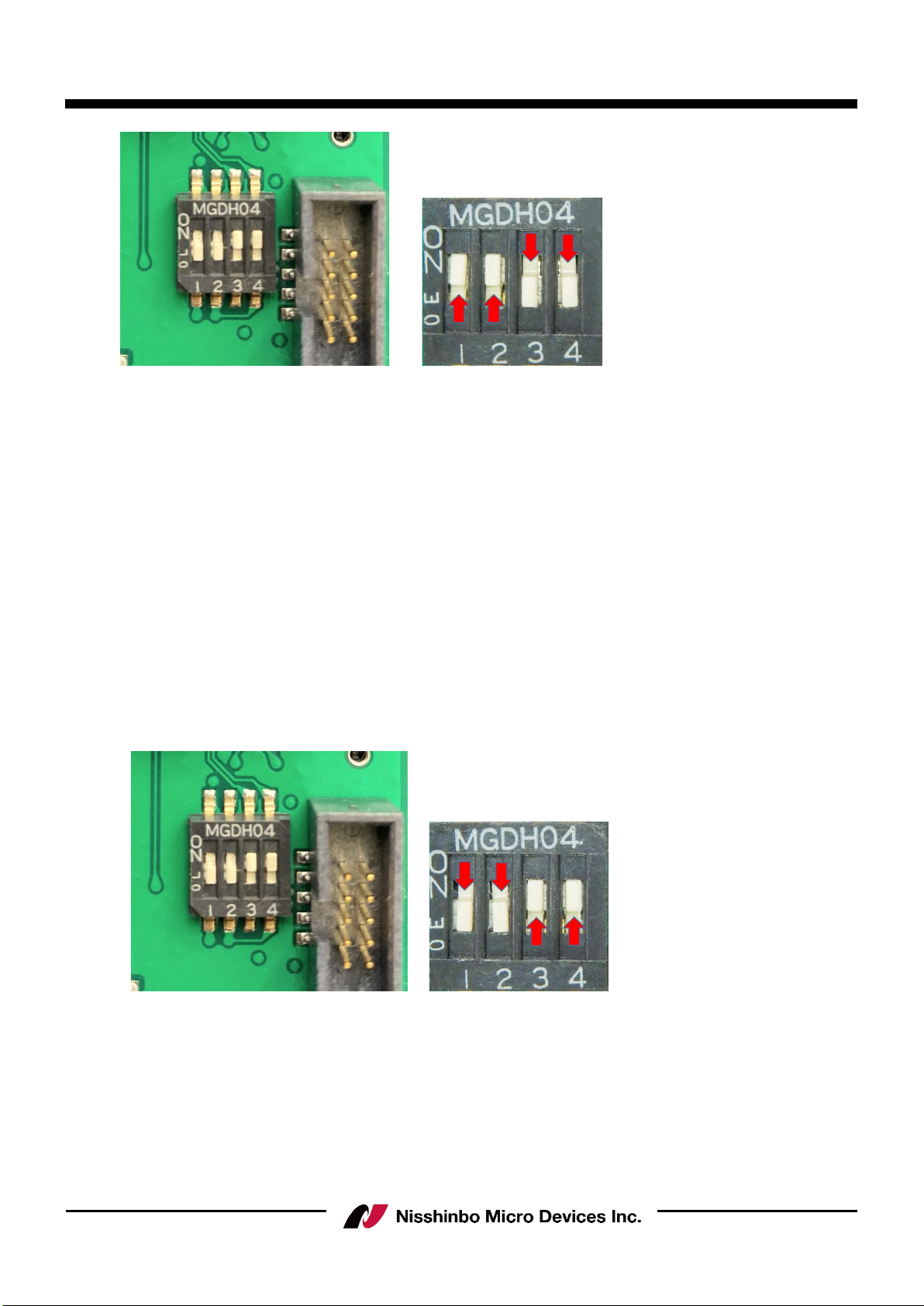
The module can be connected with UART serial interface (baud rate 115200, 8N1) for
command communication.
There is a converter chip on the motherboard to convert the UART interface to USB for PC
connection. Set the dip switch as follow to enable USB_UART connection.
③USB Cable
60GHz Sensor Module
②Interposer board for Evaluation
↑
Elevation±45°
↓
←Azimuth±45°→
①USB Interface board for Evaluation
60GHz Smart Sensor Micro Module (Presence Detection)
- 5 -
Rev.00-02S1e May 1, 2022
IM-R4652F2S1EV
Figure 2 USB_UART selection
User needs to download and install the driver at following link to ensure the USB to UART
converter chip can work at PC.
https://www.infineon.com/cms/en/search.html#!term=CypressDriverInstaller_1&view=all
1. Connect to the URL.
2. Press the file of “DOWNLOAD-CypressDriverinstaller_1.exe”
3. The page of Html starts downloading, after download open the page of html.
4. After connect to the switched page, the driver starts downloading.
In addition to the UART serial interface, the sensor module has a USB terminal.
Setting the DIP switch as follows will directly connect the USB terminal of the sensor module
to the USB connector.
In either setting, the PC will recognize it as a VCOM port.
Figure 3 USB_MCU selection

60GHz Smart Sensor Micro Module (Presence Detection)
- 6 -
Rev.00-02S1e May 1, 2022
IM-R4652F2S1EV
2.2 Software
The "Infineon-BGT60TR13C_Config_Tool-Software-v02_00-EN.zip" is the GUI software release
package for this evaluation kit. (The version is updated irregularly.)
Please use the GUI software after downloading it from the Infineon website below.
https://www.infineon.com/cms/en/applications/solutions/sensor-solutions/presence-detection/
This archive contains the following files after extraction to the folder
‘’Infineon_BGT60TR13C_Embedd_Presence_ConfigTool’’:
・IFX_BGT60TR13C_Embedd_MCU4_Module_Config_v1.5.0_build-c196d75.exe
(The version at the time of this instruction manual is v1.5.0)
GUI software rises up, after PC connects to Evaluation Kit and proceeding the ‘’exe’’ file.
60GHz Smart Sensor Micro Module (Presence Detection)
- 7 -
Rev.00-02S1e May 1, 2022
IM-R4652F2S1EV
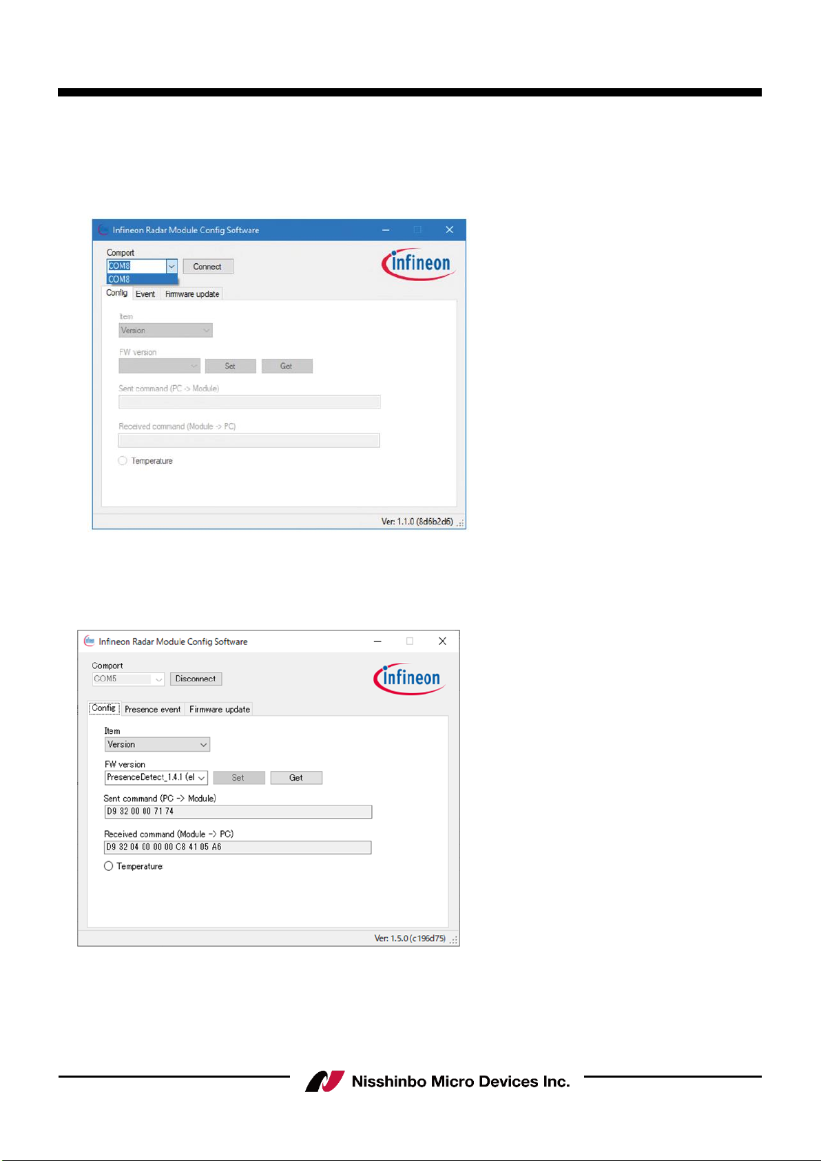
3. Module configuration software setup
Connect the radar board to the PC through USB, and open the file
“IFX_BGT60TR13C_Embedd_MCU4_Module_Config.exe”. Select the correct comport number
(COM8 in this example) and press “Connect”.
Figure 4 Comport selection
If the board is connected successfully, a firmware version will show in the box. Otherwise a fail
message will be shown at the bottom.
Figure 5 Firmware version get success

60GHz Smart Sensor Micro Module (Presence Detection)
- 8 -
Rev.00-02S1e May 1, 2022
IM-R4652F2S1EV
4. Set and get configuration
The user can set or get the configuration of the radar under the “Parameter” tab. The following
items are currently available:
Item
Description
Version
Get the firmware version in MCU.
Max. range
[0.66 to 10.2]
Get or set the maximum detection distance for presence detection.
The setting would stored in Flash; default is 1.00 m.
The any value, up to 10.2, is available on typing.
Sensitivity
Get or set the sensitivity level presence detection; higher sensitivity
means more sensitivity to small movements. Changing the sensitivity
would change the macro and micro threshold values. The setting
would be stored in Flash; default is medium.
Note: The user is recommended to use a high-sensitivity setting for
optimal performance at angles and for use cases such as a person
sitting on a chair behind a table.
Event control
Enable/disable active output command of presence or absence event
change. The setting would be stored in Flash; default is on.
Get presence event
Get current presence detection result.
Presence detect on/off
Set presence detection to on or off. Default is on. When set to off,
radar chip power would also be set to off.
RFCW mode
Enable or disable the RF continuous wave mode for FCC test.
Presence detection needs to be off before enabling this mode.
Disable: Disable RFCW mode.
Low: Set RFCW output at 61.02 GHz.
Mid: Set RFCW output at 61.25 GHz.
High: Set RFCW output at 61.48 GHz.
Low TX off: Set RFCW test at 61.02 GHz with TX off.
Mid TX off: Set RFCW test at 61.25 GHz with TX off.
High TX off: Set RFCW test at 61.48 GHz with TX off.
Self-test
Perform tests related to the radar chip. Presence detection needs to
be off before enabling this mode. Self test cover SPI interface
checking and RF test utilizing internal test hardware. Please ensure to
run the self test in an environment that there is an empty space of
50cm in front of the radar.
Temperature
Get temperature on the radar chip (°C).
Sleep mode
Set the radar module to deep sleep mode. The module will wake up
again when data is received at the UART RX pin. A preamble byte
such as 0x00 is needed to add in the next command so the command
is correctly received at the module (to compensate for wake-up delay
time).

60GHz Smart Sensor Micro Module (Presence Detection)
- 9 -
Rev.00-02S1e May 1, 2022
IM-R4652F2S1EV
Calibration mode
Enable/disable active output command of calibration message. A
calibration message would output periodically when enabled. The
message would contain the activity level used to compare with the
macro/micro threshold value at that time.
Calibration rate
[1 to 4]
Set the update rate of the calibration message output. Selection is 1
to 4. For example, setting the value to 4 would change the output
message rate to 4 Hz.
Detect mode
Set presence detection detect mode. The setting would be stored in
Flash; default is macro then micro.
Macro then micro: The radar would first detect macro motion for
presence, and enter micro motion detect mode when the object
movement is smaller.
Macro only: Radar would only detect macro movement.
Micro only: Radar would only detect micro movement.
Macro and micro: Radar would always detect both macro and micro
movement; either kind of motion exceeding the threshold would be
treated as a presence.
Signal verify mode
Enable/disable active output command of range bin profile. A range
bin profile would output periodically (1sec) when enabled. The range
bin profile is an array of floating numbers showing the received signal
level (in dB) at different distance. This feature can be used to
measure the RF attenuation due to plastic casing.
Min. range
[0.00 to 9.77]
Get or set the minimum detection distance for presence detection.
The user needs to ensure this value is smaller than the max. range.
The setting would be stored in Flash; default is 0.00 m.
The any value, up to 9.77, is available on typing.
Macro threshold
[more than 0.0]
Threshold value used in macro movement detection. After changing
this value, the sensitivity would be customized. The setting would be
stored in Flash; default is 1.00.
Micro threshold
[more than 0.0]
Threshold value used in micro movement detection. After changing
this value, the sensitivity would be customized. The setting would be
stored in Flash; default is 25.00.
Macro valid
[0.5 to 30.0]
Time-out value (s) used to judge motion is no longer macro
movement. For example, if the value is 1, it means a detected value
below the macro threshold for 1 s continuous would be treated as no
macro movement. The setting would be stored in Flash; default is 1.
Micro valid
[1.5 to 30.0]
Time-out value (s) used to judge the motion is no longer micro
movement. The judging criteria are the same as for a valid macro
value. The setting would be stored in Flash; default is 4.

60GHz Smart Sensor Micro Module (Presence Detection)
- 10 -
Rev.00-02S1e May 1, 2022
IM-R4652F2S1EV
Macro trigger range
[1 to 64]
Get or set the macro trigger range for macro movement detection.
When setting a higher value, the user needs to enter the inner
detection zone to trigger a presence. The value is a multiple of 0.33
m. The setting would be stored in Flash; default is 1.
Macro trigger delay
[0 to 255]
Get or set the trigger delay for macro movement detection. Input
value is multiple of 0.25 s. For example, by setting the value to 3,
the radar will determine the motion as macro movement for a
continuous 0.75 s of major motion. The setting would be stored in
Flash; default is 0.
Chirp per frame
[1 to 16]
Get or set the number of chirp per frame for coherent integration.
Setting a higher value, radar will send out more chirps in a frame and
use for coherent integration. Resulting in a better signal to noise
ratio. Notice that power consumption will increase for setting higher
value, as the RF active time will also increase. The setting would be
stored in Flash; default is 1.
Unique ID
Get the unique ID of the module.
Reset config.
Reset all setting stored in Flash to default.
Figure 6 Configuration item list

60GHz Smart Sensor Micro Module (Presence Detection)
- 11 -
Rev.00-02S1e May 1, 2022
IM-R4652F2S1EV
After pressing the “Set” or “Get” button, the relevant binary command would be shown in the
command text box. The developer can use that command for reference or checking. The
temperature button enables periodic, every 0.5ms, polling of the radar chip temperature.
Figure 7 Configuration set or get example

60GHz Smart Sensor Micro Module (Presence Detection)
- 12 -
Rev.00-02S1e May 1, 2022
IM-R4652F2S1EV
5. Presence event output
When event control is turned on, the presence detection result would be shown under the
“Event” tab.
Items
Description
Presence event
Presence event Presence detection result.
In: Moving object detected in the zone.
Out: No moving object detected in the zone.
Distance (m)
Detected distance range of the closest moving object, in meters.
Time (s)
Relative event time, in seconds. The time starts from power on, it is
not an absolute time.
The received event command would be shown in the command text box for reference. When
calibration mode is enabled, a calibrate message box would also be shown.
Figure 8 Presence detect event page
60GHz Smart Sensor Micro Module (Presence Detection)
- 13 -
Rev.00-02S1e May 1, 2022
IM-R4652F2S1EV
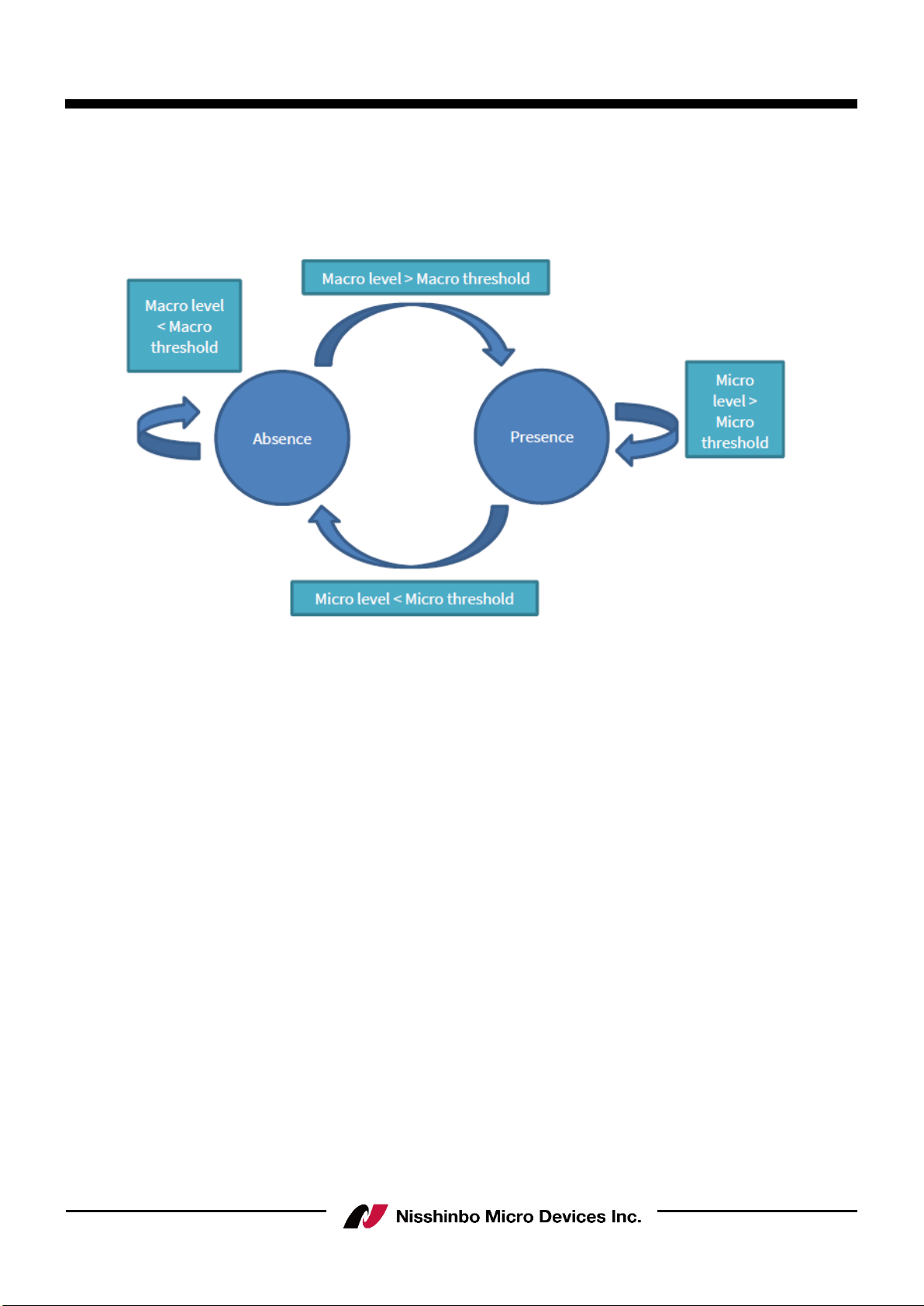
6. Macro and micro threshold tuning
In presence detection solution, there is a macro and micro mode concept. The macro then
micro detection mode could be illustrated using a state machine.
Figure 9 Presence detect state diagram
Assume the detection is initially in absence state, it will check the macro level. When macro
level is above macro threshold, state will transit from absence to presence. It stays in presence
state as far as the micro level is above micro threshold. When micro level is below micro
threshold, state will transit from presence to absence.
Sensitivity setting (High, Medium and Low) have pre-defined macro and micro threshold value.
If user find the sensitivity is not enough even with high sensitivity, they can manually set the
micro and macro threshold value to fit their use case.
6.1 Reading the macro and micro level
Following steps are used to enable macro and micro level tuning.
1. Turn “Calibration mode” to “On”.
2. Set “Detection mode” to “macro and micro”
3. Set “Calibration rate” to 4, so the solution will report the update rate as fast as possible.
After these settings, the presence detection solution would report the macro and micro level
readings. Example as below (macro level 1.155, micro level 219.1).
macro 1.155223 at 0.33, micro 219.102509 at 0.33

60GHz Smart Sensor Micro Module (Presence Detection)
- 14 -
Rev.00-02S1e May 1, 2022
IM-R4652F2S1EV
6.2 Increase Sensitivity by parameter adjustment
In order to increase the sensitivity further, user needs to:
(A) Find out the noise floor value of the system
(B) Set the threshold above the noise floor
To find out the noise floor value, user needs to empty the detection area so no one is inside.
Put the radar module into a product casing so it will have a temperature that’s similar to
product environment, as temperature could affect the noise floor. Record the macro and micro
level for a period of time and take the maximum reading as macro and micro noise level.
Threshold level can then be set to 15%-20% above noise level.
60GHz Smart Sensor Micro Module (Presence Detection)
- 15 -
Rev.00-02S1e May 1, 2022
IM-R4652F2S1EV
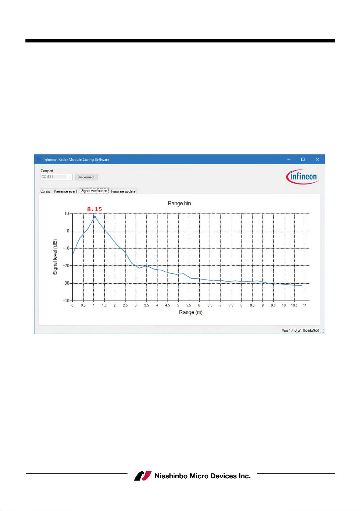
7. Signal verification mode
The radar FF module provide a feature called signal verification mode to check the RF
attenuation due to the plastic material. Signal verification mode is a feature to output range bin
profile. Basic theory about how FMCW radar measure distance can refer to following link.
The range bin profile is an array of floating numbers showing the received signal level (in dB) at
different distance. Example of a range bin profile is shown below. This feature can be used to
measure the RF attenuation due to plastic casing.
Figure 10 Range bin profile

60GHz Smart Sensor Micro Module (Presence Detection)
- 16 -
Rev.00-02S1e May 1, 2022
IM-R4652F2S1EV
7.1 Measurement Setup
Put the radar in an open area, to minimize the reflected signal due to other static objects. At
1m distance, put a corner reflector to maximize the reflected signal at 1m. User can then look
at the signal level at 1m to compare the difference between with and without plastic casing. If
the difference is smaller than 2dB, it can be considered as a good plastic casing without
attenuating the RF signal too much.
Figure 11 Measurement setup
Recommended corner reflector size is as follow(a:50mm, L:70mm)
Figure 12 Corner reflector

60GHz Smart Sensor Micro Module (Presence Detection)
- 17 -
Rev.00-02S1e May 1, 2022
IM-R4652F2S1EV
8. Firmware update
Nisshinbo Micro Devices Inc. is an Ecosystem partner of Infineon Technologies, Inc. and uses
the firmware written in the sensor module (Product Name: NJR4652JS1) under license from the
company. In addition, the Firmware update in the GUI menu does not function with this
evaluation kit.
9. Additional Documents
Specific user guides are available, including the following:
Will be updated as necessary.
10. Revision
Version
Release Date
Remarks
00.02
May. 1, 2022
Preliminary 2

60GHz Smart Sensor Micro Module (Presence Detection)
- 18 -
Rev.00-02S1e May 1, 2022
IM-R4652F2S1EV
Caution
Notes on the evaluation kit
1) This evaluation kit is designed assuming that it is used only for technical evaluation, operation
confirmation and development by customers. Please do not use for purposes other than those for technical
evaluation and development. This does not conform to the design quality for the finished product.
2) This evaluation kit is for electronic engineers, not consumer products. Consider appropriate use and safety
at the customer. Nisshinbo Micro Devices Inc. (NISD) are not responsible for any damage or fire caused
by using this product. Even in normal use, please discontinue use if there is abnormality.
3) The detail of this evaluation kit including specifications and this instruction manual may be subject to
change without notice.
4) This evaluation kit may not comply with the radio law prescribed by the country you use. Please use in
an environment where radio waves do not leak to the outside.
5) When handling this product, be sure to take measures to prevent static electricity.
6) NISD shall not be responsible for any bodily injury, fires or accidents, property damage or any
consequential damages resulting from the misuse or misapplication of its products.
Notes on this document
7) NISD will refuse to reprint part or all of this material and instruction manual without our permission
without permission or use it for other purpose such as duplication.
8) Application circuits, programs, usage methods, etc., which are described in this material and instruction
manual are only reference information, and for the occurrence of intellectual property rights and other
rights of third parties caused by these and other damages , NISD does not make any guarantees. In
addition, this material does not grant license of third party or our intellectual property rights and other
rights.
Table of contents
Other Nisshinbo Micro Devices Motherboard manuals


