Nissindo WS-315 User manual
MANUAL
Congratulation &
Thank You for
Purchasing
Nissindo
Products!
OPERATING INSTRUCTIONS
PROFESSIONAL KARAOKE SPEAKER
Thank you for purchasing this unit. To
make full and effective use of this unit,
please read this Owner's Manual
carefully before operating it. Please
retain this manual for future reference.
w w w . N i s s i n d o U S A . c o m
Full Range Passive/Non-Powered
WS-315 15-inch WOOFER
Full Range Active/Powered
WS-315A 15-inch WOOFER

2
CONTENTS
INTRODUCTION............................................................................................................................................... 3
SYSTEM FEATURES........................................................................................................................................... 3
SAFETY INSTRUCTIONS............................................................................................................................. 4~5
SPEAKER CONNECTION METHODS AND INFORMATION....................................................................6
SYSTEM APPLICATIONS.................................................................................................................................. 7
• WS-315 2-Way Full Range Passive/Non-powered Speaker System Functioning...........................7
• WS-315A 2-Way Full Range Active/Powered Speaker System Functioning.....................................8
• Connecting the Speaker for Model WS-315 & WS-315A................................................................... 10
CONTROLS AND FUNCTIONS......................................................................................................................11
• Rear Panel Features................................................................................................................................................11
SYSTEM SETUP GUIDELINES........................................................................................................................ 12
• Installation Setup....................................................................................................................................................12
1. Mounting the Speaker to the Wall................................................................................................. 12
2. Placing the Speaker on the Floor to Monitor Singing.............................................................. 13
3. Placing the Speaker on the Portable Stand................................................................................. 13
4. Placing the Speaker on the Speaker Mounting Pole................................................................ 13
5. Store the Speaker Inside a Portable Case................................................................................... 13
PHYSICAL DIMENSIONS....................................................................................................................... 14
SPECIFICATIONS............................................................................................................................................ 14
FINAL WORDS TO USER.............................................................................................................................. 14
TROUBLESHOOTING.............................................................................................................................. 15
WARRANTY..................................................................................................................................................... 16
AGENCY REGULATORY NOTICES.............................................................................................................. 17
CONTACT INFORMATION........................................................................................................................... 18
Safety
Applications
Set Up
Speaker
Features
Intro
Troubleshooting
Warranty
Final Words
Notices
Spec
Dimensions
Contact Us
Connection

3
Features
SYSTEM FEATURES
WS-315 (2-WAY FULL RANGE PRO SPEAKER)
• 1 x 15” high power transducer with 50mm voice coil
• 1 x 1.75” diaphragm compression driver
• 2-Way full range system
• High SPL and high sensitivity speaker
• 90° x 60° controlled coverage pattern
• 1 x input speakon connector
• 1 x output speakon connector
• Heavy duty protective grill
• Grip handles for easy portability
WS-315A (2-WAY FULL RANGE PRO
SPEAKER)
• 1 x 15” high power transducer with 50mm voice coil
• 1 x 1.75” diaphragm compression driver
• 2-Way full range system
• High SPL and high sensitivity speaker
• 90° x 60° controlled coverage pattern
• LCD screen
• MP3 music control
• USB, SD, Bluetooth, and FM radio capability
• 2 x Microphone inputs
• 3 x Speaker outputs
• Heavy duty protective grill
• LED lights on the inner rim of the grill
• Grip handles for easy portability
Intro
INTRODUCTION
The remarkable quality in our all purpose speakers has only
gotten better through time. We only use the newest,
technologically improved resistors and capacitors materials
for the crossovers of our speakers, allowing that crystal clear
audio that our Nissindo speakers are known for. Every year
we search for new ideas and inspirations for the future
speakers of Nissindo, to carry on the top audio quality that
all speakers are meant to have. And today, we would like to
present not one but two new speakers that are joining the
WS Series speakers. Adding to our Wide Range Speaker
“WS” Series professional speakers is the new WS-315
passive and WS-315A active speaker.
Equipped with an amplifier that can power itself and an
additional speaker, the WS-315A is the perfect choice for
party speaker, and it only gets better with the additional
functions it has. Treble and bass adjustments allow the user
to shake the ground with hard hitting bass and enhance the
tone of the music instruments. Not only is it a powered
speaker, the WS-315A also features many input capability:
RCA, USB, SD, Bluetooth, and FM radio. So either you have
a USB filled with music, SD card from your phone, connect
wirelessly using Bluetooth, or simply listen to the radio, all is
possible with the Nissindo WS-315A.
BASS
LF
HIGH
HF
HIGH
HF
MID
MF
MID
MF
THIS SPEAKER INCLUDES THE FOLLOW:
• Speaker: One piece
• Instructional Manual: 1 pc
• Power Cable: 1 pc (only for WS-315A)
• Warranty & Registration Card: 1 pc
WS-315 WS-315A
4
Safety
SAFETY INSTRUCTIONS
We will not notify you any errors or changes in this manual in
advance. If there are any errors and changes in this manual,
we will make the corrections in a timely manner. The
corrections and changes will be on our website. Therefore,
please visit our website at NissindoUSA.com frequently to find
out the most updated information, corrections on errors and
changes in this manual. You may also contact us at toll free at
1-800-318-2218.
CAUTIONS FOR INSTALLATION
POWER SUPPLY / POWER CORD
• Only use the voltage specified as correct for the device.
The required voltage is printed on the name plate of the
device.
• Use only the included power cord.
• Do not place the power cord near heat sources such as
heaters or radiators, and do not excessively bend or
otherwise damage the cord, place heavy objects on it, or
place it in a position where anyone could walk on, trip
over, or roll anything over it.
• Remove the electric plug from the outlet when the device is
not to be used for extended periods of time, or during
electrical storms.
• When removing the electric plug from the device or an
outlet, always hold the plug itself and not the cord. Pulling
by the cord can damage it.
DO NOT OPEN
• Do not open the device or attempt to disassemble the
internal parts or modify them in any way. The device
contains no user-serviceable parts. If it should appear to
be malfunctioning, discontinue use immediately and have
it inspected by qualified Nissindo service personnel.
WATER WARNING
• Do not expose the device to rain, use it near water or in
damp or wet conditions, or place containers on it
containing liquids which might spill into an openings.
• Never insert or remove an electric plug with wet hands.
RISK OF ELECTRIC SHOCK
DO NOT OPEN
CAUTION: TO REDUCE THE RISK OF ELECTRIC SHOCK DO NOT
REMOVE COVER (OR BACK) NO USER-SERVICEABLE PARTS
INSIDE REFER SERVICING TO QUALIFIED PERSONNEL
ABNORMALITY
• If the power cord or plug becomes frayed or damaged,
or if there is a sudden loss of sound during use of the
device, or if any unusual smells or smoke should appear to
be caused by it, immediately turn off the power switch,
disconnect the electric plug from the outlet, and have the
device inspected by qualified Nissindo service
personnel.
• If this device should be dropped or damaged, immediately
turn off the power switch, disconnect the electric plug from
the outlet, and have the device inspected by qualified
Nissindo service personnel.
LOCATION
• Always consult qualified Nissindo service personnel if the
device installation requires construction work, and make
sure to observe the following precautions.
• Choose mounting hardware and an installation location
that can support the weight of the device.
• Avoid locations that are exposed to constant vibration.
• Inspect the device periodically.
• When transporting or moving the device, always use two
or more person. Attempting to lift the device by yourself
may damage your back, result in other injury, or cause
damage to the device itself.
• Before moving the device, remove all connected cables.
• Do not use the device in a confined, poorly-ventilated
location. If this device is to be used in a small space
other than an EIA-standard rack, make sure that there is
adequate space between the device and surrounding
walls or other devices: at least 30cm at the sides, 30cm
NO GOOD

polarity coding. The side of the wire with a ridge or other
coding is usually considered positive polarity.
If desired, consult Nissindo technical support for
speaker wire and connection options.
The speakers have coded terminals that accept a variety or
wire connectors.
To ensure proper polarity, connect each + terminal on the
back of the amplifier or receiver to the respective + (red)
terminal on each speaker. Connect the – (black) terminals in
a similar way. See the owner’s guides that were included
with your amplifier, receiver and television to confirm connec-
tion procedures.
IMPORTANT: Do not reverse polarities (i.e., + to – or – to +)
when making connections. Doing so will cause poor imaging
and diminished bass response.
ADJUSTING
Check the speakers for playback, first by setting the system
volume control to a minimum level, and then by applying
power to your audio system. Play a favorite music or video
segment and increase the system volume control to a comfort-
able level.
You should hear balanced audio reproduction across
the entire frequency spectrum. If not, check all wiring connec-
tions or consult the authorized dealer from whom you
purchased the system for more help.
The amount of bass you hear and the stereo-image quality
will be affected by a number of different factors, including the
room’s size and shape, the construction materials used to
build the room, the listener’s position relative to the speakers,
and the position of the speakers in the room.
Listen to a variety of music selections and note the bass level.
If there is too much bass, move the speakers away from
nearby walls. Conversely, if you place the speakers closer to
the walls, there will be more bass output.
CARING
Each enclosure has a finish that does not require any routine
maintenance. When needed, use a soft cloth to remove any
fingerprints or dust from the enclosure or grille.
5
NOTE
NOTE
behind and 30cm above. Inadequate ventilation can
result in overheating, possibly causing damage to the
device(s), or even fire.
• Do not use the speaker’s handles for suspended installation.
Doing so can result in damage or injury.
• Do no expose the device to excessive dust or vibrations,
or extreme cold or heat (such as in direct sunlight, near a
heater, or in a car during the day) to prevent the possibility
of panel disfiguration or damage to the internal
components.
• Do not place the device in an unstable position where it
might accidentally fall over.
CONNECTIONS
• Before connecting the device to other devices, turn off the
power for all devices. Before turning the power on or off
for all devices, set all volume levels to minimum.
CAUTION
• When turning on the AC power in your audio system,
always turn on the device LAST, to avoid speaker damage.
When turning the power off, the device should be turned
off FIRST for the same reason.
• Do not insert your fingers or hands in any gaps or
openings on the device (ports, etc.).
• Avoid inserting or dropping foreign objects (paper, plastic,
metal, etc.) into any gaps or openings on the device
(ports, etc.). If this happens, turn off the power immediately
and unplug the power cord from the AC outlet. Then
have the device inspected by qualified Better Music
Builder service personnel.
• Do not use the device for a long period of time at a high
or uncomfortable volume level, since this can cause
permanent hearing loss. If you experience any hearing
loss or ringing in the ears, consult a physician.
• Do not operate the device if the sound is distorting.
Prolonged use in this condition could cause overheating
and result in fire.
• Do not rest your weight on the device or place heavy
objects on it, and avoid using excessive force on the
buttons, switches or connectors.
GETTING STARTED
WIRING
IMPORTANT: Make sure all equipments are turned off before
making any connections.
For speaker connections, use a high-quality speaker wire with

6
OUTPUT INPUT
2+
1+
2–1–
TO
AMPLIFIER
Connector Panel
OUTPUT INPUT
2+
1+
2–1–
TO
AMPLIFIER
FULL
RANGE
BI-AMP
LF
HF
Connector Panel on Multi-Way Systems
OUTPUT INPUT
PASSIVE BI-AMPLING
INPUT PASSIVE OUTPUT
2+ 2+
2– 2–
1+ 1+
1– 1–
SUB
WOOFER
INPUT BI-AMPLING OUTPUT
2+ 2+
2– 2–
1+ 1+
1– 1–
SUB
WOOFER
Connector Panel on Subwoofers
EXAMPLE OF SPEAKON CONNECTOR
There are two groups on the speakon connectors: Group 1
(+1, –1) and Group 2 (+2, –2) as indicated in the diagram. In
order to use it, your speaker must have multi-functions (i.e.
enable two sources of signal for input). If your speaker does
not have multi-functions, it would not work with the Group 2
for connection. Please refer to the following diagram for
connection.
Applications
SYSTEM APPLICATIONS
Speakon Outputs
The upper Speakon jack has both Channel 1 and
Channel 2 outputs, so it is especially useful for parallel,
bi-amp, or BRIDGE mono operation. The other Speakon
carries only Channel 2's output. See the illustrations at
above.
SPEAKON Y CONNECTORS
INPUT OUTPUT
L
O
C
K
L
O
C
K
TO CHANNEL 2
SPEAKER
TO CHANNEL 1
SPEAKER
2–
1–
1+ 2+
REFERENCE CONNECT
8
4
2
+
–
8
4
2
–
+
SPEAKON CONNECTORS
INPUT OUTPUT
L
O
C
K
L
O
C
K
SOURCE
(from active/powered)
BRIDGE
2–
1–
1+ 2+
REFERENCE CONNECT
8
4
2
+
–
Source (INPUT) comes from the output source of the
active/powered speaker while the bridge (OUTPUT)
connects to the passive/non-powered speaker.
A speakon cable is required to connect the “OUTPUT”
of the acive/powered speaker to the “INPUT” of the
passive/non--powered speaker. Please order the speakon
cable from our authorized dealers.
NOTE

PORTABLE SYSTEM
ON
POWE R
OFF PR OF ES SIO NA L PO WER A MP LIF IE R MA -1 20 0 G2
PROTE CT
PEAK
SIGNA L
–0
–
8
–2–24
–4–20
–6–18
–8–16
–10–14 –12
CH 1
–0
–
8
–2–24
–4–20
–6–18
–8–16
–10–14 –12
CH 2
ON
POWE R
OFF PR OF ES SIO NA L PO WER A MP LIF IE R MA -20 00
PROTE CT
PEAK
SIGNA L
–0
–
8
–2–24
–4–20
–6–18
–8–16
–10–14 –12
CH 1
–0
–
8
–2–24
–4–20
–6–18
–8–16
–10–14 –12
CH 2
TM
POWER
RF
AF
CHAN.
5 10 15 20 25 30 35 40
-30 -25 -20 -15 -10 -5 0 PEAK
CH 002 MUTE
RF
AF
CHAN.
5 10 15 20 25 30 35 40
-30 -25 -20 -15 -10 -5 0 PEAK
CH 004 MUTE
SET SET
ANTENNA-BVOLUME
DUAL CHANNEL RECEIVER
RECEIVER - A LCDANTENNA-A VOLUME RECEIVER - B LCD
64 SELECTABLE WIRELESS S YSTEM
UHF
7
WS-315
2-WAY FULL RANGE PASSIVE/NON-POWERED SPEAKER SYSTEM FUNCTIONING
Recommended System Setup:
We recommend using two amplifiers to connect to two
separate speakers (i.e. one amplifier connects to a Hi and
Mid frequency speaker and the other amplifier connects to
the other Low Bass speaker) in order to control the different
sound frequency on the speakers. It has an advantage over
PASSIVE/NON-POWERED SPEAKERS
WS-315
FROM POWER AMPLIFIER MA-1200 G2
CONNECT TO SPEAKON INPUT
LARGE FORMAT SPEAKER
WS-8215 (High Grade)
LARGE FORMAT SPEAKER
WS-8215 (High Grade)
PASSIVE/NON-POWERED SPEAKERS
WS-315
FROM POWER AMPLIFIER MA-1200 G2
CONNECT TO SPEAKON INPUT
POWER AMPLIFIER
MA-2000
POWER AMPLIFIER
MA-1200 G2
Wall Wall
NISSINDOUSA.COM
ENGINEERED in U.S.A.
Manufacture in P.R.C.
386140905350
15” WOOFER / FULL RANGE
< Passive / Non-Powered >
POWER RMS: 200W
FREQUENCY: 40Hz ~ 18kHz
IMPEDANCE: 8 ohms
WS-315
OUTPUTINPU T
a parallel connection where only one amplifier is used to
connect to two separate speakers (i.e. one Hi and Mid
frequency speaker and one Low Bass speaker) in
connection to produce mono sound only.
8
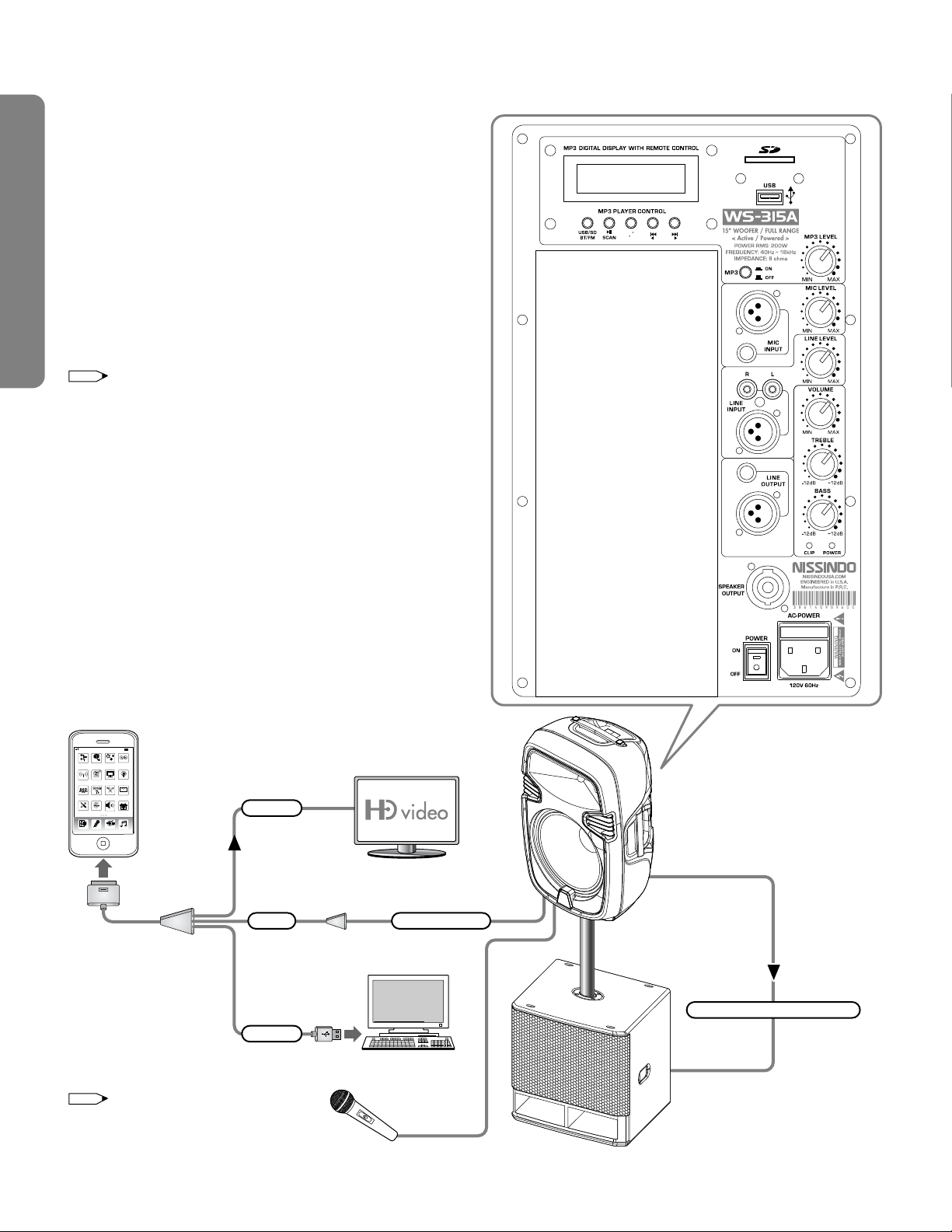
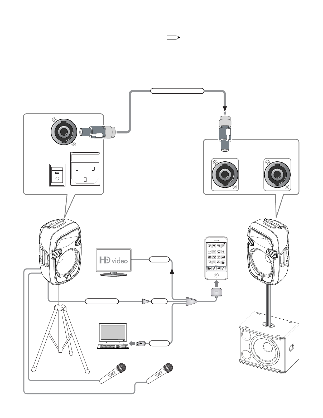
2-WAY FULL RANGE ACTIVE/POWERED SPEAKER SYSTEM FUNCTIONING
The diagram indicates that signals from the sources (i.e. mixer,
iPod or MP3) to the active/powered speaker through the
powered subwoofer, which acts as a bridge for bringing
signal, are limited in output from the active/powered speaker.
To increase the output from the active/powered speaker, you
need to use a passive/non-powered speaker (instead of an
active/powered speaker) and add a power amplifier to drive
the system. In this case, both the powered subwoofer and the
passive/non-powered speaker are controlled separately by a
mixer and a power amplifier respectively. Therefore, the bass
and the full range sound are totally separate.
NOTE
The equipment shown in the
above diagram such as TV, iPhone,
wired microphone and PC are not
included.
ACTIVE/POWERED
SPEAKER: WS-315A
PC
iPhone / iPod
VIDEO
CHARGER
AUDIO INPUT to AUX
This cable is from Apple
part # MB129LL
AT&T 9:42AM 88%
Entertainmen t Auto Priority
Wireless HD Vi deo
Connection S et up
Speaker
Music
Customer Care
Mail
Vocal
Project Wireless
LyriPS on TV
Free Resources
Stat
Pro Sound
Group sing KTV
Technical Suppor t
S A I S
BASS POWERED SUBWOOFER
OUTPUT TO SUBWOOFER INPUT
WIRED MIC.
NOTE
When using the active/powered speaker for full range
coverage, the output is limited. If the output is not high enough, you
need to add a non-powered speaker and also a power amplifier to
the system.
WS-315A
WS-315A REAR PANEL
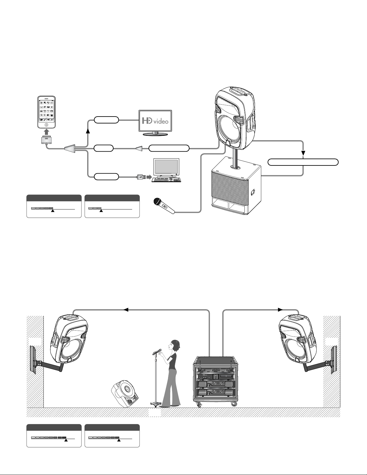
9
POWER
0W 1000W
Average
300W
SOUND COVERAGE
0FT 100FT
Average
50FT
SOUND COVERAGE
0FT 100FT
Average
80FT
POWER
0W 1000W
Average
700W
Floor
Wall Wall
PERFORMER
PORTABLE
SYSTEM
PASSIVE/NON-POWERED PASSIVE/NON-POWERED
ACTIVE/POWERED
MONITOR
PC
AT&T 9:42AM 88%
Entertainment Auto Pri ority
Wireless HD Video
Connection Setup
Speaker
Music
Customer Care
Mail
Vocal
Project Wireless
LyriPS on TV
FreeRe sources
Stat
ProSo und
Group sing KTV
Technical Support
S A I S
iPhone / iPod
VIDEO
AUDIO INPUT to AUX
CHARGER
ACTIVE/POWERED
SPEAKER: WS-315A
WIRED MIC.
OUTPUT TO SUBWOOFER INPUT
HIGH PORTABILITY
This speaker is designed for high portability. It is very easy to
carry. You may also use the flight cases to carry audio
equipment to go anywhere with these speakers for rental or
recreational purposes.
When using the active/powered speaker for full range
coverage, the output is limited. If the output is not high
enough, you need to add a non-powered speaker and also
a power amplifier to the system.
HIGH POWER
This speaker series have two types of speakers:
active/powered speaker and passive/non-powered speaker.
When using the active/powered speaker alone, the output
power is limited to 200 watts. For more than 200 watts in
output, two passive/non-powered speakers and a
high-power amplifier are required to generate higher power
as high as 1,000 watts.
ON
POWER
OFF PROFE SSION AL POWE R AMPLIF IER MA- 1200 G2
PROTECT
PEAK
SIGNAL
–0
–
8
–2–24
–4–20
–6–18
–8–16
–10–14 –12
CH1
–0
–
8
–2–24
–4–20
–6–18
–8–16
–10–14 –12
CH2
ON
POWER
OFF PROFE SSION AL POWE R AMPLIF IER MA- 2000
PROTECT
PEAK
SIGNAL
–0
–
8
–2–24
–4–20
–6–18
–8–16
–10–14 –12
CH1
–0
–
8
–2–24
–4–20
–6–18
–8–16
–10–14 –12
CH2
TM
POWER
RF
AF
CHAN.
5 10 15 20 25 30 35 40
-30 -25 -20 -15 -10 -5 0 PEAK
CH 002 MUTE
RF
AF
CHAN.
5 10 15 20 25 30 35 40
-30 -25 -20 -15 -10 -5 0 PEAK
CH 004 MUTE
SET SET
ANTENNA-BVOLUME
DUALCHANNEL RECEIVER
RECEIVER- A LCDANTENNA-A VOLUME RECEIVER- B LCD
64SELECTABLE WIRELESS SYSTEM
UHF
If you want more bass, you
need to add a power
subwoofer of various sizes (i.e.
12-inch, 15-inch, 18-inch and
20-inch power subwoofer).
10
Please order the speakon cable for the active/powered
speaker (WS-315A) inside the package and the
passive/non-powered speakers (WS-315) from our
authorized dealers. The speakon cables are available in 20
feet, 30 feet and 50 feet.
NOTE
You can hook up the active/powered speaker with the
passive/non-powered speakers, so a power amplifier is not
needed for connection. Two input sources such as MP3 (including
iPhone/iPod) and dynamic microphone can be added to the
active/powered speaker.
CONNECTING THE SPEAKER FOR MODEL WS-315 & WS-315A
SPEAKON NL4FC CONNECT
ACTIVE/POWERED
WS-315A
PC
AT&T 9:42AM 88%
Entertainment Auto Priority
Wireless HD Video
Connection Set up
Speaker
Music
Customer Care
Mail
Vocal
Project Wireless
LyriPS onTV
Free Resources
Stat
Pro Sound
Group sing KTV
TechnicalSupport
S A I S
iPhone / iPod
VIDEO
CHARGER
AUDIOINPUT to AUX
WIRED MIC. 2 WIRED MIC. 1
This cable is from Apple
part # MB129LL
PASSIVE/NON-POWERED
WS-315
BASS POWERED SUBWOOFER
DFS-112 SUB / DFS-115 SUB
(DYNAMIC FUSION SERIES)
OUTPUTINPUT
SPEAKER
OUTPUT
POWER
AC - POWER
120V 60Hz
ON
OFF
11
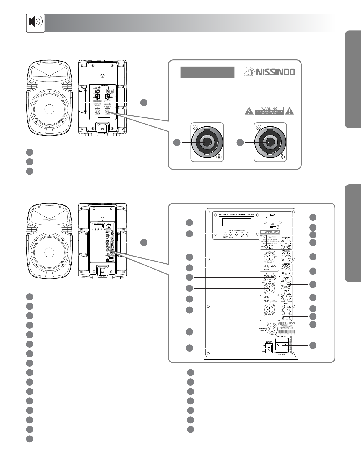
WS-315WS-315A
Rear View
Rear View
Front View
Front View
Speaker
CONTROLS AND FUNCTIONS
SPEAKER HANDLE
SPEAKER INPUT TERMINAL (Speakon)
SPEAKER OUTPUT TERMINAL (Speakon)
WS-315 REAR PANEL:
WS-315A REAR PANEL:
SPEAKER HANDLE
LCD DISPLAY
CONTROL FUNCTIONS
XLR MICROPHONE INPUT
6.35mm MICROPHONE OUTPUT
RCA PHONO (R3+L) LINE INPUTS
XLR LINE INPUT
6.35mm LINE OUTPUT
XLR LINE OUTPUT
SPEAKER OUTPUT
POWER ON/OFF SWITCH
SD CARD READER SLOT
USB SLOT
MP3 ON/OFF
USB/MP3 LEVEL CONTROL
MICROPHONE INPUT LEVEL CONTROL
LINE INPUT LEVEL CONTROL
VOLUME CONTROL
TREBLE CONTROL
BASS CONTROL
CLIP INDICATOR
POWER LED INDICATOR
CONNECT THIS TO 120V 60Hz AC WITH THE
SUPPLIED POWER CORD
4
5
6
7
8
9
10
11
12
13
14
15
17
18
19
20
21
22
23
16
1
1
NISSINDOUSA.COM
ENGINEERED in U.S.A.
Manufacture in P.R.C.
386140905350
15” WOOFER / FULL RANGE
< Passive / Non-Powered >
POWER RMS: 200W
FREQUENCY: 40Hz ~ 18kHz
IMPEDANCE: 8 ohms
WS-315
OUTPUTINPUT
32
2
3
8
5
6
4
9
7
10
11
12
13
15
14
16
17
18
19
20
23
21
22
1
2
3
1
2
3

12
SYSTEM SETUP GUIDELINES: INSTALLATION SETUP
Set Up
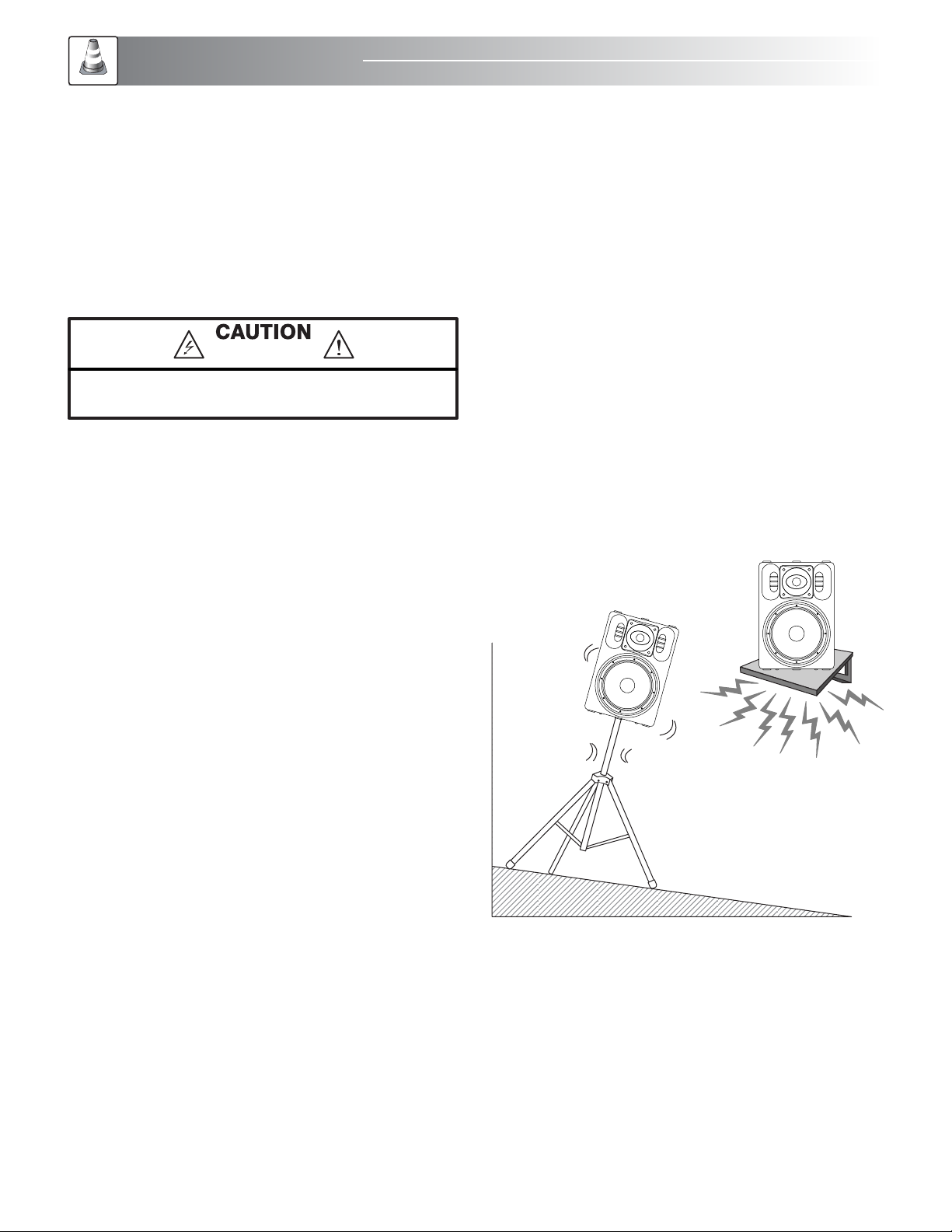
PANEL WALL 2”X4” WOOD STUD
We recommend that the speakers be tiled at an angle, so
that it aims at audience’s ear level in order to achieve the best
accoustic quality.
NOTE
180° (ADJUSTABLE)
LEFT RIGHT
20 Feet
-6 dB
80 Degree
-6 dB
Wall
1
2
NOTE
1. MOUNTING THE SPEAKER TO THE WALL
STEP : Place the wall mount panel on the wall and put
three or more screws to fasten it.
STEP : Then, put the speaker firmly onto the mount.
Adjust the speaker up and down for rotation at different
angles to achieve the maximum sound effect.
The structure of the wall must be strong enough to hold up to
100 pounds.
How to Adjust the Wall Mount (SL-001)
Adjust the wall mount left/right at 180 degree and up/down
at 90 degree for rotation at different angles to achieve the
best sound effect. Once you have set up the right position,
then you can use the screw to tighten it up. Part Number:
SL-001 (Optional) for wall mount.
Mounting to Solid Wood or Wood Studs
In North America, most of the houses have 2”x4” wood studs
inside the panel walls. You may use stud finder to locate the
wood studs. Then, you can drive the screw into the wood
stud to mount the speaker bracket and hold it firmly.
12.5 inch
31.8 cm
9.8 inch
25 cm 3.2 inch
8 cm
11.2 inch
28.3 cm
1.4 inch / 3.5 cm5.5 inch / 14 cm
Dimensions: Wall Mount (SL-001)
Wall
UP
DOWN
90°
(ADJUSTABLE)

13
Floor
WS-315 & WS-315A
SUBWOOFER
SPEAKER
MOUNTING
POLE
(Adjustable)
38 inch
96.5 cm
The speaker mounting pole as indicated in the diagram is
not included with any of our speaker models. You may order it
directly from our authorized dealers near you.
NOTE
LEFT SPEAKER
(Stand is not included)
RIGHT SPEAKER
(Stand is not included) PORTABLE CASE
2. PLACING THE SPEAKER ON THE FLOOR TO
MONITOR SINGING
This speaker can be placed on the floor to perform the vocal
monitoring function for live singing experience. It can also be
used for business conference, coffee shop and church, etc.
4. PLACING THE SPEAKERS ON THE SPEAKER
MOUNTING POLE (Adjustable)
Part Number: AM91 (Optional)
5. STORE THE SPEAKER INSIDE A PORTABLE
CASE
A speaker can be placed and stored inside a portable case
as indicated in the diagram below, which would make
traveling easy.
3. PLACING THE SPEAKERS ON THE PORTABLE
STAND
The speakers can be mounted onto the optional portable
stand (see figure below). Make sure that the mounting system
(hardware, stand, etc.) is capable of supporting four times the
weight (approximately 25 lbs per speaker) of the speakers.
Part Number: AMS001B (Optional).
14
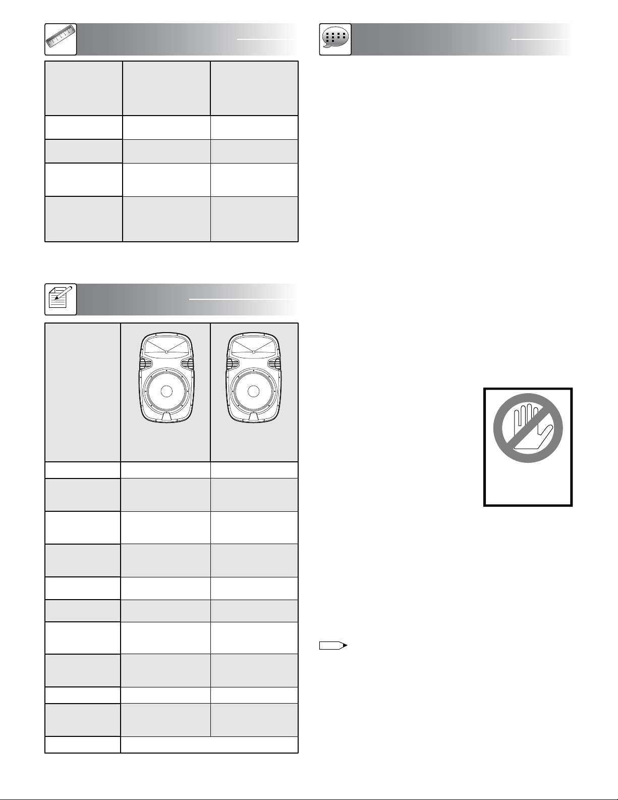
PHYSICAL DIMENSIONS
Dimensions
WS-315A
ACTIVE
POWERED SPEAKER
MODEL
NET WEIGHT
WS-315
PASSIVE
NON-POWER SPEAKER
15.7×26.8×14.6 in
40×68×37 cm
19.9×30.3×17.3 in
50.5×77×44 cm
(each)
33.1 lb / 15 Kg
(each)
37.5 lb / 17 Kg
(each)
15.7×26.8×14.6 in
40×68×37 cm
19.9×30.3×17.3 in
50.5×77×44 cm
(each)
43 lb / 19.5 Kg
(each)
47.4 lb / 21.5 Kg
(each)
SHIPPING WEIGHT
DIMENSIONS
(WxHxD)
PACKING
DIMENSIONS
(WxHxD)
“SPOT” RANGE
FREQUENCY
RESPONSE
HIGHLIGHTED
FEATURES
SENSITIVITY
SPECIFICATIONS
Spec
POWER
RMS
SUPPORTED
FIXTURE
WOOFER
(Low Frequency)
CABINET TYPE
TYPE
MODEL
TWEETER
(High Frequency)
Compression Driver
1.75” Diaphragm
40Hz ~ 18kHz
98 dB
Lightweight for
ultimate portability
200 Watts
Construction Plastic
15” (1 unit)
Ceiling Mount,
Wall Mount,
Floor Stand
2-Way Full Range
Front
WS-315A
ACTIVE
POWERED SPEAKER
Compression Driver
1.75” Diaphragm
40Hz ~ 18kHz
98 dB
Lightweight for
ultimate portability
Front
200 Watts
Construction Plastic
15” (1 unit)
Ceiling Mount,
Wall Mount,
Floor Stand
2-Way Full Range
WS-315
PASSIVE
NON-POWER SPEAKER
IMPEDANCE 8 ohm8 ohm
FINAL WORDS TO USER
The engineering team of Nissindo has many years of
experience in audio equipment design. The team constantly
develops new audio technologies, designs innovative audio
and Karaoke equipment to suit your specific needs and
provides you great ideas for home entertainment.
Our engineering team also designs audio equipment for
commercial use by restaurants, coffee shops, churches, and
school auditoriums, etc. If the commercial area for audio
equipment installation exceeds 2,000 square feet, we highly
recommend you to hire audio professionals to handle the
installation in order to avoid risks in breaking the equipment
with improper installation and safety protection purposes.
We also provide educational and technical information on
audio equipment and technologies. For example, we provide
free installation diagrams to make it easier to connect the
system. In addition, to get best connections for the sharpest
image and sound quality, we provide hot tip for choosing
the high quality type of A/V cable connections. Free
information on audio equipment and technologies available
for download from our website,
ww w.NissindoUSA.com.
Please do not remove the “Yellow
Label” in the rear of the machine;
otherwise, the warranty will be void
automatically. We design it to protect
your own safety. If repair and
maintenance service is needed,
please contact us directly or hire a
professional technician. To learn more
about the technical aspects, visit our
website www.NissindoUSA.com and download the
relevant information for review.
Before hooking up the system, turn off the AC powers on all
machines including audio/video equipment and TV.
Otherwise, it may damage the equipment, especially on the
HDTV in which a spot might appeared on the TV screen.
After hooking up the system, double check the audio/video
connections to ensure that they are connected correctly.
Sometimes, loose or poor cable quality would affect
the microphone effects, picture quality, or even cause the
machine to shut down suddenly.
Again, we must thank you for choosing Nissindo product.
We hope you can make the best use of the machine and
enjoy it for years to come. If you have any questions
regarding our product, please feel free to contact us at
ww w.NissindoUSA.com.
Any form of
tampering with this
product will void
the warranty.
NOTE
Final Words

15
Troubleshooting
TROUBLESHOOTING
1. SYMPTOM: NO SOUNDS COMING OUT FROM THE
SPEAKERS
Probable causes:
1. The A/C power of the speaker is turned off.
2. Wrong A/C power selection (i.e. 110V~ 220V).
Remedy:
A. Turn on the A/C power of the speaker.
B. Make sure the receiver or amplifier is on and the source is
playing.
C. Check all wires and connections between receivers,
amplifiers and speakers. Make sure all wires are connected,
none of the speaker wires are frayed, cut or punctured, and
that no wires are touching each other.
D. Review proper operation of your receiver or amplifier.
E. Choose the right A/C power.
2. SYMPTOM: NO SOUNDS COMING OUT FROM ONLY
ONE SPEAKER
Probable cause:
The A/C power of the speaker is turned off.
Remedy:
A. Check the "Balance" control on your receiver or amplifier.
B. Check all wires and connections between receiver,
amplifier and speaker. Make sure all wires are connected,
none of the speaker wires are frayed, cut or punctured, and
that no wires are touching each other.
C. In Dolby®Digital or DTS®mode, make sure that the
receiver or processor is configured so that the speaker in
question is enabled.
D. Turn off all electronics and switch the speaker in question
with another speaker that is working correctly. Turn
everything back on, and determine whether the problem is in
the same place: i.e., the speaker that was working previously
now has no sound and the speaker that was not working
now sounds fine. If the problem is in the same place, the
source of the problem is most likely with your receiver or
amplifier, and you should consult the owner's manual for
further information. If the problem is with the speaker, consult
your dealer for further assistance, or visit our web site for
technical support.
3. SYMPTOM: NOISES FROM THE SPEAKER.
Probable cause:
The A/C power cord of the speaker is not grounded.
Remedy:
Change a new magnet cord of the A/C power cord.
4. SYMPTOM: MICROPHONE VOLUME IS TOO LOW.
Probable causes:
A. The microphone is poorly connected to the speaker.
B. The volume on the speaker is too low.
Remedy:
A. Check the connection between the microphone and the
speaker. Make sure that they are connected properly.
Condense microphone doesn't work with the speaker. You
may need to change to a dynamic vocal microphone.
B. Turn the volume to an appropriate level. If the volume is
still not high enough, you may need to upgrade your existing
audio system to a system with much higher output.
5. SYMPTOM: CRACKING NOISES FROM THE SPEAKER.
Probable cause:
The tweeter may be burned out.
Remedy:
Replace with a new tweeter.
Note: we recommend hiring a professional to change a
tweeter in order to do it properly.
6. SYMPTOM: SOUNDS LIKE DAZZ, DAZZ, DAZZ ........
COMING FROM THE SPEAKER.
Probable cause:
The cable (with small gauges) is over 100 feet.
Remedy:
Change to a higher quality cable preferably 12 and 14
gauges.
7. SYMPTOM: TOO MUCH MICROPHONE FEEDBACK
FROM THE SPEAKER.
Probable cause:
Incorrect tremble and bass adjustments on the speaker.
Remedy:
Adjust the tremble and bass to an appropriate level to avoid
microphone feedback.

16
WARRANTY
ONE-YEAR LIMITED WARRANTY FOR HOME USE
EQUIPMENT
Our one-year warranty covers both parts and labors. The
warranty becomes effective from the date of your purchase for
one year.
Our warranty only covers defects due to product
defectiveness with free of defects in materials or workmanship.
However, our warranty does not cover defects due to normal
wears, damage in transit, improper use, abuse or failure to
follow the proper instructions for maintenance. This warranty is
void in the event of unauthorized repairs, alternations,
modifications and removing of the product label.
Please also note that our warranty does not cover any
shipping cost for the return of defective products to us for
inspection, repair and maintenance. Our warranty for
Nissindo products can only be executed in North America.
90-DAY LIMITED WARRANTY FOR PUBLIC AND
COMMERCIAL USE EQUIPMENT
Our 90-day warranty applies to speakers, amplifiers, mixers
and microphones for both public and commercial use such as
restaurant, coffee shop, KTV nightclub, church and school, etc.
It covers both parts and labors. The warranty becomes
effective from the date of your purchase for 90 days.
Our warranty only covers defects due to product
defectiveness with free of defects in materials or workmanship.
However, our warranty does not cover defects due to normal
wears, damage in transit, improper use, abuse or failure to
follow the proper instructions for maintenance. This warranty is
void in the event of unauthorized repairs, alternations,
modifications and removing of the product label.
Please also note that our warranty does not cover any
shipping cost for the return of defective products to us for
inspection, repair and maintenance. Our warranty for
Nissindo products can only be executed in North America.
Warranty
ADDITIONAL NOTES:
1. Limited warranty for home use equipment is only valid in
North America.
2. Limited warranty is valid only if you purchase our products
from our authorized dealers (including both regular retailers
and online retailers) in North America. If you choose to
purchase our products from an authorized dealer, we will not
provide any limited product warranty for you. To protect your
limited product warranty, please purchase our products from
one of our authorized dealers in North America near you.
3. Limited warranty is automatically void if the yellow label
stating “No Warranty After Opening” is removed from the
product.
TO REGISTER YOUR WARRANTY
Please fill out the warranty card that came with your unit,
download or submit online warranty form. However, we
need the invoice for your purchase in order to process this
warranty. You may also register your warranty online.
Please visit our website at www.NissindoUSA.com.
17
AGENCY REGULATORY NOTICES
Federal Communications Commission Notice
These limits are designed to provide reasonable protection
against harmful interference in a residential installation. This
equipment generates, uses, and can radiate radio frequency
energy and, if not installed and used in accordance with the
instructions, may cause harmful interference to radio
communications. However, there is no guarantee that
interference will not occur in a particular installation. If this
equipment does cause harmful interference to radio or
television reception, which can be determined by turning the
equipment off and on, the user is encouraged to try to correct
the interference by one or more of the following measures:
• Reorient or relocate the receiving antenna.
• Increase the separation between the equipment and the
receiver.
• Connect the equipment into an outlet on a circuit different
from that to which the receiver is connected.
• Consult the dealer or an experienced radio or television
technician for help.
Modifications
The FCC requires the user to be notified that any changes or
modifications made to this device that are not approved may
void the user’s authority to operate the equipment.
Cables
Connections to this device must be made with shielded cables
with metallic RFI/EMI connector hoods to maintain
compliance with FCC rules and regulations.
Materials Disposal
Disposal of this material can be regulated because of
environmental considerations. For disposal or recycling
information, contact your local authorities or the Electronic
Industries Alliance (EIA) (http://www.eiae.org).
Disposal Of Waste Equipment By Users In
Private Households In The European Union
This symbol on the product or on its packaging indicates that
this product must not be disposed of with your other
household waste. Instead, it is your responsibility to dispose of
your waste equipment by handing it over to a designated
collection point for the recycling of waste electrical and
electronic equipment. The separate collection and recycling of
your waste equipment at the time of disposal will help to
conserve natural resources and ensure that it is recycled in a
manner that protects human health and the environment. For
more information about where you can drop off your waste
equipment for recycling, please contact your local city office,
your household waste disposal service or the shop where you
purchased the product.
Japanese Notice
Japanese Power Cord Notice
Japanese Material Content Declaration
A Japanese regulatory requirement, defined by Specification
JIS-C-0950, 2005, mandates that manufacturers provide
Material Content Declarations for certain categories of
electronic products offered for sale after July 1, 2006.
Korean Notice
Recycling Program
The terms and availability of these programs vary by
geography because of differences in regulatory requirements
and local customer demand.
因为在当地的监管要求和客户的需求,这些条件和程序的情
况不同。
Notices

18
CONTACT INFORMATION
MAILING ADDRESS
NISSINDO
29300 Kohoutek Way #150
Union City, CA 94587
U.S.A.
TELEPHONE NUMBERS
USA Region
USA Toll Free: 1-800-318-2218
Sales & Marketing: 510-477-9955
Customer Service: 510 -477-9955
FAX NUMBERS
USA Region
Sales & Marketing: 510-477-9922
Customer Service: 510 -477-9922
WORLD WIDE WEB
E-mail: sales@nissindousa.com
Website: w w w.NissindoUSA.com
MAINTENANCE
With proper maintenance and regular service, it would maintain the machine quality and prolong its life. We
recommend you to print the following information clearly for future reference on maintenance and warranty.
MODEL#____________________________ DATE PURCHASED (MM/DD/YYYY)_____________________________
DEALER NAME_____________________________ CITY_____________ ST./PROV._______ ZIP/P.C.____________
DEALER WEBSITE http://www.______________________________________________ INVOICE #_____________
DEALER PHONE #_____________________________ DEALER E-MAIL______________________________________
Contact Us

19
MAINTENANCE
NOTE

Thank you for purchasing this unit. To
make full and effective use of this unit,
please read this Owner's Manual carefully
before operating it. Please retain this
manual for future reference.
Printed on 100% Recycled Paper Code: 20140820 Design and Engineered in U.S.A. Comments E-mail to sales@nissindousa.com Copyright © 2014 NISSINDO U.S.A. All rights reserved. Legal trademark.
386140931500
This manual suits for next models
1
Table of contents


