Sonodyne SM 100Ak User manual

SM100Ak
2 way nearfield active monitor owners manual
www.sonodyne.com
S
N
O
D
N
Y
E
O
S
N
O
D
N
Y
E
O
S
N
O
D
N
Y
E
O
SM 100Ak
Introduction •Safety •Unpacking •Fig 1 & 2
INTRODUCTION
Congratulations on your purchase of the SM 100Ak near field active studio monitor. The SM 100Ak has all the makings of a truthful
reference device. The high grade transducers, the aluminium die cast rigid enclosure, the active amplification, the on board EQ, among
others, result in sound that is neutral and transparent. You may thus depend on the SM 100Ak to accurately meet your professional
monitoring needs.
SAFETY
•Please ensure proper earthing.
•Please keep away from moisture.
•The equipment is capable of producing SPL in excess of 100 dB. Long term exposure may cause permanent hearing damage.
•Ensure that the speakers are not covered while in use. Restricted airflow at the rear of the unit will cause it to heat up.
UNPACKING
While removing the units from the carton, please do not hold the speaker’s front. The high frequency transducer is located near the top of
the cabinet, on the front baffle; you may accidentally damage the transducer.
The best way to safely unpack the monitors is to open the top of the carton, keep the EP filler piece on, turn the entire box upside down
and pull off the carton box. Then remove the filler pieces, the protective cloth and moulded baffle cover.
Page 1
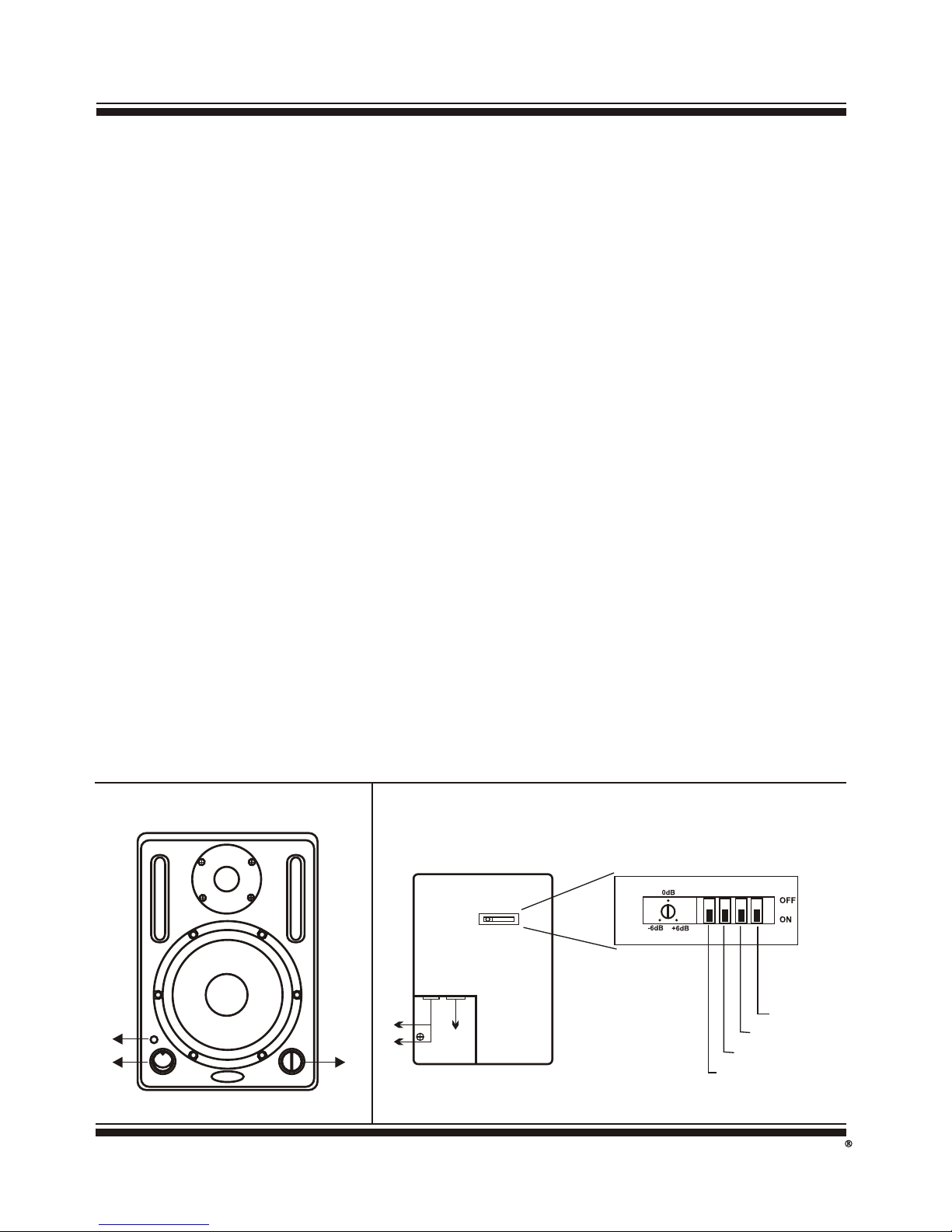
FIG. 2: REAR PANELFIG. 1: FRONT PANEL
S
N
O
D
N
Y
E
O
1
2
3
GAIN 1 32 4
1
23
1. TRS Input
2. XLR input
3. 3 pin IEC mains inlet
Treble Tilt -2 dB
Bass Tilt -4 dB
Bass Tilt -2 dB
Bass Roll-Off

Controls and Features
Page 2
S
N
O
D
N
Y
E
O
SM 100Ak
FRONT PANEL (refer to Fig. 1 on page 1)
1. Power Switch: This switch is used to turn power ON/OFF
2. Power Indicator: This lights up when power is ON
3. Master Level Control: This control increases or decreases the overall level. Full master level corresponds to 0 dB.
REAR PANEL (refer to Fig. 2 on page 1)
•GAIN: The SM 100Ak has a variable gain control. The gain is factory set to 0 dB. With the level control on the front panel set to
maximum position (fully clockwise) and an input signal of -6 dBu, the SM 100Ak will typically produce an output of 109 dB SPL
at 1 meter in an anechoic environment.
The variable gain setting allows the user to get a good sensitivity match when using either professional or semi-professional
equipment. Using the gain control, the monitor can be set for inputs of -6 dBu to +6 dBu.
•LF SWITCH (BASS ROLL-OFF): Switch 1 when ON introduces a low frequency roll-off into the response curve. The effect of the
roll-off (6 dB per octave @ 100 Hz) is shown in Fig. 6 on page 6.
For many applications, removal of deep bass content allows you to raise the overall output level, permitting LOUD mixing. But,
keep in mind that removing deep bass content from monitors may actually result in an inaccurate bass reproduction.
•ROOM COMPENSATION (LF) (BASS TILTS): Switches 2 & 3 when ON activates a filter @ 80 Hz, to reduce the low frequency
output by 2 dB & 4 dB respectively. Engaging both switches produces a 6 dB roll-off. These functions can be used to compensate
for the build-up of low frequencies that occur when the speakers are placed near walls or corners, or on the workbench surfaces.
When the monitors are at a free standing position, away from walls and workbenches turn these switches OFF. The changes in
low frequency response using switches 2 & 3 are shown in Fig. 7 on page 6.
•ROOM COMPENSATION (HF) (HF TILTS): Switch 4 introduces a high frequency response shelf cut of 2 dB above 4 kHz. This
feature can be used if the testing room is 'fairly live' or the listening position is close to the speakers. But generally not used for
applications in 'dead' rooms. The change in the frequency response when switch 4 is ON can be seen in Fig. 8 on page 6.
After you've studied the SM 100Ak's rear panel switches, do not hesitate to experiment with the settings and also monitor placement to
get the best results.
Page 3
S
N
O
D
N
Y
E
O
SM 100Ak
INSTALLATION
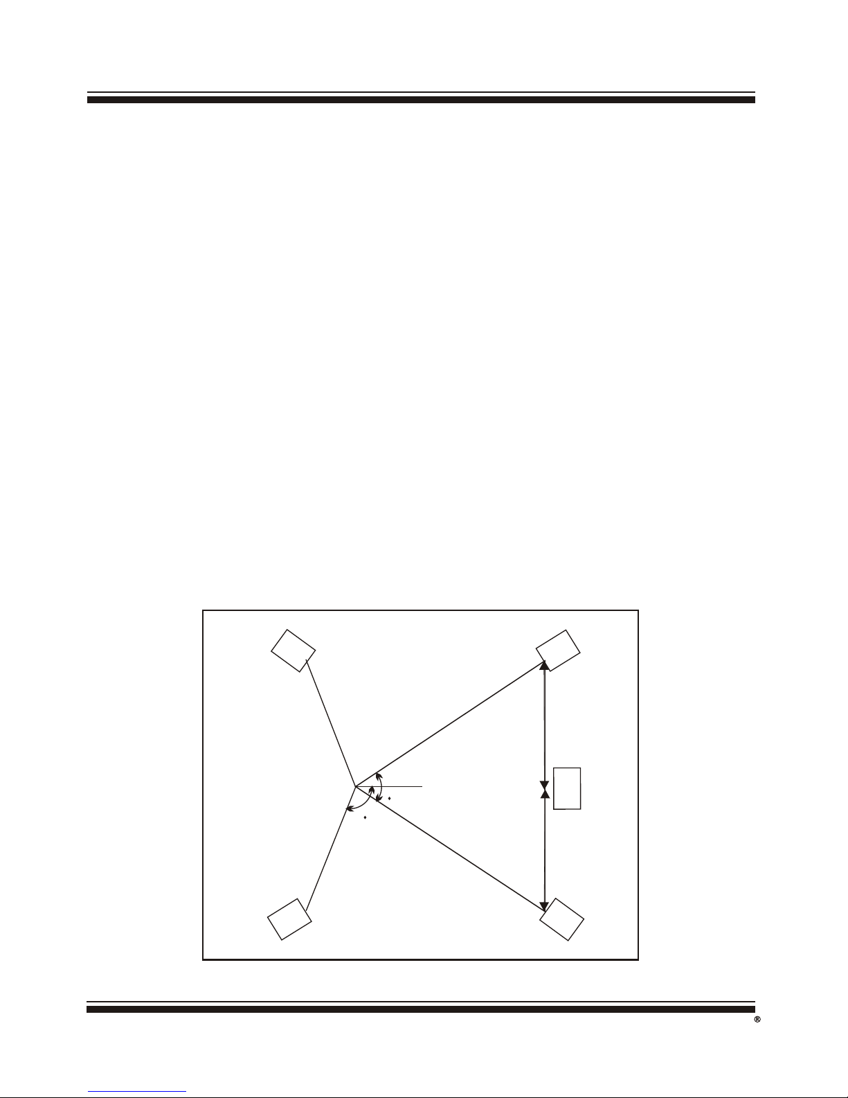
ROOM PLACEMENT: The SM 100Ak has a wide variety of placement options. Shown in Fig. 4 on page 4 is a typical stereo setup for near
to mid-field monitoring. Shown in Fig. 3 is a typical 5 channel setup.
The monitors should be angled to directly face the listener. The center of the high frequency transducer should be on-axis with the ear
level of the listener.
The low frequency compensation settings can be used when speakers are placed in close proximity to walls, corners and work surfaces.
LISTENING DISTANCE: The common listening position at mixing positions is generally 1 to 1.5 m for near field applications. For mid-field
applications, 2-3 m is more likely. The stereo listening angle is more a matter of personal preference, but we recommend the angle should
be around 60° as shown in Fig. 4 on page 4
MOUNTING OPTIONS: The SM 100Ak may be wall or floor mounted. (Optional) accessories are available.
CONNECTORS
•Audio: The SM 100Ak has one balanced TRS and one 3 pin balanced XLR input. (refer to Fig. 2: rear panel on page 1) The pin
configuration is shown in Fig. 5 on page 4. The wiring configuration for using unbalanced sources is also shown. (Please note that
we strongly recommend against using unbalanced inputs.)
•AC Power: This is a 3 pin IEC type socket (see Fig. 2: rear panel on page 1) with integral fuse holder. The fuse is rated as 0.6A SB.
Replace only with exact type and rating.
Installation •Fig. 3
FIG. 3
FL / FR : Front Left & Front Right Speakers
C : Center Speaker (on top of TV)
SL / SR : Surround Left & Right Speakers
6060
120120
FL FR
SL SR
C
1 to 1.5 m 1 to 1.5 m
The figure shows ideal seating arrangement..
Practically however, actual placement distances may differ.
Typical 5 Channel Set-up

Page 4
S
N
O
D
N
Y
E
O
SM 100Ak
OPERATION
•Connect the line level monitor signal from your mixer (or any other source) to the signal input on the SM 100Ak studio monitor using
balanced cables (¼” TRS / 3 pin XLR).
•Connect the supplied AC power cord to the IEC socket at rear panel.
•Keep the power switch at OFF position and turn down the master level on the front panel to minimum position.
•Switch on your mixer, but keep the master level control at minimum.
•Switch ON SM 100Ak. The blue power LED will light up. Ensure that the Input Sensitivity (Gain control at the rear panel) is set to 0dB
•Slowly turn up the Master level control of the SM 100Ak.
•Now, adjust the master volume on your mixer to a comfortably loud listening position.
Note
•Your SM 100Aks’ achieve their best bass response in a room that is optimized for bass reproduction. Factors such as room shape
and volume, absence of acoustical treatment can prove to be a bane for optimal sound reproduction from the SM 100Aks. Therefore
we have provided some compensation controls which you can use to optimize the frequency response of the speakers for any
particular room. For the effect of these 'tilts' please refer to Fig: 6-8 on page 6.
MAINTENANCE
No user serviceable parts inside the unit. All maintenance and repair work to be undertaken by qualified personnel only.
Fig. 4 & 5 •Operation •Maintenance
60°
SMA
10k
0
k
S00
A
M1
2. o 15t m
FIG. 4
Wiring configuration for use with unbalanced sources
1 2
3
3 pin XLR male
RCA
1 2
33 pin XLR male
R/ ” S
14T
2
1
3
1/4” TRS
1
2
3
Pin Signal
3 -
2 +
1 GND
3 pin XLR
FIG. 5

Page 5
S
N
O
D
N
Y
E
O
SM 100Ak
Troubleshooting
Symptom: Device remains 'OFF'
•Make sure that the power cord is securely seated in the IEC socket and plugged all the way into the AC outlet.
•Make sure that the AC outlet is live (check with tester).
•Remove power cord and check the Fuse. If blown, then replace with exact type and rating.
Symptom: Device is 'ON' but no audio output
•Is the master level control on the front panel turned up? The gain control on the rear panel may be at minimum position.
•Is the signal source turned up? Make sure that the signal level from the device preceding the SM 100Ak is high enough to
match the Input sensitivity (Gain control on rear panel).
•If either of the stereo pair is not producing sound, then switch the signal around. If the problem also switches sides, the
problem is not the monitor. It could be a bad signal cable, or no signal from the mixer.
Symptom: Distorted sound
•Ensure secure connectivity of the TRS / XLR.
•Reduce signal level at mixer or reduce gain control of SM 100Ak at rear panel.
•Please monitor the signal with headphones. Distorted sound in headphones indicate that the problem lies in the signal
source.
Symptom: Noise / Hum / Line interference
•Proper signal wiring between the mixer and the monitor eliminates the hum, buzz and all sorts of crackling noises. Make sure
all connections are secure.
•If unbalanced sources are used, wire the connectors such that the unbalanced ground of the source is connected to the
inverting pin (pin 3 for XLR, ring for TRS jack) and ground (pin 1 for XLR, sleeve for TRS jack). Improper cabling will result in
unsatisfactory audio reproduction. (please refer to Fig. 5 on page 4)
•If a CATV cable is connected to the system, and a persistent mains hum occurs, disconnect it. If the hum goes away call the
cable operator to check for proper cable grounding methods. Using BALUN transformers (1:1, isolated type) might solve the
problem.
•Make sure that the signal cable is not routed near AC cables.
•If a light dimmer or triac-based device exists on the same AC circuit as the monitor, buzzing noises may occur. AC Line filters
may eliminate the problem.
S
N
O
D
N
Y
E
O
SM 100Ak Page 6
Fig. 6, 7 & 8
FIG. 6
Effect of Switch:1
FIG. 7
Effect of Switch 2
Effect of Switch 3
Effect of Switches 2 & 3
FIG. 8
Effect of Switch:4

S
N
O
D
N
Y
E
O
Specifications
105 dB at 1m
80°(averaged between 5 ~ 14 kHz)
80 Hz ~ 200 Hz <3%
LF: 45 W HF: 45 W
< 0.04 %
2 way nearfield active monitor
composite poly-frame
HF : Magnetically shielded 26mm silk – dome ferrofluid cooled
tweeter with integral waveguide
(at 95 dB SPL) >200 Hz <1%
TRANSDUCER COMPLEMENTS
USABLE FREQUENCY RANGE
MAX. LONG TERM SPL, HALF SPACE
HORIZONTAL BEAM WIDTH
VERTICAL BEAM WIDTH
TOTAL HARMONIC DISTORTION
S/N RATIO (AT UNITY GAIN)
AMPLIFIER THD AT RATED POWER
INPUT LEVEL FOR 109 DB SPL AT 1M
GAIN CONTROL RANGE
VOLUME CONTROL RANGE
CMRR
SUBSONIC FILTER
CROSSOVER
BASS TILT
BASS ROLL-OFF
TREBLE TILT
CONTROLS : FRONT
CONTROLS : REAR
INDICATOR
PROTECTION
POWER REQUIREMENT
FINISH
MECHANICAL DIMENSION (W x H x D)
INTERNAL VOLUME/ NET WEIGHT
DESCRIPTION
LF : Magnetically shielded 6.5” Kevlar cone woofer in
Vented, through twin front-firing aerodynamic port
60 Hz ~ 22 kHz, (± 3 dB)
50 Hz ~ 30 kHz, (±10 dB)
109 dB at 1m
90°(averaged between 5 ~ 14 kHz)
85°(averaged between 5 ~ 14 kHz)
65 Hz ~ 200 Hz <3%
LF: 80 W HF: 40 W
> 90 dB, referred to full output
< 0.04 %
- 6 dBU
± 6 dB, with respect to U position
> 70 dB
> 65 dB
40 Hz, 12 dB/ octave
4th order, Linkwitz Riley, 1.5 kHz crossover freq.
- 2 dB , - 4 dB , - 6 dB @ 80 Hz
80 Hz, 6 dB/ octave
- 2 dB @15 kHz
Power Switch and Volume Control
Gain control, 4 DIP switches for bass/treble tilts & bass roll-off
Power ON /OFF
Over current, Overheat , RFI, Switch on/ off transients
230 V AC,± 10 % , 50 Hz
200 VA Max.
Die-cast aluminum
Black texture
230 mm x 335 mm x 300mm
13 Litre / 10.5 Kg
MECHANICAL
POWER CONSUMPTION
CABINET MATERIAL
INPUT
AMPLIFIER AND CROSSOVER
AMPLIFIER POWER BEFORE CLIPPING
SYSTEM
ENCLOSURE TYPE
OVERALL FREQUENCY RESPONSE
Manufactured by Sonodyne Technologies Pvt. Ltd, H.O.: 98 NB Block E New Alipore, Kolkata 700053, INDIA
Please visit us at www.sonodyne.com
A product of the Mukherjee Innovation Centre
Table of contents
Other Sonodyne Speakers manuals

Sonodyne
Sonodyne IWO Series User manual

Sonodyne
Sonodyne Avant 150 User manual

Sonodyne
Sonodyne Alaap User manual

Sonodyne
Sonodyne SPA 110P User manual

Sonodyne
Sonodyne Micro Series User manual

Sonodyne
Sonodyne SLX Series User manual

Sonodyne
Sonodyne MICRO 3002 User manual

Sonodyne
Sonodyne PM 4040 User manual

Sonodyne
Sonodyne Genie 1 User manual

Sonodyne
Sonodyne MICRO 3001 User manual


