Nitchi MH-5 User manual

NITCHI-MATIC
ELECTRIC CHAIN HOIST
MODELS
• MH5 • MHT5 • MHC5
TROLLEYS MECHANICAL JOINING TYPE
MODELS: MET5, MGT5 AND MPT5
Operating Instructions Booklet
The hoist operator must receive this operating instructions booklet!-
Thoroughly read this operating instructions booklet before operating the
trolley and electric chain hoist.
Carefully store this operating instructions booklet after reading it.
This operating instructions booklet contains important information that will be
necessary when inspecting and maintaining the trolley and electric chain hoist.
-
-
The hoist operator must read this operating instructions booklet!
-
The above information will be required when purchasing spare parts and when making inquiries.
Copy them from the name plate on the hoist and save them for future reference.
Customer’s notes:
N.B.
Model
Serial No.
Date Purchased

PREFACE
NITCHI products are made of the best selected materials, and processed through up-to-date
streamlined production facilities by skilled NITCHI engineers under severe quality control.
To assure absolute safety, dependability and satisfactory performance, rigid nal inspections and tests
in accordance with our own standards are carried out on the NITCHI products before they leave the
plant.
WARRANTY
NITCHI products are guaranteed to be free from any defects in materials or workmanship. lf any part
or parts proves defective within 1 year from the date of purchase, we will replace the part no-charge,
F.O.B. Osaka, Japan, provided the part claimed defective is returned to our factory through authorized
NITCHI Distributors or Agents with transportation prepaid. However, we reserve the right to decline res-
ponsibility for these which repairs are made or attempted by others or misused or carelessly operated
or maintained.
SAFETY PRECAUTIONS
Misuse of an electric chain hoist can cause dangerous situations such as dropping of the hoisted load
or electrical shocks. To ensure proper use, it is essential that this instructions booklet and the manual of
any other equipment that is to be used at the same time be read and fully understood before installing
or servicing the equipment. Before use, the operator must be fully familiar with; the equipment, with
all of the safety procedures and the warning provisions. In this instructions booklet you nd two cate-
gories of warning: “DANGER”and“CAUTION” .
EXPLANATION OF THE WARNINGS
DANGER DANGER are incorrect usages that can lead to death or serious injuries.
CAUTION CAUTION are incorrect usages that can lead to light injuries or property damage.
Situations classied as "CAUTION “ may result in serious conditions in some cases.
Precautions must be obeyed no matter what category they come under.
!
!
• Serious injuries are permanent disabilities, wounds that require hospitalization or prolong
outpatient treatment such as; loss of eyesight, injuries, burns, electrial shocks, and broken bones.
• Light injuries mean burns and electrical shocks that do not require hospitalization and prolong
outpatient treatment.
• Property damages are major losses to the building, equiment or machinery.
EXPLANATION OF THE SYMBOLS
Procedures that are forbidden (not allowed) during operation of the product. Examples are shown in
drawings or expressed in words near the symbol.
Procedures that are mandatory (that must be carried out) during the operation of the product.
Examples are shown in drawings or expressed in words near the symbol.
This symbol expresses that an eective ground wire is absolutely necessary .
Details will be shown in circuit diagrams, drawings or expressed in words near the symbol.
This symbol gives warning of electrical shocks that can occur when handling the product.
Details will be shown in drawings or expressed in words near the symbol.
This instructions booklet must be stored where it can be easily accessed by the user.
PROHIBITED
MANDATORY
GROUND
CONNECTION
ELECTRIC
HAZARD
N.B.

1. OVERALL HANDLING
2. IMPORTANT!!
The following warnings and safety procedures are essential for avoiding possible bodily injury and
property damage.
2.1 BASIC SAFETY PROCEDURES
CAUTION
NEVER lift more than the rated load marked on the hoist.
NEVER use the hoist to lift, support or transport people.
NEVER lift or transport loads over or near people.
ALWAYS read the operation and safety instructions.
2.2 SAFETY PROCEDURES PRIOR TO USE:
CAUTION
ALWAYS The operator of the hoist must be a person who is completely familiar
with all safety and operation procedures.
ALWAYS Check the hoist before use and conrm that the load chain is well
lubricated.
ALWAYS Check the brake before use.
ALWAYS Check the safety latches to see if they work properly. Broken and missing
safety latches must be replaced immediately.
ALWAYS Use genuine NITCHI parts and chains.
NEVER Modify the hoist.
NEVER Use modied or deformed hooks.
NEVER Use a hoist when malfunction, unusual performance, damage or
extensive wear are found.
NEVER Abuse the over-hoisting/over-lowering limit switch mechanism by using it
regularly.
NEVER Remove or obscure the warnings and nameplate on the hoist.
DANGER
The unit (electric chain hoist and trolley) must be operated only by people who fully understand the operating instruc-
tions booklets and the precautions on the warning name plates. People without the necessary qualications must not
operate the unit or carry out hook and sling connecting operations. lnspect the unit before operating it, and carry out
periodical inspections. Never hoist/lift people!
!
!
!

SAFETY PROCEDURES DURING OPERATION
CAUTION
ALWAYS Set the load properly in the hook.
ALWAYS Conrm that the safety latch has closed completely.
ALWAYS Take up the slack of the load chain and sling carefully, and make the initial
load lifto shock as small as possible.
ALWAYS Use a hoist within the“ Duty rating“ , ED % or time rating.
ALWAYS Avoid excessive inching and make sure that the hoist motor completely
stops before reversing the operating direction.
NEVER Allow your attention to be diverted when operating the hoist and never leave a suspended
load unattended.
NEVER Operate the hoist unless the load is centered underneath it.
NEVER Use the hoist with twisted, kinked, damaged or worn chain and never
attempt to lengthen the load chain.
NEVER Use the load chain as a sling and never apply the load to the tip of the hook.
NEVER Use the load chain so that it comes in to contact with an edge.
NEVER Allow the chain or hook to be used as a ground for welding and never touch them with
live welding electrodes.
NEVER Abuse the friction clutch by using it frequently. lmproper use can severely
damage the hoist and lead to serious injuries.
NEVER Pull on the pendant control cable.
MAINTENANCE SAFETY PROCEDURES
CAUTION
ALWAYS Have a qualied service person inspect the hoist periodically.
ALWAYS Clean the hoist thoroughly and keep the load chain well lubricated.
NEVER Attempt to extend, repair or weld the load chain.
NEVER Touch live electrical parts.
!
!

STANDARD SPECIFICATIONS................................................................................................................................................................ 1
INSTALLATION............................................................................................................................................................................................... 6
Connecting the Chain bucket................................................................................................................................. 6
Lubrication...........................................................................................................................................................................7
Circuit breakers..................................................................................................................................................................7
Power source cabIe........................................................................................................................................................ 8
Power source cabIe specications........................................................................................................................8
Adjusting the Trolley width....................................................................................................................................... 9
Setting the Trolley onto the beam........................................................................................................................10
Connecting the hoist to the trolley......................................................................................................................11
Connecting the Power source cabIe....................................................................................................................12
lnspection After lnstallation......................................................................................................................................13
INSPECTION & MAINTENANCE.......................................................................................................................................................... 14
INSPECTION BEFORE USE......................................................................................................................................................................14
MONTHLY AND ANNUAL INSPECTIONS...................................................................................................................................... 14
INSPECTION POINTS..................................................................................................................................................................................15
Hook & Chain lnspection.............................................................................................................................................17
ADJUSTING THE BRAKE............................................................................................................................................................................18
Adjusting the electromagnetic brake.................................................................................................................18
HOW TO USE THE CHAIN LIMIT GOUGE.....................................................................................................................................19
TROUBLESHOOTING..............................................................................................................................................................................20
CIRCUIT DIAGRAM.....................................................................................................................................................................................21
SPARE PARTS TABLE AND SPARE PARTS CODE TABLE........................................................................................................32
3. CONDITIONS OF USE
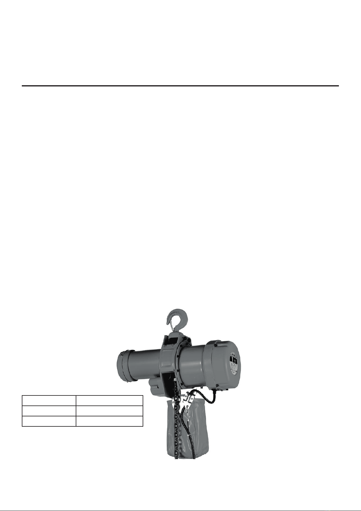
The MH-5 Series electric chain hoists and trolleys are designed for the vertically lifting, lowering and ho-
rizontal transportation of loads by operating the pendant push button switch, and must be used within
the following conditions:
1. Power source : As specied on name plate of the electric chain hoist, and motorized trolley.
2. Trolley beam : Trolley to be used only on the designated beams.
3. Temperature : / 15°C -/+ 40°C
4. Humidity : Under 90%
5. Protection : Hoist: IP43 (Do not use in rain or dusty environments.)
Trolley: IP42 (Do not use in rain or dusty environments.)
6. Enclosure status: Do not use in ambient conditions that contain steam or explosive gases.
7. Duty rating: Model MH5 30 minutes
Model MHT-5 20/20 minutes (slow / fast)
Model MHC-5 15 minutes
Model M-ET-5 30 minutes
8. Grade: Models MH-5, MHT-5, MHC-5, M-ET-5 M4 & M5
CONTENTS

1
STANDARD SPECIFICATIONS
Hook Suspended Type Electric Chain Hoist
MH-5 0.5-3 ton
Diagrammatic only
MH-5 / 5 ton
Diagrammatic only
STANDARD SPECIFICATIONS: MH-5 Electric Chain Hoist
Item No.
Rated
load
(ton)
Lift
(m)
Hoisting Speed
(m/min)
Hoist Motor 3-phase Load chain
Test
load
(ton)
Minimum
headroom
(Max.) G
(mm)
Net
Weight
(ap-
prox.)
(=kg)
Grade
Output (kW) Ins.
Class
Rating
(min) % ED Dia.
(mm)
Nos. of
falls
50Hz 60Hz 50Hz 60Hz
MH5005 0.5
4.0
8.6 10 0.83 1.0
B 30 40
7.1 1 0.625 550 53 M5
MH5010 1 6.2 7.3 1.17 1.4 7.1 1 1.25 560 55 M4
MH5020 2 6.7 7.9 2.5 3.0 11.2 1 2.5 725 100 M5
MH5030 3 4.4 5.2 2.5 3.0 11.2 1 3.75 765 102 M4
MH5050 5 2.6 3.1 2.5 3.0 11.2 2 6.25 925 130 M4
Item No. Rated load
(ton)
Major dimensions (approx.) (mm)
A B D E F P Q S (m)
MH5005 0.5 265 285 152 106 20 690 220 3.6
MH5010 1 285 285 152 106 25 690 220 3.6
MH5020 2 335 335 195 127 30 860 235 3.8
MH5030 3 335 335 195 127 36 880 235 3.8
MH5050 5 335 335 247 93 43 960 290 3.8
Notes:
1. Values marked will dier in accordace with the height of lift.
2. The specications in the above tables are subject to change without notice.
The design, materials and specications are subject
to change for improvements without notice

2
Electric Chain Hoist with Motorized Trolley
Standard Specications: EMT-MH-5 Electric Chain Hoist with Electric Trolley
EMT-MH-5 0.5 - 3 ton
Diagrammatic only
EMT-MH-5 5 ton
Diagrammatic only
Beam drawing
Item No.
Ra-
ted
Load
(ton)
Lift
(m)
Hoist Motor Traversing
Speed (m/
min)
Trolley motor
Test
Load
(ton)
Minimum
Headroom
(Max.) G
(mm)
Net
Weight
(approx.)
(=kg)
Hoisting
Speed (m/min)
3-phase Load chain 3-phase
Breadth of
Beams b
(mm)
Mini-
mum
radius
for curve
(m)
Output (kW)
Ins.
Class
Ra-
ting
(min)
Dia.
(mm)
Nos.
of
falls
Out-
put
(kW)
Ins.
Class
Ra-
ting
(min
50Hz 60Hz 50Hz 60Hz 50Hz 60Hz
MHE5005 0.5
4.0
8.6 10.0 0.83 1.0
B 30
7.1 1 20
(10)
24
(12) 0.2
E 30
75, 100, 125 1.0 0.625 535 84
MHE5010 1 6.2 7.3 1.17 1.4 7.1 1 20
(10)
24
(12) 0.2 75, 100, 125 1.0 1.25 545 86
MHE5020 2 6.7 7.9 2.5 3.0 11.2 1 20
(10)
24
(12) 0.4 100, 125, 150 1.0 2.5 725 153
MHE5030 3 4.4 5.2 2.5 3.0 11.2 1 20
(10)
24
(12) 0.4 100, 125, 150 1.5 3.75 805 172
MHE5050 5 2.6 3.1 2.5 3.0 11.2 2 20
(10)
12
(24)
0.4
(0.75) 125, 150, 175 1.5 6.2 975 219
Item No.
Rated
Load
(ton)
Major Dimension (approx.) (mm)
A B D E F H I J K L M N U PQS
(m)
MHE5005 0.5 265 285 152 106 20 b/2+280 b/2+230 127 240 32-t2 b-49 69 99+t2 675 220 4.0
MHE5010 1 285 285 152 106 25 b/2+280 b/2+230 127 240 32-t2 b-49 69 99+t2 675 220 4.0
MHE5020 2 335 335 195 127 30 b/2+325 b/2+235 159 300 33-t2 b-70 95 121+t2 860 235 4.0
MHE5030 3 335 335 195 127 36 b/2+330 b/2+240 180 340 37-t2 b-76 110 134+t2 920 290 4.0
MHE5050 5 335 335 247 93 43 B/2+330 b/2+245 204 390 38-t2 b-80 13 158+t2 1,010 290 4.0
Notes:
1. Values marked will dier in accordace with the height of lift.
2. The specications in the above tables are subject to change without notice.
3. The specications in ( ) are for electric trolley with half-speed or high-speed.
4. Please refer to the beam drawing for dimensions b and t.
The design, materials and specications are subject
to change for improvements without notice

3
Electric Chain Hoists with Geared Trolley or Plain Trolley
MHG-5 0.5-3 ton
Diagrammatic only MHG-5 5 ton
Diagrammatic only
Beam drawing
Item No.
Rated
load
(ton)
Lift (m)
Hoisting
Speed (m/
min)
Hoist Motor 3-phase Load Chain
Test
Load
(ton)
Breadth of
Beams b
(mm)
Mini-
mum
radius
for curve
Minimum
Headroom
(Max.) G
(mm)
50Hz 60Hz
Output (kW)
Rating
(min)
Dia.
(mm)
Nos.of
falls
50Hz 60Hz
MHG5005
MHP5005 0.5
4.0
8.6 10.0 0.83 1.0
30
7.1 1 0.625 75,100,125 1.0 515
MHG5010
MHP5010 1 6.2 7.3 1.17 1.4 7.1 1 1.25 75,100,125 1.0 525
MHG5020
MHP5002 2 6.7 7.9 2.5 3.0 11.2 1 2.5 100, 125, 150 1.2 710
MHG5003
MHP5030 3 4.4 5.2 2.5 3.0 11.2 1 3.75 100, 125, 150 1.5 770
MHG5050
MHP5050 5 2.6 3.1 2.5 3.0 11.2 2 6.25 125, 150 175 1.5 955
Item No.
Ra-
ted
load
(ton)
Major Dimensions (MHG-5 . MHP-5 MHG-5 MHP-5
A B D E F J K L M N U P
Q
S
(m)
L
(m)
H (mm) I
(mm)
T
(mm)
Net
Weight
(=kg)
H . I
(mm)
Net
Weight
(=kg)
MHG5005
MHP5005 0.5 265 285 152 106 20 110 206 24-t b-42 62 80+t 655 220 3.6 4.0 b/2+189 105 72+t 71 105 61
MHG5010
MHP5010 1 285 285 152 106 25 110 206 24-t b-42 62 80+t 655 220 3.6 4.0 b/2+189 105 72+t 73 105 63
MHG5020
MGP5030 2 335 335 195 127 30 140 262 28-t b-63 83 102+t 845 235 3.8 4.0 b/2+150 127 115+t 126 127 116
MHG5003
MHP5030 3 335 335 195 127 36 160 306 27-t b-63 107 126+t 885 235 3.8 4.0 b/2+150 133 118+t 139 133 130
MHG5050
MHP5050 5 335 335 247 93 43 172 329 35-t b-76 110 134+t 990 290 3.8 4.0 b/2+339 166 130+t 185 166 175
STANDARD SPECIFICATIONS : MHG-5 Electric Chain Hoist with Geared Trolley & MHP-5 Electric Chain Hoist with Plain Trolley
Notes:
1. Values marked will dier in accordance with the height of lift.
2. The specications in the above tables are subject to change without notice.
3. Please reler to the beam drawing for dimensions b and t2.
The design, materials and specications are subject
to change for improvements without notice

4
Hook Suspended Type 2-Speed Electric Chain Hoist
MHT-05 0.5 - 2.5 ton
Diagrammatic only
MHT-5 / 5 ton
Diagrammatic only
Item No.
Ra-
ted
Load
(ton)
Lift
(m)
Hoisting Speed (m/min) Hoist Motor 3-phase Load Chain
Test
Load
(ton)
Minimum
Headroom
(Max.) G
(mm)
Net
Weight
(ap-
porox.)
(=kg)
Grade
Fast Slow Output (kw)
Ins.
Class
Rating (min)
% ED Dia.
(mm)
Nos.
of
falls
50Hz 60Hz 50Hz 60Hz
Fast Slow
Fast Slow
50Hz 60Hz 50Hz 60Hz
MT5005 0.5
4
8.0 9.4 1.9 2.2 0.83 1.0 0.21 0.25
B 20 20 25
7.1 1 0.625 550 55 M5
MT5010 1 4.3 5.0 1.0 1.2 0.83 1.0 0.21 0.25 7.1 1 1.25 560 65 M4
MT5020 2 4.8 5.6 1.2 1.4 1.83 2.2 0.46 0.55 11.2 1 2.5 725 103 M5
MT5025 2.6 3.8 4.4 1.0 1.1 1.83 2.2 0.46 0.55 11.2 1 3.125 765 105 M4
MT5050 5 1.9 2.2 0.5 0.6 1.83 2.2 0.46 0.55 11.2 2 6.25 925 133 M4
STANDARD SPECIFICATIONS: MHT-5 2-Speed Electric Chain Hoist (Single-voltage)
Item No. Rated Load
(ton)
Major Dimension (approx.) (mm)
A B D E F PQ S (m)
MT5005 0.5 305 285 152 106 20 795 220 3.6
MT5010 1 305 285 152 106 25 795 220 3.6
MT5020 2 365 335 195 127 30 860 235 3.8
MT5025 2.5 365 335 195 127 36 880 235 3.8
MT5050 5 365 335 247 93 43 960 290 3.8
Notes:
1. Values marked will dier in accordance with the height of lift.
2. The specications in the above tables are subject to change without notice.
The design, materials and specications are subject
to change for improvements without notice

5
Hook Suspended Type Single-Phase Electric Chain Hoist
MHC-5 0.5-1 ton
Diagrammatic only
STANDARD SPECIFICATIONS: MHC-5 Electric Chain Hoist (Single-phase)
Item No.
Rated
Load
(ton)
Lift (m)
Hoisting Speed
(m/min) Hoist Motor 1-phase Load Chain Test
Load
(ton)
Minimum
Headroom
(Max.) G
(mm)
Net
Weight
(approx.)
(=kg)
Grade
50Hz 60Hz Output
(kW)
Rating
(min) % ED Dia
(mm)
Nos. of
falls
MC5005 0.5 4.0 5.4 6.4 0.62 15 25 7.1 1 0.625 550 58 M5
MC5010 1 2.7 3.2 1 1.25 560 58 M4
Item No. Rated Load
Major Dimensions (approx.) (mm)
A B D E F P Q S (m)
MC5005 0.5 305 285 152 106 20 690 220 3.6
MC5010 1 305 285 152 106 25 220
Notes:
1. Values marked will dier in accordance with the height of lift.
2. The specications in the above tables are subject to change without notice.
The design, materials and specications are subject
to change for improvements without notice

6
CONNECTING THE CHAIN BUCKET
INSTALLATION
PROHIBITED
MANDATORY
!
• Do not modify the chain bucket assembly.
• Always attach the chain bucket assembly before
raising the hoist into position.
DANGER
!
M6 x 20
Unloaded side
Chain bucket pin
Chain bucket
1. Connect the chain bucket assembly with
the chain bucket pin and M6 X 20 bolt.
2. Feed the load chain into the chain bucket
gradually and neatly from th end.
3. The load chain may tangle and the hoist
may not operate correctly when the load
chain is placed into the chain bucket as-
sembly in one bundle.
4. The inside of the chain bucket assembly
must be cleaned periodically when the
hoist is used in an area where dust and
foreign matter can enter the chain bucket
assembly.
Open the split pin as shown in the drawing.
Chain buckets dimensions (mm)
Steel Chain buckets dimensions (mm)
Chain bucket application table:
No. A B C D
1 260 170 150 65
2 365 200
3 350 240
185 85
4420 260
5 65
No. A B C D E
S1 500 200 200 300 250
S2 600 200 200 300 300
S3 700 220 200 340 350
S4 800 220 200 340 450
S5 900 220 200 340 550
S6 1050 220 200 420 600
S7 1150 220 200 420 700
Rated
Load (t)
Load Chain
diameter x
nos. of fall
Model
Lift (m)
0.5 - 1 7.1 x 1 MH-5 MHC-5
MHT-5 S1 -
2 - 3 11.2 x 1 MH-5
MHT-5 4 S1 S3
5 11.2 x 2 MH-5
MHT-5 4 S1 S2 S3 S4 S5 S6
3
3
1 2
2 5
4 5
5
6 7 8 9 10 11 12 13 14 15 16 17 18
S2
19 20 21 22 23 24 25
Table 1
Table 2
Table 3
N.B. The series chain buckets are made of steel.
S1

7
LUBRICATION
When the gear box section of the Motorised trolley is disas-
sembled, add an extra coat of heavy duty grease (disulde
molybdenum grease) to the gears. The gear box section
normally does not need to be regularly lubricated.
Paint the gear teeth section of the Gear
wheel and Pinion with cup grease.
1. The product is lled with lubrication oil before
shipment, it is not necessary to add oil on site. Make
a small hole in the oil cap, as illustrated on the right,
so that the internal pressure of the gear casing does
not increase during operation.
2. Check the oil level during the periodical inspection.
Add oil in the gear casing if the level is low. Oil shor-
tage or low - level oil generates abnormal noise and/
or malfunction of the mechanical load brake. See
the table below for replacing or replenishing oil.
3. Be sure to apply oil to the load chain.
Machine oil or gear oil is applicable.
1. Always install a circuit breaker.
The circuit breaker must be exclusively for the hoist and independent from other machinery.
2. Select an adequate capacity circuit breaker from Table 5.
Gear wheel
Pinion
Oil leber
Oil extractos
(plug)
Oil cap
Oil extractors (plug)
Oil of adequate quantity Oil extractors (plug)
Type of hoist
Capacity
MH-5. MHT-5
MHC5
0.5-1t
MH-5
2-5 t
MHT-5
2-5 t
Applicable
oil Brand and
lling quantity
JXTG Energy
CF-30
0.8 Liters
JXGT Energy
CF-30 1.5
Liters
Showa Shell
Sekiyu Tonna
S M220 1.5
Liters
Table 4
Table 5
Applicable Oil and Adequate Quantity
CIRCUIT BREAKERS
Model Rated load (t) Hoist motor (kW)
50Hz / 60Hz Traversing motor (kW) Circuit breaker (A)
MH-5
MHG-5
MHP-5
0.5 0.83 / 1.0 - 5
1.0 1.17 / 1.4 - 10
2 - 5 2.5 / 3.0 -
MHE-5
0.5 0.83 / 1.0 0.2 10
1 1.17 / 1.4
2 - 5 2.5 /3.0 0.4 15
5 1 0.75
MHT-5 MHTG-5 MHTP-5
(Low speed/High speed)
0.5 . 1 0.21/0.83/0.25/1.0 5
2 - 5 0.46/1.83/0.55/2.2 - 10
MHTE-5
(Low speed/High speed)
0.5 - 1 0.21/1.83/0.25/1.0 0.2 10
2 - 5 0.46/1.83/0.55/2.2 0.4
5 1 0.75 15
MHC-5 · MHCG-5 · MHCP-5 0.5 • 1 0.62 - 15
1 High - speed (20/24 min. 50/60 Hz) trolley model.

8
POWER SOURCE CABLE
POWER SOURCE CABLE SPECIFICATIONS
1. With electric chain hoists that use the electrical cable power feeding method, always be sure to use
the appropriate sized cabtyre cable (tough-rubber sheathed cabIe).
2. Use a larger size cabtyre cable when the cable length is long, and when there is a possibility
that the hoist and the motorized trolley will be operated together at the same time.
3. Please refer to Table 6 for the specications of long cabtyre cables.
The below table is applicable for hoists with 380 to 440 volt for 3 phase models
and 200 volt for single phase models.
Length and Size of Cable
Model Rated load (t) Hoist motor (kW) 50Hz / 60Hz Traversing motor
(kW)
Cable size (mm) & MAX. length
Cable length (m)
MH-5
0.5 0.83 / 1.0 -
1 1.17 / 1.4 -
2 - 5 2.5 / 3.0 -
MHE-5
0.5 0.83 / 1.0
0.2
1 1.17 / 1.4
2 - 5
2.5 / 3.0
0.4
5 1 0.75
MHT-5 (low speed/
high speed)
0.5 - 1 0.21 / 0.83 / 0.25 / 1.0 - 1.25 MAX 118.7 m
2 - 5 0.46 / 1.83 / 0.55 / 2.2 -
MHTE-5
(Low speed/ High
speed)
0.5 - 1 0.21 / 0.83 / 0.25 / 1.0 0.2 1.25 MAX. 86 m
2 - 5
0.46 / 1.83 / 0.55 / 2.2
0.4
5 1 0.75
MHC-5 MHCG-5
MHCP-5 0.5 - 1 0.62 -
2.0 MAX. 48.6 m
1.25 MAX. 81.3 m
10 8020 30 40
1.25 MAX. 109.9 m
1.25 MAX. 77.1 m
2.0 MAX. 57.3 m 3.5 MAX. 103.2 m
3.5 MAX. 87.6 m
2.0 MAX 87.6 m
50 60 70
2.0 MAX. 46.1 m
1.25 MAX. 61.3 m
3.5 MAX. 83 m
2.0 MAX. 52.1 m
2.0 MAX. 60 m
2.0 MAX. 64.4 m
2.0 MAX. 80.6 m
3.5 MAX. 93.9 m
3.5 MAX. 108.2 m
3.5 MAX. 116.1 m
Table 6
1 High - speed (20/24 min. 50/60 Hz) trolley model.

9
ADJUSTING THE TROLLEY WIDTH
Adjust the width between the trolley wheels as follows:
1. Remove the Hexagonal nuts, and remove the side-plate.
2. While referring to Table 7, move the appropriate numbers of Adjusting collars
to the both sides of the Top holder.
3. Tighten the Hexagonal nuts for the Stay bolts.
4. Conrm that the Top holder is positioned directly under the trolley beam.
0 pieces of Adjusting collars inside of the
Side-plated
4 pieces of Adjusting collars inside of the Side-Plates
2 pieces of Adjusting collars inside of the
Side-plates
Incorrect installation of the adjusting collars
Adjusting Collars
Applicable beam widths
(mm)
0 pieces 2 pieces 4 pieces
0.5 - 1 75 100 125
2 - 3 100 125 150
5 125 150 175
Rated load (t)
Collars inside of
the side plate
Table 7
Wheel Wheel
Trolley beam
Side-plate Side-plate
Stay bolt and Hexagonal nut
Adjusting collars on the outside an inside of the Side Plates
Top-holder
Stay bolt and hexagonal nut
Adjusting collars on the outside of the side plates.
Adjusting collars on the inside of the Side plates. Adjusting collars all on one side

SETTING THE TROLLEY ONTO THE BEAM
PROHIBITED
!
• The trolley must be installed onto the trolley
beam only by qualied people with the neces-
sary knowledge.
DANGER
lnserting an assembled trolley from the end of the trolley beam:
• Remove the Stoppers at the end of the trolley beam, and insert the trolley.
• Replace and positively secure the stoppers.
1.
2.
3.
How to install the trolley when the assembled trolley can not be inserted from
the end of the trolley beam:
• Remove the Hexagonal nuts from the Stay bolts.
• Dismount the Plain-side plate.
• Set the Geared wheels on to the tread section of the trolley beam.
• While holding the Geared wheels in position, insert the Plain-side plate so that the Plain
wheels will be in position on the tread section of the trolley beam.
• Firmly tighten the Hexagonal nuts of the Plain-side plate side of the Stay bolts.
When the trolley beam is curved, install the trolley so that the geared wheels
are on the outside of the curve.
Motorized trolley Geared trolley
Stopper
Plain-side plate
Stay bolt
Motor
Gear wheel
Hand wheel
Gear wheel
Trolley beam
Trolley beam
Gear-side plate
Gear wheel
Gear wheel on the tread section
of the trolley beam.
Appearance of trolley correctly
installed on to trolley beam.
10

11
CONNECTING THE HOIST TO THE TROLLEY
Connecting the electric chain hoist to a geared trolley (plain trolley):
Geared trolley (Plain trolley)
Electric chain hoist
Split pin
Insert the Split pin
into the hole of the
Top hook pin.
Open the Split pin as
shown in the drawing.
Insert into the hole
Top hook pin
Insert the Top hook pin
as shown in the drawing.
Connect the trolley to the electric
chain hoist as shown in the drawing,
and be sure that the trolley and elec-
tric chain hoist are both facing the
correct direction.
Direct-coupled electric trolleys are delivered coupled to hoists and no connecting procedures are necessary.

12
CONNECTING THE POWER SOURCE CABLE
PROHIBITED
!
• The hoist must be eciently grounded, and an inde-
pendent circuit breaker of the appropriate capacity
must be installed in the power source system.
DANGER
The power source systems of hoists connected to trolleys are as follows:
lnstall a messenger wire ( 6 mm steel cable) parallel to the trolley beam.
Hang the power source cable from the messenger wire with cable carriers, and be
careful not to twist the power source cable.
lnstall cable carriers at every 1.5 meters length of the power source cable.
The connections of the Power source cable must only be made at the Hoist, Termi-
nal box and Power source switch. Do not use Power source cables that are lengthe-
ned with connections.
The following power source feeding method can be used in place of the Messen-
ger wire method. Please consult an electrician for the most appropriate method for
your hoist: CABLE CARRIER METHOD,
TROLLEY DUCT METHOD &
TROLLEY WIRE METHOD
1.
1.
2.
3.
Messenger wire
Trolley beam
Power source switch
Cable carrier Terminal box
ELECTRIC
HAZARD

13
INSPECTION AFTER INSTALLATION
ELECTRICAL WIRING
Procedures to be carried out before the power source switch is turned "ON".
1. The load chain must always be free from twists. When the hoist lifts on two or more falls of load
chain, twist can arise from the bottom hook being accidentally turned over through the load chain.
2. While the hoist is not under a load, lubricate the whole length of the load chain with machine oil,
and be sure to give the contact points between the links extra coatings.
CONNECTING THE POWER SOURCE
- Always connect the power source at a Terminal box ( with Main circuit breaker).
Purchase and install the Terminal box before using the hoist.
- Connect the power source as shown in the circuit diagram.
Connect one of the three wires to the grounded terminal “S”.
- Eectively ground the Earth wire (Green/Yellow).
Extra coating of machine
oil at contact points
Hoist with two falls of
load chain
!
!
• For the prevention of danger, always turn the main power source o at
the Terminal box when the electric chain hoist is not in use!
• The power source must be turned o before attempting to change the
phases of the power source to correct a negative phase connect.
DANGER
DANGER
3-Phase power source
Ground
Power source cable
Terminal box
PROHIBITED
ELECTRIC
HAZARD
- In reverse phase connection, 'Warning relay of Negative phase' will function and can not operate.
(Conrm that wire "S" is connected to the grounded terminal.)
- A negative phase connection can be corrected by interchanging 2-Phases "R-T" of the
3-Phase power source (Conrm that wire "S" is connected to the grounded terminal.)

14
INSPECTION & MAINTENANCE
INSPECTION BEFORE USE
MONTHLY AND ANNUAL INSPECTIONS
!
• When inspecting the hoist, turn the power source“OFF”and hang out
a sign that distinctly indicates that it is under inspection. lnspect the
hoist while it is not under a load. Consult the authorized NITCHI dealer
or distributor from where the hoist was purchased when repairs or
replacement parts are required.
DANGER
MANDATORY
Daily, monthly and annual inspections are essential for ensuring a long and safe lifetime of the hoist.
All inspections and repairs must be carried out by competent responsible people authorized by the person
in charge of the hoist. Always check the following safety procedures when inspection and maintenance work
are carried out on the hoist:
While the hoist is not under a load, conrm that the whole length of the load chain is well lubricated. When
the load chain requires lubrication, be sure to give the contact points between the links extra coatings of
machine oil. The load chain must not be deformed and elongated and it must be free of twists and kinks.
Check especially carefully when the hoist lifts on two or more falls of load chain.
The hooks must not be elongated and deformation must be within the limits indicated in
Table 11.
The safety latches must all be in good condition and moving smoothly.
The pendant push button switch must function properly and smoothly.
While the hoist is not under a load, conrm that the limit switch and brake systems are
functioning correctly.
The trolley and/or crane must be free of faults that prevent smooth and safe operation.
The components of the hoist will eventually wear from use. Tables 8 and 9 give inspection points that are
essential for insuring a long and safe lifetime of the hoist.
MONTHL Y INSPECTION
lnspect the hoist once a month, and keep a record of all inspections and repairs on le.
ANNUAL INSPECTION
Check all sections of the hoist especially carefully once a year, and keep detailed records of the inspections
and repairs on le.

15
INSPECTION POINTS
MH-5 SERIES HOISTS Table 8
Section Check points Proper sondition
Body
External view No crack of deformation
Abnormal sound Motor and other parts sound normal.
Side-plates No wearing deformation
Gears and bearings No wearing and crack. Well lubricated with oil.
Load sheave No wearing and crack
Hooks
Opening Same as recorded dimension“A”for new hook.
Holders No crack and deformation.
Bottom swivel hook Rotates smoothly on a thrust ball bearing.
Rivets for holder No wear or deformation
Load chain Dimensions Refer to the table 12.
Visual condition No rust, cracks, wear or deformation
Lubricant
Gear teeth Sucient oil
Load chain Well lubricated with machine oil along the
whole length, particulary at the contact points.
Limit mechanism Limit switch Motor stops when handle is pushed up. Test
lifting and lowering without a load
Stop - holder Bolts and nuts rmly tightened. No crack.
Brake mechanism Brake
The brake must function positively. When the
rated load is lifted, the amount of slippage of
the brake must be within 1 % of the distance
the hoist can lift in 1 minute (Refer to the
“Lifting speed”on Page 1 to 5)
Electrical components
Power source cable and pendant control
cable.
No breakage and damage of the rubber-cover-
ed cables. No disconnection.
Push-button switch Contact points functioning positively.
Switch box Limit switch, electromagnetic contactor functi-
oning correctly.
Motor No humming and over-heating.
Insulation resistance lnsulation resistance exceeds 2M Ω by DC 500V
Megger.
Others
Bearings Properly and smoothly engaging with shafts.
Chain collecting bucket Inside of the chain bucket free of rust, dirt,
grease and other foreign matter.
Bolts, nuts, etc. All in good condition and securely in position.
Name-plate (mark-plate) Clearly observable.
Other manuals for MH-5
1
This manual suits for next models
12
Table of contents
Other Nitchi Chain Hoist manuals
Popular Chain Hoist manuals by other brands

Paccar Winch
Paccar Winch Gearmatic GH30B Service and maintenance manual

Planeta
Planeta PKB Series Operation and maintenance manual

Yale
Yale CPA Series Translation of original operating instructions

McBULL
McBULL 9354 manual

MetalTech
MetalTech BuildMan I-BMDPL Replacement guide

Hitachi
Hitachi L Series Service manual