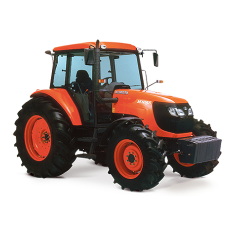
Nitro motors 110cc User manual

1
Preface
Dear user:
Thank you for your selection of our Nitro Motors 110cc Tractor
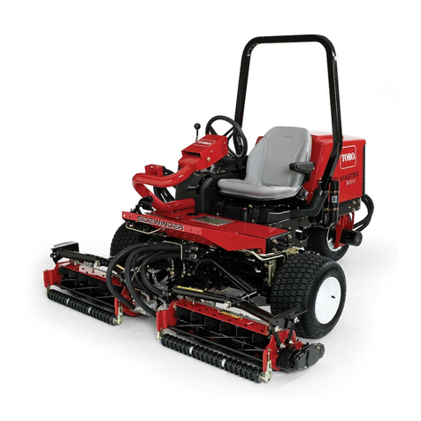
Our Nitro Motors 110cc Tractor car designed with the latest technology is suitable for recreation and competition. It is equipped with single-cylinder 4-stroke
air-cooled engine and convenient electric start. It is fixed with front and rear shock absorber to improve comfort during driving. Its front wheel is fixed with drum
type brake and its rear wheel with top quality hydraulic disk type brake to render safe and reliable braking.
The Nitro Motors 110cc Tractor is deluxe, artistic, dynamic, and attractive.
Most of the frame is of steel tube structure. During driving, please take care of safety.
We warmly welcome your opinions and suggestion on design and workmanship.
This instruction outlines the basic structure, safe driving, operation, maintenance and main technical parameters of Nitro Motors 110cc Tractor and should be
carefully read. In order to make the car durable and prolong its service life, please carefully follow the instruction.
The Nitro Motors 110cc Tractor will be subjected to continuous improvement without notice.
Note
·For the Nitro Motors 110cc Tractor merely one driver and load up to 100kg are allowed and over-load would
make the car out of control.
·Any one below 16-age is not allowed to drive the car.
·During driving, please wear safety cap and clothesand other protective goods.
·Any one after drinking or taking drug shall not drive the car.
·The Nitro Motors 110cc Tractor may be fixed with 50cc 、90cc and 110cc engine. Please carefully read the
instruction.
Important
·Not drive the car in highway.
·Failure to follow the instruction would result in accident or damage of car or its components.
·Not drive the car before understanding its performance or let anyone drive the car who is unable to drive it.
·The instruction is an integral part of the car and shall be accompanied with the car when it is transferred to other person.
·Copyright reserved.Any part of the instruction shall not be duplicated without our written consent.

2
Preface
No.
Designation
Page
No.
Designation
Page
1
Safe driving of car
3
3.7
Parking
14
1.1
Rules of safe driving
3
3.8
Steering handle
15
1.2
Modification of car
3
4
Maintenance
15
1.3
Loading of cargo
3
4.1
Check and replacement of
lubricating oil
15
2
Operation instruction
3
4.2
Selection and replacement of
spark plug
16
2.1
Numbering of car
3
4.3
Check and adjustment of valve
clearance
16
2.2
Position of main components
5
4.4
Adjustment of carburetor idle
17
2.2.1
Position and operation of instrument
indicator lamps and electric control
switch
9
4.5
Check, adjustment and
lubrication of driving sprocket
18
2.2.2
Ignition switch
10
4.6
Check and adjustment of front
and rear braking system
19
2.2.3
Indicator lamp
10
4.7
Check and maintenance of
battery
21
2.2.4
Switches of head lamp and
main-beam/dipped-beam headlamps
10
4.8
Maintenance during parking
period
21
2.2.5
Fuel and oil tank cover
10
4.9
Maintenance schedule
22
2.2.6
Fuel switch
11
5
Allocation and notes to
exchangeable engines (50 、
90CC and 110CC)
22
2.2.7
Selection of lubricating oil
11
6
Accompanied tools
23
2.2.8
Tire
12
7
Main technical parameters
24
3
Guide to operation
12
8
Schematic electric diagram
26
3.1
Start of engine
12
9
Exploded view of the whole car
27
3.2
Breaking-in of engine
13
3.3
Quenching method
13
3.4
Driving of car
13
3.5
Shifting method
14
3.6
Accelerator and braking
14

3
1. Safe driving of car
Important
During driving, please obey state regulations on traffic safety and traffic management. The car shall be driven only after inspection. The car is merely allowed to
drive in non-traffic field and shall not be driven in highway.
1.1 Rules of safe driving
·Before starting of engine, the car shall be thoroughly checked to avoid accident or damage of components.
·The car shall be driven in accordance with state and local regulations on traffic safety and traffic management.
·During driving, not wear clothes of loose sleeves or bottoms.
·Not very close to other motor vehicles.
·Never cut in during driving.
·The speed shall be strictly controlled depending on road conditions, since many accidents happen due to over-speed.
·Be careful when passing intercross, entrance and exit of park or lane.
·During driving, tightly hold the steering handle to control the driving direction.
·During driving, place feet on the pedal as far as possible. The left hand and the rear braking handle as well as the right hand and the front braking handle
shall be kept at a given position for correct acceleration, deceleration and braking.
·For your safety, please wear safe cap, protective clothes, protective glasses and gloves.
1.2 Modification of car
·Modification of car shall not be allowed.
·Please let us know your suggestion on improvement.
1.3 Loading of cargo
·During driving, no cargo may be loaded, otherwise, the driving would be impaired.
2. Operation instruction:
2.1 Coding of car

4
·Please fill the number of engine and car identification code in the following spaces for reference.
Number of engine:
Car identification code □□□□□□□□□□□□□□□□□
Notes:
Number of engine: Stamped on plane of left side of the engine (shown in Fig. 1).
Frame identification code: Stamped on right front side of the frame (shown in Fig. 2).
-Fig.1- -Fig.2-

5
2.2 Positin of main components:
-Fig. 3-

6
-Fig. 4-

7
-
Fig. 5- -Fig. 6-

8
List of main parts:
No.
Designation
No.
Designation
No.
Designation
1
Front wheel
12
Parking rocker arm
23
Chain guard
2
Front bumper
13
rear shock absorber
24
Rear brake
3
Front turn indicator
14
carburetor
25
Rear braking disk
4
Left front shock
absorber
15
Right front shock
absorber
26
Exhaust tube
5
Air filter
16
accelerator pedal
27
Rear right turn indicator
6
Oil tank cover
17
Front head lamp
28
Flag pole fixing hole
7
steering handle
18
Right front baking disk
29
Rear left turn indicator
8
Chair
19
Right front brake
9
Rear wheel
20
Left front brake
10
Shifting rod
21
Left front braking disk
11
Brake pedal
22
Rear axle

9
2.2.1 Position and operation of instrument indicator lamps and electric control switch
Functional keys:
1. Display of oil volume
2. Reverse indicator lamp
3. Neutral indicator lamp
4. Transmission-1 indicator lamp
5. Transmission-2 indicator lamp
6. Transmission-3 indicator lamp
7. Start switch
8. Ignition button
9. Cutout
10. Control buttons for
main-beam/dipped-beam headlights
11. Turn indicator switch
12. Front head lamp switch
1
13. Horn button
-
Fig. 7-

10
2.2.2 Ignition switch
The position of ignition switch is shown in Fig. 7-7.
OFF: Denoting that the circuit is cut off, the engine at dead state and the key can be withdrawn.
(· ): Denoting that the circuit is in on-state, the engine may be started and the key is impossible to withdraw.
2.2.3 Indicator lamp
The positions of indicator lamps are shown in Fig. 7-1, 7-2, 7-3, 7-4, 7-5 and 7-6.
When ignition switch is on and the engine is at neutral position, the green indicator lamp 7-3 will light on. When engine is to be replenished, the orange indicator
lamp 7-1 will light on.
When the gear is at other positions, the neutral indicator lamp will light off and any of indicator lamps 7-2, 7-4, 7-5 and 7-6 will light on depending on the
transmission of the engine
2.2.4 Switch of head lamp and main-beam/dipped-beam headlamps
The position of front head lamp switch is shown in Fig. 7-12.
The positions for main-beam/dipped-beam headlamps switch are shown in Fig. 7-10.
In this car the front head lamp provides three types of light sources:
1)Common lighting: Set the head lamp switch at position “ ”.
2)Dipped-beam lamp: Set the head lamp switch at position “ ” and the main-beam/dipped-beam headlamps switch at position “ ”.
3)Main-beam light: Set head lamp switch at position “ ” and the main-beam/dipped-beam headlamps switch at position “ ”.
2.2.5 Fuel and oil tank cover
The oil tank is fixed at left side of top of the car, as shown in Fig. 3-6.
The car should use over 90# gasoline.
For fueling or checking oil level, counterclockwise rotate oil tank cover.
After fueling or checking oil level, downwards press and clockwise rotate the oil tank cover.
Note: Before fueling, the oil pipeline shall be checked for sure connection.

11
After fueling, the oil pipeline shall be checked for leakage and the oil tank cover shall be tightly screwed, otherwise, gasoline outwards leaking from oil tank
through the cover would result in safety hidden trouble.
2.2.6 Fuel switch
Fuel switch is fixed at middle right of bottom of oil tank and is set on state (Shown in Fig.8).
Notes to position of handle of fuel switch:
“OFF” position, off state, stopping of fuel supply
“ON” position, on-state, normal fuel supply
Fig.8- -Fig. 9-
2.2.7 Selection of lubricating oil
The lubricating oil is one of important factors affecting the performances and service life of engine and specified one shall be used and shall not be substituted
with common machine oil, gear oil or vegetable oil.
The engine is filled with SEA15W/40SE grade lubricating oil and for replacing, the lubricating oil shall reach grade SE and its viscosity shall be selected as per
Fig.12 depending on different regions and air temperature. At replacing of lubricating oil the crank box shall be emptied, cleaned with cleaning kerosene and as
per specification re-filled with fresh gasoline engine lubricating oil.

12
2.2.8 Tire
Both the front and rear wheel use vacuum tire and at use the tires shall be inflated within the specified range of barometric pressure.
3.Guide to operation
3.1 Start of engine
3.1.1 Check and preparation before starting of engine:
a. Fill gasoline into the oil tank to the specified range.
b. The oil pipeline shall be in normal state.
Notes:
.At fueling, the gasoline shall not be dropped onto the surface of oil tank cover and the gasoline on the oil tank surface shall be wiped with cloth.
. The fueling shall be made in well-ventilated place as far as possible.
3.1.2 Start of engine
a. Insert the key into slot of ignition switch.
B. clockwise rotation of the key may turn on the power supply.
c. Ensure that the green neutral indicator lamp lights on; otherwise, adjust the engine at neutral state as per instruction indicated on its left cover
d. Turn off the switch of engine choke. (off state shown in Fig.10 and on-state shown in Fig.11)
e. Press ignition button (shown in Fig.7-8) to ignite the engine. Slightly press the accelerator pedal at right pedal (shown in Fig 4-16) to supply oil to the
engine.
f. The cold engine may be loaded after running for 2-3 minutes for warming.
-Fig. 10- -Fig. 11-

13
Notes:
. The start time of engine for each operation shall not exceed 3~4 seconds, and for restart the engine shall be re-ignited after about 10 seconds, with the
throttle slightly opened.
.After start of engine, the throttle may be properly widened to increase engine speed. After sufficient heating of the engine, choke handle shall be pushed
back to the original position.
. In cold climate, the engine shall idle run for several minutes and then be accelerated after reaching the operation temperature.
.In extremely hot climate, the engine shall not idle run for prolonged period, and otherwise, over-heating of engine would occur.
. The engine shall not be started in narrow or enclosed space, otherwise, risk would occur.
3.2 Breaking-in of engine
. The calculation is made on assumption of daily running for 2 hours at speed of 30km/h.
. In the first 20 days’ breaking-in period of new car, the engine speed shall be strictly controlled within 80% of its maximum speed and the throttle shall not be
fully opened.
.After 10 days’ breaking-in period the engine shall be maintained, the gasoline engine lubricating oil shall be replaced, and the valve clearance re-adjusted
to the specified one, which will prolong engine’s service life.
.Remove carburetor and clean it with special carburetor cleaner
3.3 Quenching method
For quenching, push the cutout for about 3 seconds (Shown in Fig. 7-9)
3.4 Driving of car
Start the engine to make it gradually warm up
Press the accelerator pedal to gradually increase engine speed and ensure steady start.
For braking, minimize the car speed, release the accelerator pedal and gradually apply force onto the left front brake pedal. In order to ensure good braking
effect and control car, except for special case during driving heavy braking shall be avoided as far as possible.
Note:
In order to avoid impairment of speed, power consumption and unnecessary mechanical wearing-out, under normal condition urgent braking shall not be
made as far as possible. For braking, it is necessary to minimize the speed, release the accelerator pedal and then apply the brake.
.At turning the speed shall be decreased and the body shall incline towards the turning direction to avoid turn-over.
.At climbing the speed shall be decreased and the body shall incline forwards as far as possible to avoid turn-over.

14
.After start of engine, heavy pedaling or shifting shall be avoided as far as possible; otherwise the car would be backwards inclined or the components
damaged
. This car is a tool car and care shall be taken on rugged roads.
3.5 Shifting method
The shifting rod is on lower left of steering handle at middle of left side of the whole car (shown in Fig. 3-10).
The shifting mechanism is not a cyclic gear and it can automatically clutch. At start, it is set at neutral (at that time, the green indicator lamp 7-3 will light on) and
then operated as per the shifting instruction on the right side of engine.
Notes:
1. At shifting, release the accelerator pedal and then control the transmission to avoid damage of gears inside the engine.
2. During forward running of car, reverse transmission is not allowed. For shifting to reverse transmission (at that time, the red indicator lamp 7-2 will light on.),
stop the car and then make operation as per method of note 1.
3. During forward running of car, reverse transmission is not allowed.
3.6 Accelerator and braking
The accelerator pedal is shown in Fig.4-16
The rear wheel brake pedal is shown in Fig. 3-11.
Notes:
. During driving, place feet on the pedal as far as possible. The left hand and the rear braking handle as well as the right hand and the front braking handle shall
be kept at a given position for correct acceleration, deceleration and braking. In order to avoid impairment of speed, power consumption and unnecessary
mechanical wearing-out, except for urgent case, during driving the brake shall not be applied.
3.7 Parking
The parking unit is on the right side of brake pedal. For parking, press the brake pedal and backwards pull the parking rocker arm with hand to surely clamp the
brake pedal (The car before or after parking is shown in Fig. 12 and Fig. 13 respectively)
-Fig. 12- -Fig. 13-

15
3.8 Steering handle
For assembling the steering handle, M6 screws beneath the steering handle shall be tightened.
Note:
The screws beneath the steering handle shall be forcibly and firmly tightened.
4. Maintenance
4.1 Check and replacement of lubricating oil
The lubricating oil level shall be monthly checked.
The machine oil stick is fixed at rear right top of engine crank box and the oil level shall be between the upper and lower mark of the oil stick.
At check, park the car on flat ground, take out and wipe dry the oil stick, insert the stick into the hole (not rotate the thread) and take out the stick again to check
the oil level (Shown in Fig.14).
As required, fill 15W/40SE grade gasoline engine lubricating oil to the mark.
After check or filling of gasoline engine lubricating oil, re-place and tightly screw the oil stick.
Notes:
. In order to avoid burning by silencer, the gasoline engine lubricating oil shall be checked under cold-car state.
. The lubricating oil shall be clean and free of foreign matters.
. Running under insufficient engine lubricating oil would result in wearing out of components.
.At re-placing, the oil stick shall be firmly tightened.
-Fig. 14- -Fig. 15-

16
Replacement of lubricating oil
After preheating and then quenching of engine, discharge the lubricating oil. (The position of lubricating oil drain plug is shown in Fig.15.)
When replacing of lubricating oil, elevate the car and place the chassis on a support (at a height for easy oil draining), place a receiver beneath the drain plug at
engine bottom, screw out the drain plug, take out screen and spring and completely discharge lubricating oil.
Clean the screen, spring and drain plug in clean oil.
Check “O” ring of screen for good conditions and replace the screen, spring and drain plug.
Fill fresh gasoline engine lubricating oil as in check of lubricating oil and check for leakage from the drain plug.
After replacing lubricating oil, re-fit the disassembled parts.
4.2 Selection and replacement of spark plug
Model of spark plug: A7RTC
Check of spark plug:
Remove the spark plug cap, move the spark plug with sleeve in tool bag, check its side poles and center pole for damage,
ablation and carbon, clear off the carbon (if any), check the gap between spark plug poles with feeler gauge and adjust the gap to
0.6-0.7mm (Shown in Fig.16)
Check the seal pad of spark plug for good state and replace the bad one, if any.
When re-fitting spark plug, in order to avoid mal-threading, firstly tighten manually and then tighten with sleeve.
Re-fit the disassembled parts
-Fig. 16-
4.3 Check and adjustment of valve clearance
The valve clearance shall be checked and adjusted in cold engine state.
Excessive valve clearance would result in noise and too small or even no clearance would impair closing of valve, ablation of valve and reduction of output power
and hence valve clearance shall be regularly checked.
The valve shall be checked and adjusted as follows:

17
. Remove center hole cap and top hole cap (ignition time observation hole) on left tank cover of engine, as shown in Fig.17.
. Remove 2 valve caps from cylinder head.
Insert T- wrench into center hole cap, clamp on the fly wheel nut, clockwise rotate fly wheel till alignment of the “T” mark with the mark on top hole of tank cover
and slightly shake the rocking arm. Loosing of rocking arm (gap) denotes that the piston is at upper dead center of compression stroke and the valve may be
adjusted. Tightening of rocking arm denotes that the piston is at lower dead center of exhaust stroke. At that time, T-wrench shall be clockwise rotated for 360°, to
align the marks and then the valve may be adjusted.
. For checking valve clearance, insert the feeler gauge between the valve adjustment screw and valve ram (Shown in Fig.18)
.Standard valve clearance: suction valve 0.05mm, exhaust valve 0.05mm.
. For adjustment, unscrew the set nut of the adjustment screw, and regulate the screw till feeling slight resistance when inserting feeler gauge of specified
thickness.After adjustment, tighten the set nut and re-confirm conformity of the gap.
.After adjustment, re-place valve cap and two hole caps on left tank cover.
.Re-fit other disassembled parts.
-Fig. 17- -Fig. 18-
4.4 Carburetor idle adjustment
Place the car on flat road, start the engine for pre-heating and after rise of temperature make adjustment (idle screw shown in Fig.19)

18
-Fig. 19-
Adjustment method:
With the idle screw adjust the idle to 1500±100rpm. Clockwise rotate the screw and after proper increase of idle counterclockwise adjust the idle screw till no idle
or deceleration of engine, and then clockwise adjust the screw between the upper and lower limit position.
. If after adjustment, the idle is still unstable, it is necessary to re-adjust with idle screw.
4.5 Checking, adjustment and lubricating of driving chain
Checking of the driving chain
At checking, elevate the car and place the chassis on a support of a given height to make the rear wheel leave the ground, manually rotate tire to drive the
chain, check the chain for obvious wearing out and damage, and replace with a new chain, if necessary.
.Checking of chain sag:
The upper vertical sag of the chain is 10~15mm; otherwise, it is imperative to timely adjust.
.Adjustment of chain sag:
1, Loose bolts on both sides of bottom of rear bushing (screw position shown in Fig.20)
2 With wrench tighten or loosen the chain adjustment nut (nut position shown in Fig.24) till reaching chain tension 10~15mm (schematic diagram of checking
the tension is shown in Fig.25).

19
3. Tighten bolts on both sides of bottom of rear bushing.
-Fig. 20- -Fig. 21- -Fig. 22-
Notes:
1. The left and right distance of two chain adjustment nuts shall be equal.
2 Tighten bolts on both sides of bottom of rear bushing
3 Carefully re-fit other disassembled parts
Lubricating of driving chain
Check the chain for oil shortage and obvious oil stain. In case of oil shortage, properly coat lubricating oil or chain lubricating oil. In case of obvious oil stain, clean
the chain in cleaning oil, and then properly coat lubricating oil.
4.6 Check and adjustment of front and rear braking system
The front and rear braking system adopts drum type brake and the rear wheel adopts hydraulic disk type brake.
The braking system is essential to personal safety, and shall be checked before use.
1. Checking and adjustment of front braking system:
. When pressing the brake pedal with foot, there shall be no obvious loosing.
. The brake pedal shall be able to fast return to the original state.

20
At releasing the pressed-rocking arm of braking handle, it shall be able to fast return to the original state.
.When the brake pedal freely returns, there shall be no obvious clearance.
. Check the braking disk for obvious wearing out and damage
. Check the hydraulic pipeline for leakage.
. There shall be no obvious loosing of screws on brake base.
. The butterfly brake disk shall be free of collision, deformation or damage.
. When brake pedal is pressed, it shall not be restricted and after releasing it shall be able to automatically return.
.When the brake pedal is pressed on and the car is forcibly forwards pushed, one should feel obvious braking.
Note: In case of trouble, timely adjust or replace the braking sheet, disk or braking cylinder.
Important:
During adjustment, make overall observation to make each part properly adjusted.
Only after confirming braking effect, may the car be driven.
Any braking disk damaged or deformed resulted from impact during driving shall be immediately replaced.
Hydraulic oil pipeline
.The braking system adopts high pressure braking and the damaged oil pipeline, if any,
shall be replaced.
.The connection of the oil pipeline where leakage occurs shall be properly tightened.
.In case of loosing of fasteners of brake system, the fasteners shall be immediately
tightened.
Hydraulic oil
For this car, BOT3 hydraulic oil is used and it shall not be mixed with other hydraulic oil, except
for BOT4 hydraulic oil.
For replenishing or replacing hydraulic oil, unscrew the cap of hydraulic oil cup, filling proper
amount of hydraulic oil and press the brake pedal to make the hydraulic oil enter brake.
(The filling position of hydraulic oil is shown in Fig. 23.)
Recommendation: The braking cylinder shall be replaced or adjusted in authorized
maintenance center.
-Fig. 23-
Table of contents

