EDTM MG1500 User manual
GENERAL DESCRIPTION
The MIG (Manual IG Thickness Gauge) is a durable tool used to measure glass and
air space thickness in sealed insulating glass units. Laser reections off the surfaces of
glass are used to determine the thickness of glass, as well as the air space separating
the pieces of glass in a sealed IG assembly. The readings are taken from a single side
of the IG unit and no additional tools are necessary.
Durable scales are interchangeable on the sliding assembly. The multiple scales are
held in place by two black, nylon thumb screws. Due to the scales thin size, the opera-
tor can carry numerous scales inside the carrying case and always be prepared for any
glass application experienced in the eld or factory. The scales are printed in Metric
(mm) on one side, and Imperial (inches) on the back side.
The operator can easily measure glass thickness, air space, overall IG thickness, indi-
vidual panes of glass in a laminated assembly, bullet resistant and triple pane assem-
blies. The gauge also has been successfully tested for measuring thickness of mirrors
and other transparent materials.
The MIG is powered by two standard AAA alkaline batteries (included). Two (2) spare
thumb screws are included with each gauge. The black nylon carrying case supplied
with the gauge provides a handy method for carriage.
ZERO ALIGNMENT
The two thumb screws are used to position the scales correctly on the slide assembly.
For ease of use, when the slide is pushed completely in (against the stop), the scales
should be positioned so the rst reection (1) will be aligned with the “0” gradient lines.
The laser reections will appear to be slightly wider than the scale lines. Position the
scale lines in the center of the laser beam reection. All scale readings will be made from
the center of the laser beam reections. Be sure to inspect the top surface of the slide
assembly to make sure it is free of dirt and debris.
To align the scale, push the slide assembly completely in (against the stop). Place the
gauge on a piece of at glass and push the power button. Loosen both thumb screws
and position the scale so the center of the rst laser reection (1) aligns with the “0”
gradient. DO NOT move the entire slide assembly, only the scale itself. Once you have
positioned the scale to your satisfaction, tighten the thumb screw in the lower right cor-
ner. After tightening this screw, verify that the zero point is still aligned. If not, readjust
the scale. Before tightening the screw in the upper left corner, verify the laser reections
are centered on the viewing area. Also, before tightening the upper left screw, apply
pressure on the center of the scale. This will verify that the scale is resting atly against
the slide assembly.
Each time you switch to a new scale, it will be necessary to realign the “zero point”. The
additional scales for the gauge are included in the carry case.
745 Capital Commons Drive
Toledo, Ohio 43615 USA
PHONE: (419) 861-1030
FAX: (419) 861-1031
www.EDTM.com
Email: [email protected]
MIG
Glass Thickness Gauge
MODEL# MG1500
MADE IN THE USA
KEEP THE COMPETITIVE
EDGE WITH PRODUCTS
FROM EDTM, INC.
glass & air space laser meters,
tempered glass detectors, SHGC,
solar, visible, & uv meters Low-
E-type detectors, 4 point sheet
resistance meters, tin side de-
tectors, self-clean coating de-
tectors, sales kits, temperature
guns & sales kit accessories
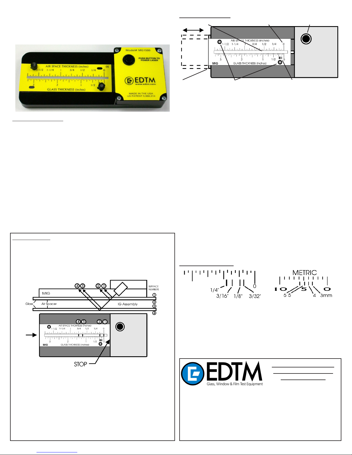
1. Laser Reection Region 2. “Zero Point” 3. Power Switch
4. Slide Assembly 5. Thumb Screws 6. ASTM Standards Indicator
DESCRIPTION OF PARTS
1. Laser Reection Region: When the laser is energized, the laser beams that reect
off the glass surfaces will appear in this laser reection region.
2. “Zero Point”: The zero point must be aligned with the rst laser reection prior to
taking glass thickness readings. All new units are shipped from the factory with the
zero point already aligned. If the zero point is out of alignment or if the operator is
changing scales, follow the instructions under “Zero Alignment”.
3. Power Switch: Prior to energizing the laser, be aware of your surroundings. The laser
will exit the gauge from the back side. DO NOT LOOK DIRECTLY INTO THE LASER
BEAM AND NEVER POINT THE LASER BEAM IN THE DIRECTION OF ANOTHER
PERSON. To turn on the laser, simply push and hold down the power button. The
laser will activate instantly.
4. Slide Assembly: The slide assembly holds the calibrated scale in place and allows
the operator to move the zero point left and right while taking readings. While taking
readings, the slide assembly starts in the fully inserted (against the stop) position.
After measuring the rst lite of glass, the entire slide assembly is slid to the left to
measure the air space and subsequent lites of glass.
5. Thumb Screws: The thumb screws are used to align the scale with the zero point as
well as to hold the scale in place. The thumb screws also provide a handy method of
grasping the slide in order to move it left and right. Two (2) spare thumb screws are
included in the carry case.
6. ASTM Standards Indicator: As you become more uent with the gauge, you will be-
gin to realize the benets of the ASTM standards indicator. ASTM standards dictate
the acceptable tolerances in the various glass thickness ranges. A table is printed on
page 3 of this operating manual for your reference. The four lines on the scale repre-
sent the thickness ranges of the four most common glass thicknesses used in North
America: 3/32”(SS), 1/8”(DS), 3/16”, and 1/4”. These designations are represented
on the scale respectively from right to left, as illustrated below. As you become more
uent in the operation of the gauge, you may be able to overlook the scale gradu-
ations and look directly at the ASTM range designations to expedite the measuring
process. PLEASE NOTE, the actual glass thickness you measure, can be less than
the traditional designations used by the ASTM standard range. For example, notice
that traditional 1/4” glass is actually closer to 7/32” in thickness.
ASTM Standards Indicator:
REFLECTION NUMBERS
© Copyright 2012 Electronic Design to Market, Inc. All rights reserved.1
GLASS THICKNESS & AIR SPACE MEASUREMENT: IG UNITS
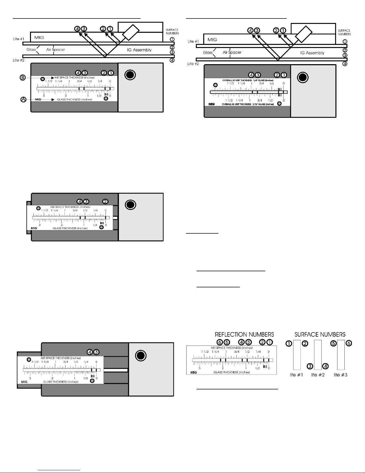
GLASS THICKNESS MEASUREMENT (LITE #1)
The bottom scale (Reference point “A”) is used for measuring the glass thickness while
the top scale (Reference point “B”) is used for measuring the air space. Please note
that the scales are different. DO NOT attempt to use the wrong scale for your measure-
ment. The best method of measurement is to work your way through the IG assembly.
In other words, measure the thickness of lite #1 rst, then read the air space, and nally
read the thickness of lite #2. To begin, verify that reection 1 is aligned with your “zero
point”. Reection 1 represents the top surface of the rst piece of glass, while reection
2 represents the bottom of the rst piece of glass. Once the zero point is aligned, you
can take your measurement. The distance between reection 1 and 2 is the thickness
of the rst lite of glass, as measured on the GLASS THICKNESS scale. The example
shows a glass thickness of approximately 7/32”. Regarding the ASTM standards indi-
cator, please note this falls into the acceptable range for 1/4” glass thickness.
AIR SPACE MEASUREMENT
To measure the air space, slide the entire slide assembly scale to the left and align reec-
tion 2 with the zero point. Once aligned, you can now measure the air space thickness
using the top scale. Reection 3 represents the top surface of the second lite of glass.
The distance between reection 2 and 3 represents the air space, as indicated on the
AIR SPACE THICKNESS scale. The example shows an air space of approximately 1/2
inch.
WARNING!
For the most accurate measurement of air space thickness, the operator should take
readings near the edge of the IG assembly. Be aware that many IG units may sag inward
or bow outward due to air pressure differences inside the window as opposed to the
outside atmospheric pressure. If a window deects inward or outward, the air space
thickness in the center of the IG unit will differ from the thickness near the edge. The
least amount of deection will occur near the edges of the glass near the spacer bar.
Please note, this is also a great method to check IG units for deection in production
as well as in the eld.
GLASS THICKNESS MEASUREMENT (LITE #2)
To measure the glass thickness of the second lite of glass, slide the entire slide assembly
to the left again, so that the “zero point” is lined up with reection 3. Reection 4 rep-
resents the bottom surface of the second lite of glass. The distance between reection
3 and 4 is the glass thickness of the second lite of glass. Be sure to use the “GLASS
THICKNESS” scale when measuring glass thickness.
OVERALL IG UNIT THICKNESS MEASUREMENT
To use the Overall IG Unit Thickness scales, the operator must rst verify the glass
thickness that is in the IG unit. To test this, the operator may use the glass and air
space thickness scale, or use the ASTM standards indicator which is located on both
the top and bottom of the Overall IG Unit Thickness scales. To use this, simply align the
zero point as described previously. Using the ASTM indicators, measure the thickness
of both lites of glass in the IG assembly. To use the overall thickness scales, both lites
of glass must be in the same thickness designation. In other words, if you have an IG
assembly with a 3/16” pane for lite 1 and a 1/4” pane for lite 2, you CAN NOT use this
scale. Both lites must be the same thickness.
To measure the overall IG unit thickness, align the zero point. Verify that the glass
thickness of the IG unit matches the scale you have installed on the gauge slide. Using
the correct thickness scale, measure the distance between reection 1 and reection
4. This is the overall IG unit thickness for the assembly being tested.
The example above illustrates an IG unit constructed of 1/4” lites of glass. The overall
thickness of the IG unit is 31/32”, as measured on the OVERALL IG UNIT THICKNESS
scale for 1/4” glass.
APPLICATIONS
This gauge has been successfully tested on a variety of glass combinations. The follow-
ing list includes the various types of glass that have been tested successfully: Single
pane oat glass, IG units (double, triple & quadruple glaze++), clear, Low-E, tempered,
reective, bronzed, tinted, laminated, bullet-proof, mirrors, plus others. The following
explanations dene the most common applications.
Single Pane Float Glass & IG Units
See “Glass Thickness & Air Space Measurement: IG units”.
Triple Glazed IG Units
Triple glazed IG units are measured in the same manner as the double
glazed IG units. The only difference will be two extra laser reections.
These two extra reections represent the third lite of glass. The distance
between reection 4 and 5 is the second air space (between lite 2 and lite
3), as measured on the Air Space Scale. The distance between reection 5
and 6 corresponds to the glass thickness of lite 3. Be sure to use the Glass
Thickness scale for this measurement.
Laminated Glass & Bullet Resistant Glass
Bullet resistant and laminated glass are measured in like manners. Use only
the Glass Thickness scale for these measurements. A faint laser reection
will occur at each laminate substrate. This allows you to measure the thick-
ness of each piece of glass in the laminated assembly, as well as the over-
all thickness of the laminated assembly. The distance between reection 1
and 2 is the thickness of pane 1. The distance between 2 and 3 is the thick-
ness of pane 2. The distance between 3 and 4 represents the thickness of
pane 3. The distance between reection 1 and 4 will yield the overall thick-
ness of the laminated assembly. All of these measurements use the Glass
Thickness Scale. The illustration shows two pieces of 1/4” glass laminated
on both sides of a 1/2” piece of glass. The overall thickness of the lami-
nated assembly is 1”. If the regular scale does not show the laminate inner-
layers, you can switch to the scale labeled “FOR LAMINATED OR BRIGHT
REFLECTION NUMBERS
REFLECTION NUMBERS
2
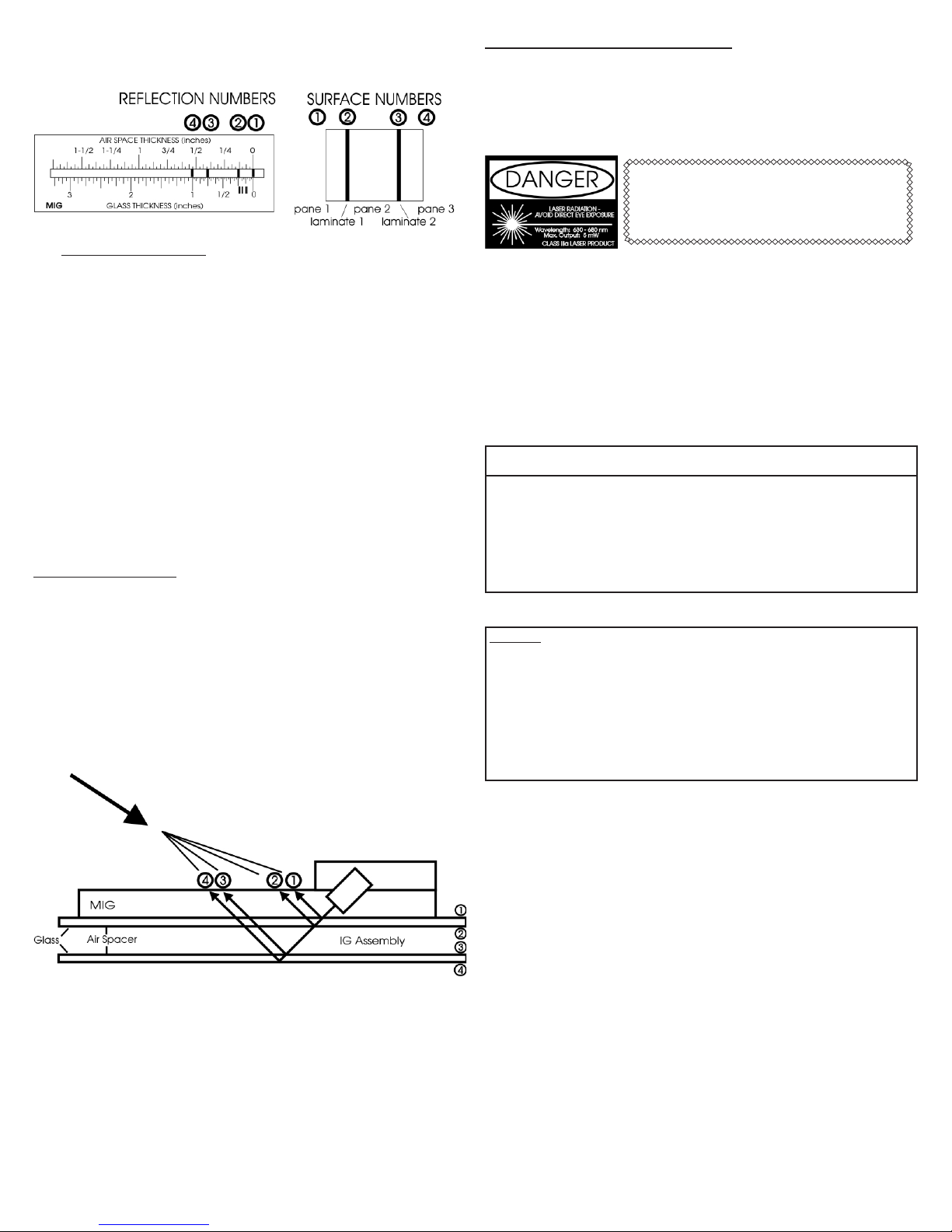
SUNLIGHT”. This scale is helpful for viewing the faint laminate inner-layer
reections. When using this scale, you will need to tilt your head at a 45
degree angle to view the reections.
Mirrors and Reective Glass
This gauge is capable of measuring mirror thickness as well as standard
reective glass used in the window industry. It is recommended that the user
test the gauge on various reective surfaces prior to use in the eld. This
will help the user to better understand the capabilities of the product.
For mirrors and single panes of reective glass, it is recommended that the
user take readings from the reective side of the glass. Readings from the
non-reective side will cause additional stray reections to occur, that may
appear confusing. Readings from the reective side will reduce the stray
reections and allow for easier glass thickness measurement. Due to the
intensity of the laser reection off the reective surface (surface 1), the sec-
ond reection (surface 2) will appear weaker than normal.
For insulating units containing reective glass, again it is recommended to
take measurements from the reective side of the IG unit. In other words,
place the gauge on the lite of glass that has the reective coating. It is pos-
sible to take readings on the side of the IG unit containing the non-reective
lite of glass, however additional stray reections may occur. Again, it is impor-
tant that the user test various reective surfaces to achieve a better under-
standing of the laser reections.
OPERATING CONDITIONS
FLATNESS: Prior to every reading, verify the gauge is resting atly against the glass
surface. Do not tilt the gauge or place any items under the gauge when taking read-
ings. Tilting the gauge in any way will adversely affect the accuracy of the readings.
BRIGHT LIGHT ENVIRONMENTS: This gauge will allow the operator to take measure-
ments in nearly all light conditions. If the operator is working in extreme bright light,
cupping your hand over the scale can help improve the contrast of the laser on the
scale. If shadowing the scale area does not work well enough, there is a scale that
is designed specically for bright light situations. Apply the scale that is labeled “FOR
LAMINATED OR BRIGHT SUNLIGHT”. With this scale in place, it will be necessary to
view the laser reections in the same plane as the reections. In other words, move
your head to view the reections at a 45 degree angle, as shown in the following il-
lustration. The laser reections should appear brighter with this scale.
SAFETY PRECAUTIONS AND MAINTENANCE
When not in use, the MIG and all scales should be kept in the carrying case for protec-
tion.
It is imperative that the bottom surface of the gauge is kept clean and free of any de-
bris. Any build-up on the bottom surface can cause the gauge to rock and/or not sit at
against the glass, causing incorrect readings. Therefore routinely inspect and clean
the bottom surface of the gauge.
This product emits a laser beam from the back side.
DO NOT point the laser at any ones eyes. ALWAYS
check the other side of the window being tested
to ensure that no one will be looking directly into
the laser.
On reective glass and mirrors, be aware that a signicant portion of the laser intensity
is reected back in the direction of the sliding scale. If the slide assembly is pulled out
signicantly, the scale and slide assembly will no longer block the reection of the laser
off the rst (reective) surface.
The MIG is powered by 2 AAA alkaline batteries. If the laser stops operating, replace
the batteries with alkalines. To access the batteries, remove the four screws located on
the top surface of the gauge. Do not touch the laser or any other items found inside the
cover. Replace the batteries and refasten the cover. Be sure to install the batteries cor-
rectly (polarity +/-). Installing the batteries backwards may cause permanent damage
to the laser and will not be covered by the product warranty.
DESIGNATION TOLERANCE
mm
2.5
3.0
4.0
5.0
5.5
6.0
8.0
10.0
inches
0.09
0.12
0.16
0.19
0.21
0.23
0.32
0.39
mm max.
2.57
3.40
4.19
5.05
5.54
6.20
8.43
10.31
mm min.
2.16
2.92
3.78
4.57
5.08
5.56
7.42
9.02
inches min.
0.085
0.115
0.149
0.180
0.200
0.219
0.292
0.355
inches max.
0.101
0.134
0.165
0.199
0.218
0.244
0.332
0.406
TRADITIONAL
DESIGNATION
3/32 in. (single)
1/8 in. (double)
5/32 in.
3/16 in.
7/32 in.
1/4 in.
5/16 in.
3/8 in.
AMERICAN SOCIETY FOR TESTING AND MATERIALS (ASTM)
Tolerance specications for at glass
WARRANTY
The manufacturer warrants all models of the MG1500 to be free from defects in material and workmanship
under normal use and service as specied within the operator’s manual. The manufacturer shall repair or
replace the unit within one (1) year from the original date of shipment after the unit is returned to the manu-
facturer’s factory, prepaid by the user, and the unit is disclosed to the manufacturer’s satisfaction, to be thus
defective. This warranty shall not apply to any unit that has been repaired or altered other than by the manu-
facturer. The aforementioned provisions do not extend the original warranty period of the unit which has been
repaired or replaced by the manufacturer. Batteries are not covered by warranty.
The manufacturer assumes no liability for the consequential damages of any kind through the use or misuse
of the MG1500 product by the purchaser or others. No other obligations or liabilities are expressed or implied.
All damage or liability claims will be limited to an amount equal to the sale price of the MG1500, as established
by the manufacturer.
3
Other EDTM Measuring Instrument manuals


