Nivetec Thermo Scientific AquaSensors AnalogPlus User manual
Thermo Scientific AquaSensors™
AnalogPlus™Dissolved Oxygen
Sensor
User Guide

Thermo Scientific AquaSensors™AnalogPlus™Dissolved Oxygen Sensor (ppm) User Guide 2
Safety Information
The Thermo Scientific AquaSensors AnalogPlus 1.0 inch Dissolved
Oxygen sensor shall be installed and operated only in the manner
specified. Only a skilled, trained or authorized person should carry out
installation, setup and operation of the sensor system.
Before using the sensor, make sure that the sensor cable is
connected as specified. Failure to do so may result in permanent
damage to the sensor or controller.
Protection against electric shock will be achieved only by observance
of the corresponding installation rules.

Thermo Scientific AquaSensors™AnalogPlus™Dissolved Oxygen Sensor (ppm) User Guide 3
TABLE OF CONTENTS
1. INTRODUCTION................................................................................................................................... 4
1.1. GENERAL INFORMATION.................................................................................................................... 4
1.2. INTENDED USE ................................................................................................................................... 5
2. PRODUCT DESCRIPTION.................................................................................................................. 6
2.1. SENSOR DESCRIPTION........................................................................................................................ 6
2.2. SENSOR CARE AND START-UP............................................................................................................ 7
3. INSTALLATION.................................................................................................................................... 9
3.1. WIRING.............................................................................................................................................. 9
3.2. SENSOR CONSTRUCTION .................................................................................................................. 10
3.3. SIDE WALL IMMERSION MOUNTING ................................................................................................ 11
3.4. IMMERSION MOUNT WITH HAND RAIL SWIVEL POSITIONING .......................................................... 12
3.5. IMMERSION MOUNT WITH BALL FLOAT........................................................................................... 14
3.6. PIPE TEE MOUNTING........................................................................................................................ 17
3.7. UNION MOUNTING........................................................................................................................... 19
4. DISSOLVED OXYGEN SENSOR MAINTENANCE...................................................................... 21
4.1. CLEANING THE DISSOLVED OXYGEN SENSOR HEAD ....................................................................... 21
4.2. D. O. SENSOR REFURBISHMENT -REPLACING THE MEMBRANE CAP AND ELECTROLYTE................ 22
4.3. DISSOLVED OXYGEN SENSOR TROUBLESHOOTING .......................................................................... 23
5. DISSOLVED OXYGEN PART NUMBERS...................................................................................... 24
5.1. D.O. SENSOR,AV88 UNIVERSAL ANALYZER AND MOUNTING HARDWARE OPTIONS ..................... 24
5.2. D.O. ELECTROLYTE AND MEMBRANE CAPS .................................................................................... 25
6. LIMITED WARRANTY...................................................................................................................... 26
7. TERMS AND CONDITIONS.............................................................................................................. 27
Thermo Scientific AquaSensors™AnalogPlus™Dissolved Oxygen Sensor (ppm) User Guide 4
1. INTRODUCTION
1.1. General Information
Thank you for purchasing the Thermo Scientific AquaSensors AnalogPlus Dissolved Oxygen Sensor. This
industrial sensor has many enhanced features that offer superior performance in process applications.
The product is designed for continuous use in industrial process applications and complies with safety
regulations currently in force. Improper use could lead to hazards for the user or a third-party, and/or adverse
effects to the plant or other equipment.
Thermo Fisher Scientific does not accept any liability for damage that may arise if information in this
manual is not followed. Therefore, the operating instructions and specifications must be read and
understood by all persons involved in installation and operation of this equipment.
This manual identifies safety instructions and additional information by means of the following symbols:
This symbol draws attention to safety instructions and warnings of potential danger,
which if neglected, could result in injury to persons and/or damage to property.
This symbol identifies additional information and instructions, which if neglected, could
lead to inefficient operation and possible loss of production.
It is recommended that this manual be made accessible to everyone who may need it as a reference.
Please contact Thermo Fisher Scientific or an authorized representative with any questions.
Thermo Scientific AquaSensors™AnalogPlus™Dissolved Oxygen Sensor (ppm) User Guide 5
1.2. Intended use
The Thermo Scientific AquaSensors AnalogPlus 1.0 inch Dissolved Oxygen sensor is designed to
continuously measure Dissolved Oxygen and temperature in aqueous solutions in accordance with the
technical product specifications in Section 2.2 of this manual.
Any other use, or use not mentioned here, that is incompatible with the technical specifications is deemed
inappropriate. The operator is solely responsible for any damage arising from such use.
Other prerequisites for appropriate use include:
• Observing the instructions, notes and requirements set out in this instruction manual.
• Observing all local safety regulations.
• Observing all warnings and cautions in the documentation regarding all products used in this
measurement system, including the Dissolved Oxygen sensor, mounting hardware, analyzer
electronics and cabling.
• Observing the prescribed environmental and operational conditions.
• Observing chemical compatibility with all wetted materials.
1.3. Safety Instructions
The AnalogPlus 1.0 inch Dissolved Oxygen sensor should be installed and operated
only by personnel familiar with the sensor and qualified for such work.
A defective sensor should be returned to Thermo Fisher Scientific for repair or
replacement. Contact Thermo Fisher Scientific to obtain a Return Material
Authorization (RMA) number.
No modifications to the AnalogPlus 1.0 inch Dissolved Oxygen sensor are allowed.
The manufacturer/supplier accepts no responsibility for damage caused by
unauthorized modifications. The risk is borne entirely by the user.
1.4. Removal from Service / Correct Disposal of the Sensor
Removal from Service
• Disconnect the cable wiring from the controller terminal block.
• Remove the sensor from the mounting hardware.
Correct Disposal of Unit
• When the sensor is taken out of service, observe the local environmental regulations for correct
disposal.
Thermo Scientific AquaSensors™AnalogPlus™Dissolved Oxygen Sensor (ppm) User Guide 6
2. PRODUCT DESCRIPTION
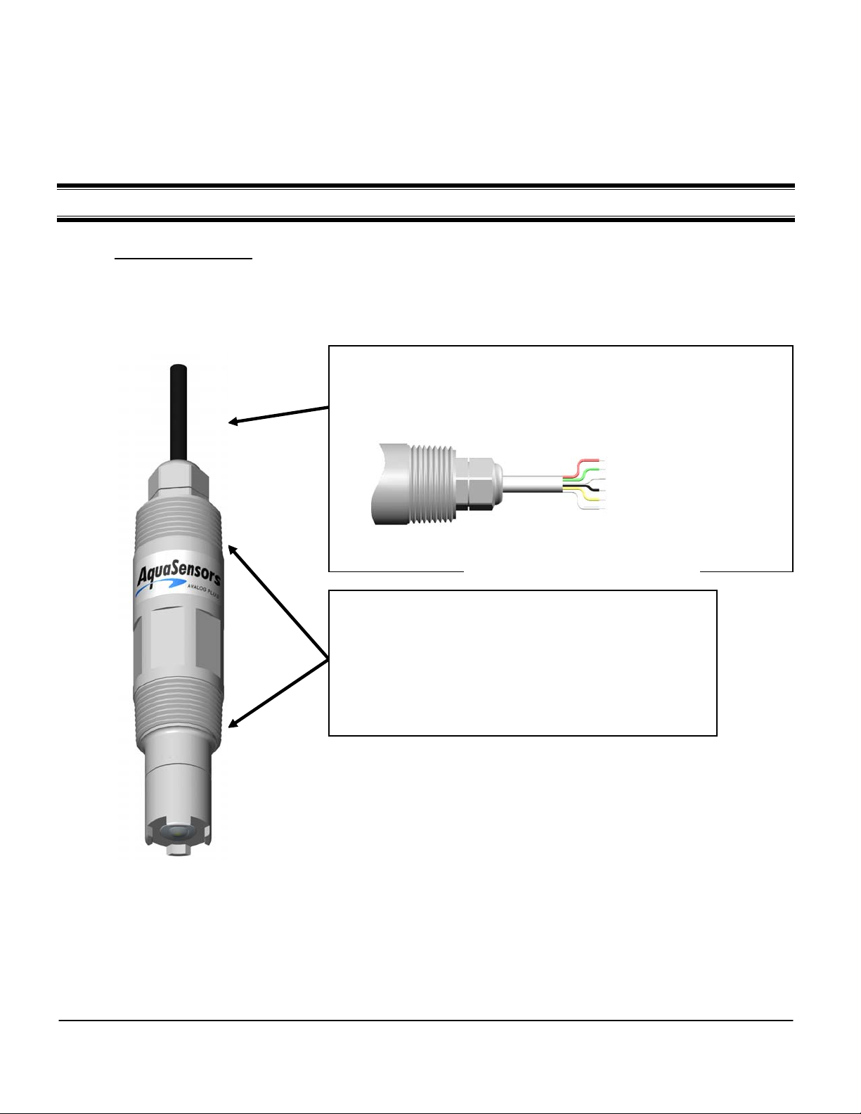
2.1. Sensor Description
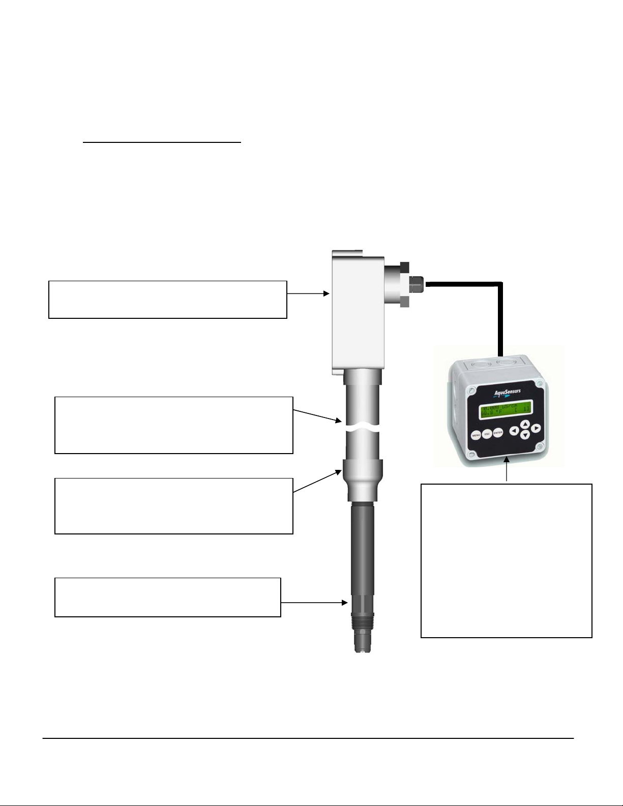
The Thermo Scientific AquaSensors 1- inch Dissolved Oxygen sensor uses the amperometric
measurement technique to maximize lifetime in continuous industrial applications. The sensor is easily
maintained and reconditioned by replacing the convenient membrane cap and electrolyte. The wires in the
sensor cable are color coded to allow for quick and easy installation into the AV88 Universal Analyzer.
Yellow Wire (Temperature)
Black Wire (Ground)
Red Wire (Sense)
Green Wire (Drive)
Blue Wire (+V)
White Wire (-V)
Drain/Shield (Earth)
The wires in the sensor cable are color coded to match the
terminal strip connection within the AV88 Universal
Analyzer Controller.
Figure 2.2: D.O. sensor hook-up
The sensor body has 1 inch NPT threads for the following
mounting options:
¾ Pipe tee assembly
¾ Immersion mount assembly
¾ Union mount assembly
Figure 2.1: 1.0 inch D.O. Sensor

Thermo Scientific AquaSensors™AnalogPlus™Dissolved Oxygen Sensor (ppm) User Guide 7
2.2. Sensor Care and Start-up
Working with the Protective Cap
The sensor is shipped with a protective cap on the sensor head to keep the membrane wet and to protect the
membrane from damage. The cap should remain on the sensor head until the sensor is installed in liquid
process. It is important to note that the cap should be pulled straight off by inserting a fingernail between the
cap and the sensor body and walking the cap down until it comes off. Be careful not to touch the membrane.
Working with the Membrane Cap
The membrane cap is screwed on and care should be taken not to unscrew it. The cap contains dissolved
oxygen electrolyte that will spill out if the cap is removed.
Power the Sensor Prior to Calibration
The sensor has been charged and tested prior to shipment. After installation, leave the sensor powered for at
least 4 hours in the process prior to calibration. The AV88 analyzer supports both 1-point sample calibration
and air calibration.
The 1-point sample calibration should be done with a measured DO reading that is as high up the scale as
possible, ideally 8 or 9 ppm. With this calibration the current sensor reading can be set to a known value.
With the Air calibration, the sensor is held in air and with atmospheric pressure correctly configured, will
calibrate to a calculated value of oxygen in the air. If there is a large temperature difference between the
water and the air it may be necessary to wait for up to 5 minutes before the temperature of the sensor body
comes to a new steady state.
Temperature can also be calibrated with a sample calibration and it may be advantageous to calibrate the
temperature of the sensor prior to calibration of dissolved oxygen since the D.O. reading is compensated by
temperature.
Take care to protect the sensor membrane from impact and be sure to keep the membrane cap tight.
Membrane material covers
electrodes and should be
protected from impact.
Membrane Cap tightens when turning it
clockwise. Keep it tight.

Thermo Scientific AquaSensors™AnalogPlus™Dissolved Oxygen Sensor (ppm) User Guide 8
Specifications
Wetted Materials……………………………. Sensor Body – PEEK®
Membrane – FEP
O-Ring Seals - Viton®
(Consult factory for customized material construction)
Operating Temperature…………………….. 23°F to 122°F (-5°C to 50°C)
Maximum Pressure…………………………. 100 psi @ 50°F
Max Operating Pressure…………………… 20 psi @ 50°F
Maximum Flow Rate………………………... 10 ft/sec (3 m/sec)
Measuring Range…………………………… 0 to 40 ppm
Resolution……………………………………. 0.01 ppm
Standard Sensor Cable Length……………. 10 ft (3 m)
Cable Wire Colors…………………………... Yellow Wire (Temperature)
Black Wire (Ground)
Red Wire (Sense)
Green Wire (Drive)
Blue Wire (+V)
White Wire (-V)
Drain/Shield (Earth)
Maximum Transmission Distance…………. 300 ft (914 m)
The sensor will arrive with a protective cap that keeps the sensor membrane hydrated.
For short-term storage, put several drops of Thermo Scientific AquaSensors D.O. electrolyte (P/N
RDOK1) on the absorbent material in the protective cap and replace the cap on the sensor. This
keeps the membrane moist.
For extended storage, repeat the above short-term storage procedure every 2 to 4 weeks,
depending on the surrounding environmental conditions.
Make sure all wetted materials are compatible with process chemicals at operating temperatures
and pressures.

Thermo Scientific AquaSensors™AnalogPlus™Dissolved Oxygen Sensor (ppm) User Guide 9
3. INSTALLATION
3.1. Wiring
Yellow Wire (Temperature)
Black Wire (Ground)
Red Wire (Sense)
Green Wire (Drive)
Blue Wire (+V)
White Wire (-V)
Drain/Shield (Earth)
Figure 3.1: D.O. Sensor Hook-Up
There are two different methods for electrical connection between the sensor and the Dissolved Oxygen
Analyzer - either direct or through a junction box.
3.1.1. Direct Connection
1. Insert the sensor cable through a watertight cord grip into the AV88 Universal Analyzer. Conduit holes
are found on the bottom of the analyzer for this purpose.
2. Connect the sensor wires to the AV88 as shown on the AV88 wiring chart.
3.1.2. Indirect Connection (Using a Junction Box)
1. Insert the sensor cable and the interconnect cable through a watertight cord grip into the junction box
that has a terminal strip designed to make the proper connections.
2. Connect both the sensor cable wires and the interconnect wires to the terminal strip.
3. Insert the interconnect cable through a watertight cord grip into the AV88F Analyzer.
Conduit holes are found on the bottom of the analyzer for this purpose.
4. Connect the sensor wires to the AV88 as outlined in the analyzer manual.
Be sure that the wire colors of the sensor cable match those of the interconnect cable on
either side of the terminal strip.
Route the interconnect cable through metal conduit to minimize electrical noise that may
interfere with the sensor signal.

Thermo Scientific AquaSensors™AnalogPlus™Dissolved Oxygen Sensor (ppm) User Guide 10
3.2. Sensor Construction
The AnalogPlus Dissolved Oxygen sensor has 1-inch NPT threads on the front and back of the
sensor body for easy installation in tee, union mount and immersion mount hardware.
Save the protective cap and use it to
keep membrane moist whenever the
sensor is removed from service.
If the sensor does not calibrate, refer
to Section 4 to review maintenance,
refurbishment and troubleshooting
options.
The sensor should be positioned at
least 15°up from horizontal. This
will insure that entrained air does not
form a pocket around the sensor
head.
Dimensions: IN (mm)
DO NOT USE PIPE SEALANT.
Pipe sealants may not provide
adequate sealing or may react with
different plastic materials. Use
thread tape.
DO NOT OVER TIGHTEN!
Maximum torque: 65 lbs⋅inch (7 N⋅m)
Figure 3.2: 1 Inch Sensor Body
Thermo Scientific AquaSensors™AnalogPlus™Dissolved Oxygen Sensor (ppm) User Guide 11
3.3. Side Wall Immersion Mounting
Standard immersion mounting hardware is used to rigidly mount a sensor on the sidewall of a vessel. It is
usually secured with U-bolts (customer supplied). The mounting assembly consists of a seven-foot pole with
an integral junction box. Different pole lengths can be configured on request. To remove the sensor, the
hardware must be lifted out of the tank and laid down on the walkway. The pole protects the sensor cable
from damage.
Junction Box for sensor and extension cable
wiring to AV88 Universal Analyzer.
Standard 7 foot PVC pipe extension to place
sensor into tank. Pipe protects sensor cable from
damage.
Adapter to connect the sensor to the extension
pipe. This may or may not be needed depending
on the type of sensor.
AnalogPlus sensors are threaded on to the 1-
inch NPT thread adapter.
AV88 Universal Analyzer connects
to any AnalogPlus sensor.
Relays can be used for sensor
head wash control hardware.
Two current outputs can be used
for reporting dissolved oxygen and
temperature data.
Figure 3.3: Immersion Mount Illustration

Thermo Scientific AquaSensors™AnalogPlus™Dissolved Oxygen Sensor (ppm) User Guide 12
3.4. Immersion Mount with Hand Rail Swivel Positioning
Standard immersion mounting hardware with handrail swivel positioning is used to rigidly mount a sensor
away from the sidewall of a vessel near the surface of the water. The sensor should be positioned in such a
way that the sensor head is angled away from water flow (not into it). When the sensor is positioned in the
tank the pivot and swivel features are locked into place, insuring that the sensor position will remain fixed in
the tank. Different pole lengths can be configured on request or easily modified on site.
To remove the sensor, the swivel is unlocked and the pole swings up as shown in the illustration on the next
page. The pole protects the sensor cable from damage. The junction box is used to connect the sensor cable
in the pipe and to take an extension cable to the AV88 analyzer. When automatic cleaning of the sensor is
needed an AV88 universal analyzer relay can be configured to activate a solenoid valve to release air or water
on the sensor head.
Water Flow
Figure 3.4: Immersion Mount Hardware with Hand Rail Swivel Positioning – In measurement position.

Thermo Scientific AquaSensors™AnalogPlus™Dissolved Oxygen Sensor (ppm) User Guide 13
The swivel hardware makes it easy to access the sensor head for service, cleaning and calibration as
shown below.
Figure 3.5: Immersion Mount Hardware with Hand Rail Swivel Positioning - Retracted

Thermo Scientific AquaSensors™AnalogPlus™Dissolved Oxygen Sensor (ppm) User Guide 14
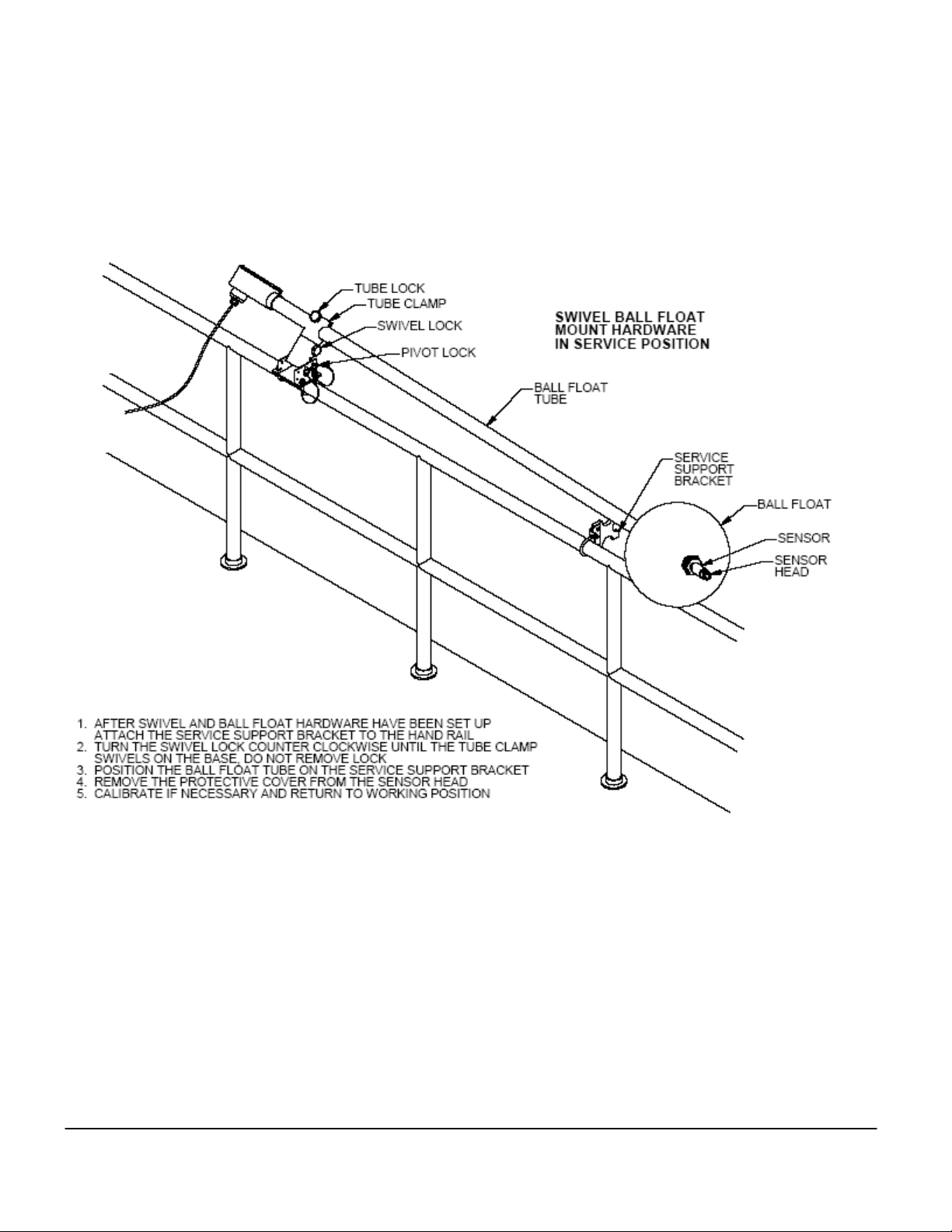
3.5. Immersion Mount with Ball Float
Standard immersion mounting hardware with a ball float is used to position a sensor at a fixed level below the
surface of the water. The swivel hardware is left unlocked so that it can move up or down as the level of the
water changes. The ball float is inflated with air. There is a 45-degree angle at the end of the extension pipe
to maintain the proper positioning of the float in the water.
To remove the sensor, the swivel is unlocked and the pole swings up as shown in the illustration on the next
page. The pole protects the sensor cable from damage. The junction box is used to connect the sensor cable
in the pipe and to take an extension cable to the AV88 analyzer. When automatic cleaning of the sensor is
needed an AV88 universal analyzer relay can be configured to activate a solenoid valve to release air or water
on the sensor head.
Figure 3.6: Immersion Mount Hardware with Ball Float – In measurement position.
Thermo Scientific AquaSensors™AnalogPlus™Dissolved Oxygen Sensor (ppm) User Guide 15
The swivel hardware makes it easy to access the sensor head and the ball float for service, cleaning and
calibration as shown below.
Figure 3.7: Immersion Mount Hardware with Ball Float – Retracted.

Thermo Scientific AquaSensors™AnalogPlus™Dissolved Oxygen Sensor (ppm) User Guide 16
Detailed Insertion Mount Installation Instructions
1. Wiring:
a. Route the sensor cable through the 1.5 inch extension pipe.
b. Apply Teflon® tape to the sensor threads.
c. Attach the sensor to the 1.0 inch NPT reducing coupling by turning the sensor in a
clockwise direction until secure.
d. Either route the cable directly to the AV88 analyzer or splice the wires in a junction
box and use an extension cable.
e. Insert the cable into the AV88 analyzer through a watertight cord grip. Conduit
holes are provided for the cord grip on the bottom of the AV88 Analyzer.
f. Connect the sensor wires into the AV88 sensor terminal block as shown in the
AV88 manual.
2. Calibrate:
a. Power the AV88 Analyzer and let the sensor run for at least 1 hour before
calibration.
b. Remove the protective cap from the sensor head and make sure moisture is
present and the membrane has not dried out. If the protective cap is dry, the
sensor should be hydrated in tap water for at least 1 hour prior to calibration.
c. Calibrate the Dissolved Oxygen sensor as explained in the AV88 manual.
Subsequent calibrations should be scheduled based on process demands.
d. If measurement response time is slow or if the sensor will not calibrate, refer to
Section 4 for maintenance, refurbishment and troubleshooting suggestions.
3. Mount: Secure the pipe assembly so that the sensor is fully immersed in the process
a. Side Wall Immersion Mounting: Use 2 inch U-bolts to secure the extension pipe to
the side wall.
b. Immersion Mount with had rail swivel positioning: Refer to illustration notes on
pages 12 and 13 for hand rail mounting and positioning.
c. Immersion Mount with ball float: Refer to illustration notes on pages 14 and 15 for
hand rail and ball float mounting and positioning.
Be sure that the wire colors of the sensor cable match those of the
interconnect cable on either side of the terminal strip.
Do not route the interconnect cable conduit where there are AC or DC
power cables which create electrical noise that may interfere with the
sensor signal.
Route the interconnect cable through metal conduit to minimize electrical
noise that may interfere with the sensor signal.

Thermo Scientific AquaSensors™AnalogPlus™Dissolved Oxygen Sensor (ppm) User Guide 17
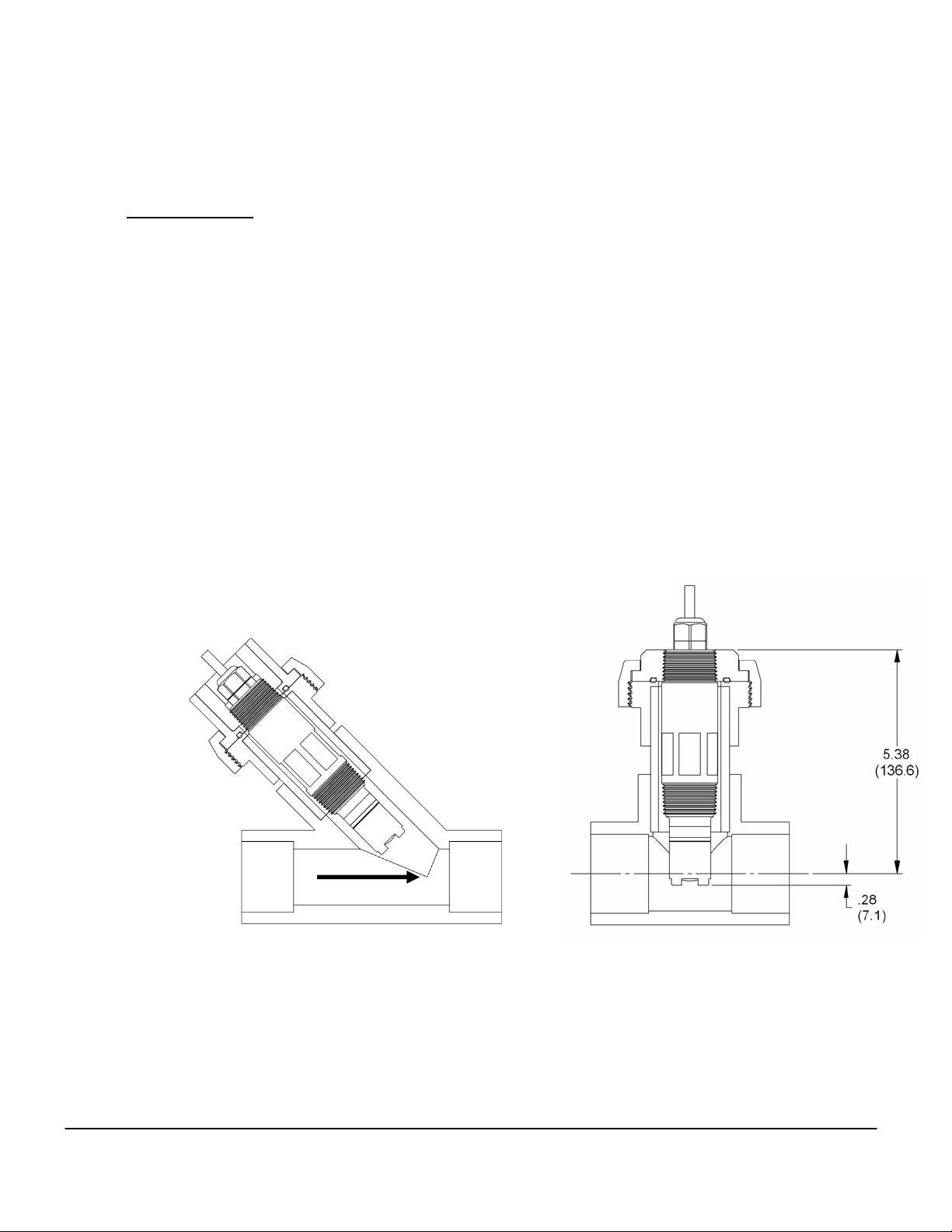
3.6. Pipe Tee Mounting
Normally available pipe tees vary widely in construction dimensions. CPVC pipe tees are most
generally available with schedule 80 walls. Stainless steel tees have thinner walls that change
the final position of the sensor. Common mounting with a CPVC pipe tee is shown.
Dimensions: IN (mm)
Figure 3.8: Schedule 80 PVC Tee

Thermo Scientific AquaSensors™AnalogPlus™Dissolved Oxygen Sensor (ppm) User Guide 18
Detailed Pipe Tee Installation Instructions
1. Wiring:
a. Route the cable either through conduit or on a cable tray.
b. Insert the sensor cable into the AV88 Universal Analyzer through a watertight cord
grip. Conduit holes are provided for the cord grip on the bottom of the AV88
Universal Analyzer.
c. Connect the sensor wires into the AV88 sensor terminal block as shown in the
AV88 manual.
2. Calibrate:
a. Power the AV88 Analyzer and let the sensor run for at least 1 hour before
calibration.
b. Remove the protective cap from the sensor head and make sure moisture is
present and the membrane has not dried out. If the protective cap is dry, the
sensor should be hydrated in tap water for at least 1 hour prior to calibration.
c. Calibrate the Dissolved Oxygen sensor as explained in the AV88 manual.
Subsequent calibrations should be scheduled based on process demands.
d. If measurement response time is slow or if the sensor will not calibrate, refer to
Section 4 for maintenance, refurbishment and troubleshooting suggestions.
3. Mount:
a. Apply Teflon®tape to the sensor body threads.
b. Insert the sensor into the tee and slowly turn clockwise until secure. Tighten the
sensor with a wrench until snug to prevent leaking. Be sure the pipe remains full
after the sensor is installed.
Thermo Scientific AquaSensors™AnalogPlus™Dissolved Oxygen Sensor (ppm) User Guide 19
3.7. Union Mounting
Union mount hardware makes it easy to remove and insert the sensor for applications where
calibration and/or cleaning is frequent. In pipe installations a ‘Y’ configuration is recommended to
reduce the impact of particulate matter on the sensor head and improve sensor life. Union Mounting
in a ‘T’ configuration is also available.
Union Mount Advantages
9 Optimal positioning of sensing
surface.
9 Trouble-free installation.
9 Quick disconnect.
9 No cable twisting during installation
or removal.
9 Easy maintenance.
Water Flow
Union Hardware in T Configuration
Part Number: MH1042
Union Hardware in Y Configuration
to reduce wear on sensor head.
Part Number: MH1042-Y
Dimensions: IN
(
mm
)
Figure 3.9: Union Mounting Options

Thermo Scientific AquaSensors™AnalogPlus™Dissolved Oxygen Sensor (ppm) User Guide 20
Detailed Union Mount Installation Instructions
1. Wiring:
a. Apply Teflon® tape to the rear sensor body threads and pass the cable through
the adapter. Thread the adapter onto the sensor clockwise until it is secure.
b. Pass the union collar over the cable and onto the adapter with the threads facing
the sensor.
c. Route the cable either through conduit or on a cable tray.
d. Insert the sensor cable into the AV88 through a watertight cord grip. Conduit
holes are provided for the cord grip on the bottom of the AV88 Analyzer.
e. Connect the sensor wires into the AV88 sensor terminal block as shown in the
AV88 manual.
2. Calibrate:
a. Power the AV88 Analyzer and let the sensor run for at least 1 hour before
calibration.
b. Remove the protective cap from the sensor head and make sure moisture is
present and the membrane has not dried out. If the protective cap is dry, the
sensor should be hydrated in tap water for at least 1 hour prior to calibration.
c. Calibrate the Dissolved Oxygen sensor as explained in the AV88 manual.
Subsequent calibrations should be scheduled based on process demands.
d. If measurement response time is slow or if the sensor will not calibrate, refer to
Section 4 for maintenance, refurbishment and troubleshooting suggestions.
3. Mount:
a. Assemble the lower portion of the mounting hardware by threading the pipe nipple
into the threaded flange and the tee. Apply Teflon® tape to the threads.
b. Inspect the O-ring on the union-mounting threaded flange for imperfections or
particles of dirt that may prevent the O-ring seal from seating properly.
c. Carefully insert the sensor into the Thermo Scientific AquaSensors union-
mounting tee. Turning the retaining collar clockwise and hand tighten until snug.
Be sure the pipe remains full when the sensor is installed.
Table of contents
Other Nivetec Accessories manuals


Popular Accessories manuals by other brands

VOLTCRAFT
VOLTCRAFT 2588045 operating instructions

GFL
GFL 3031 operating instructions

Ningbo Wonder Power Tech
Ningbo Wonder Power Tech SK-B2 user guide

Smanos
Smanos DS2300 user manual

Hewlett Packard Enterprise
Hewlett Packard Enterprise Aruba User Experience Insight quick start guide

ekwb
ekwb EK-FB ASUS Maximus XI HERO installation manual


