Nivetec Signet 2000 Series User manual

Signet 2000 Micro Flow Sensor
*3-2000.090-1*
3-2000.090-1 Rev. 6 01/19
Operating Instructions
Description
Features
The Signet 2000 Micro Flow Rotor Sensor is constructed of Polyphenylene Sulfide (PPS)
which provides high material strength. The 2000 offers two flow ranges starting at 0.11 or
1.13 lpm (0.03 or 0.3 gpm), for clean process liquids, regardless of fluid color or opacity.
This sensor can be connected to flexible tubing or rigid pipe, and uses standard hardware
for mounting. Only one moving part and a low pressure drop across the sensor reduces
operating costs and maintenance requirements.
• Operating range 0.11 to 12.11 lpm (0.03 to 3.2 U.S. gpm)
• Simple mounting
• ¼ in. NPT or ISO threads for simple pipe or tubing connection
• Measures opaque and transparent liquids
• Low pressure drop
• Standard cable 7.6 m (25 ft)
Warranty Statement................................................................................ 2
Product Registration............................................................................... 2
Chemical Compatibility........................................................................... 2
Safety Information .................................................................................. 2
Dimensions............................................................................................. 2
Specifications ......................................................................................... 3
Compatible Instrument Wiring ................................................................ 3
Recommended Sensor Position............................................................. 3
Sensor Mount Instructions...................................................................... 4
Fittings Installation.................................................................................. 4
K-Factors................................................................................................ 4
Ordering Information............................................................................... 4
Table of Contents
• English
• Deutsch
• Français
• 中文
2Signet 2000 Micro Flow Sensor
Warning / Caution / Danger
Indicates a potential hazard. Failure to follow all warnings
may lead to equipment damage, injury, or death
Personal Protective Equipment (PPE)
Always utilize the most appropriate PPE during
installation and service of Signet products.
Pressurized System Warning
Sensor may be under pressure, take caution to vent
system prior to installation or removal. Failure to do so
may result in equipment damage and/or serious injury.
Note / Technical Notes
Highlights additional information or detailed procedure.
Warranty Information
Safety Information
Product Registration
Thank you for purchasing the Signet line of Georg Fischer
measurement products.
If you would like to register your product(s), you can now
register online in one of the following ways:
• Visit our website www.gfsignet.com and
click on Product Registration Form
• If this is a pdf manual (digital copy), click here
Refer to your local Georg Fischer Sales office for the most
current warranty statement.
All warranty and non-warranty repairs being returned must
include a fully completed Service Form and goods must be
returned to your local GF Sales office or distributor.
Product returned without a Service Form may not be
warranty replaced or repaired.
Signet products with limited shelf-life (e.g. pH, ORP, chlorine
electrodes, calibration solutions; e.g. pH buffers, turbidity
standards or other solutions) are warranted out of box but not
warranted against any damage, due to process or application
failures (e.g. high temperature,
chemical poisoning, dry-out) or
mishandling (e.g. broken glass,
damaged membrane, freezing
and/or extreme temperatures).
1. Depressurize and vent system prior to installation/removal.
2. Confirm chemical compatibility before use.
3. Do not exceed maximum temperature/pressure
specifications.
4. Wear safety goggles or faceshield during installation/
service.
5. Do not alter product construction.
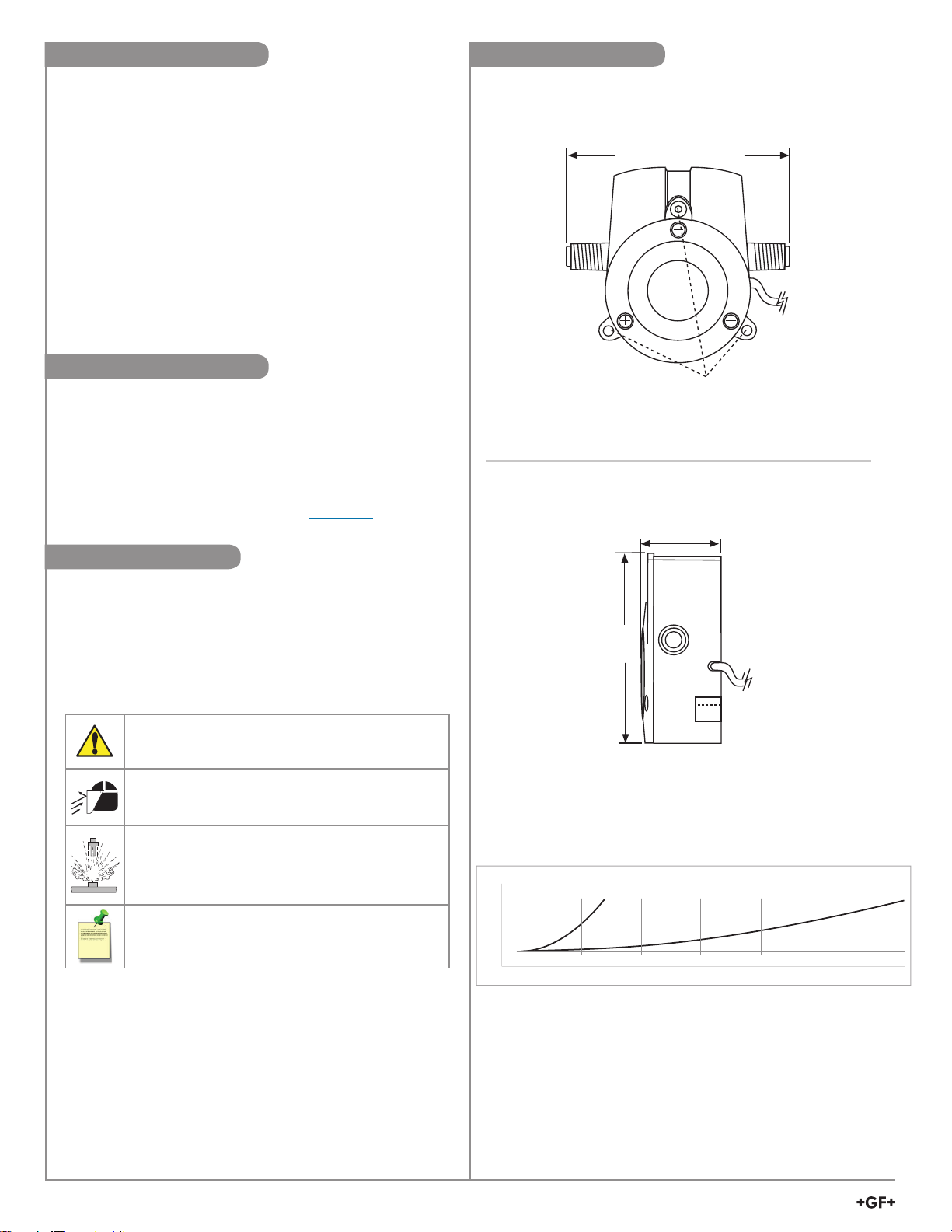
Dimensions
100 mm (3.94 in.)
Mounting tabs for metric M3 or
standard #6 screws on 68 mm
(2.68 in.) bolt circle
Top View
bar
1.7
1.4
1.0
0.7
0.3
0
psi
25
20
15
10
5
0
0 0.5 1 1.5 2 2.5 3
0 1.9 3.8 5.7 7.6 9.5 11.4
gpm
lpm
Pressure Drop Across Sensor vs. Flow Rate
3-2000-1X 3-2000-2X
36 mm (1.42 in.)
81 mm
(3.2 in.)
Side View

3
Signet 2000 Micro Flow Sensor
Recommended Sensor Position
Compatible Instrument WiringSpecifications
General
Flow Range:
-11 & -12 version............0.11 to 2.6 lpm (0.03 to 0.7 gpm)
-21 & -22 version............1.13 to 12.11 lpm (0.3 to 3.2 gpm)
Linearity.............................±1.2% of full range
Repeatability......................±0.5% of full range
Connections.......................1/4 in. NPT (male) or
ISO 7/1 - R1/4 (male)
Wetted Materials
Sensor Body and Cover ....40% glass filled Polyphenylene
Sulfide
Rotor..................................PEEK®, natural, unfilled
Cover O-ring......................
FKM
Electrical
Power ................................5 to 24 VDC ±10%, regulated,
10 mA max.
Output type: Open-collector, sinking, 10 mA
max.
Cable Length .....................7.6 m (25 ft), can be extended up
to 300 m (1000 ft)
Cable Type ........................2-conductor twisted pair w/shield
(Belden 8451)
Max. Pressure/Temperature Ratings
0 °C to 80 °C (32 °F to 176 °F) @ 5.5 bar (80 psi) max
Shipping Weight
250 g (9.6 oz)
Standards and Approvals
• Manufactured under ISO 9001 for Quality and ISO 14001
for Environmental Management and OHSAS 18001 for
Occupational Health and Safety
PEEK®is a registered trademark of Victrex plc.
Technical Notes:
• Use 2-conductor twisted-pair shielded cable for
sensor cable splices up to 300 m (1000 ft) max.
• Maintain cable shield through cable splice.
• Route sensor cable away from AC power lines.
• AUX power required when used with any Signet
8550 Process Pro Flow Transmitter.
Signet 2000
Input
Gnd.
10 kΩ
+5 to 24
VDC
-
Black
Shield
Red
Other
Instrument
Black (5 to 24 VDC)
Red (Signal out)
Shield (DC return)
Blk
Power
Red
Freq. input
Shld
Gnd
Other
Instrument
Signet
Instrument
Technical Notes:
• Horizontal surface mount (±30°) recommended for
optimum performance.
• Suitable for clean fluids only. Suspended solids will
cause mechanical failure.
• 1/4 in. NPT or ISO 7/1 - R1/4 (male) port connections
• NEMA 4X/IP65 splashproof enclosure.
0°
30°30°
Recommended
mounting angles
Vertical mounting
not recommended

3-2000.090 Rev. 6 01/19 English
Mfr. Part No. Code Description
3-2000-11 198 822 000 Micro Flow Sensor, low w/0.25 in. NPT
3-2000-12 198 822 001 Micro Flow Sensor, low w/ISO 7/1-R1/4
3-2000-21 198 822 002 Micro Flow Sensor, high w/0.25 in. NPT
3-2000-22 198 822 003 Micro Flow Sensor, high w/ISO 7/1-R1/4
Accessories
Mfr. Part No. Code Description
3-2000.390 198 820 050 Replacement rotor kit
1220-0029 198 820 049 Cover O-ring
2450-0620 198 820 051 Cover screw
5523-0222 159 000 392 Cable (per foot), 2 cond. w/shield, 22 AWG
Ordering Information
CAUTION:
• Maximum pipe fitting torque: 13 Nm (10 lb)
• DO NOT overtighten. Failure to observe torque specification may
permanently damage sensor ports.
The K-Factors listed below represent
the number of pulses the sensor will
generate for each engineering unit of
fluid which passes. They are listed in
U.S. gallons, liters and ml by sensor
model:
Conversion Formulas:
1 U.S. gallon =
0.83267 Imperial gallon
Technical Notes:
• Compatible fittings (customer
supplied): Female union
(shown), reducer, or hose
barb type.
• Always apply thread sealant
to sensor port threads to
prevent leakage.
Sealant
2000 Pipe fitting Pipe
Pipe fittingPipe
1
Mounting surface
2Remove sensor then use correct
screws for panel material.
Mounting surface (top),
68 mm (2.68 in.) bolt circle
120°
#6 or M3 metric
screws recommended
Mounting surface (side)
K-FACTORS
Sensor
Model
Pulses per
U.S. GAL
Pulses per
Liter Pulses per ml
3-2000-11 9950 2629 2.629
3-2000-12 9950 2629 2.629
3-2000-21 3160 834.9 0.835
3-2000-22 3160 834.9 0.835
Sensor Mount Instructions
Fitting Installation
K-Factors
This manual suits for next models
4
Table of contents
Other Nivetec Accessories manuals


