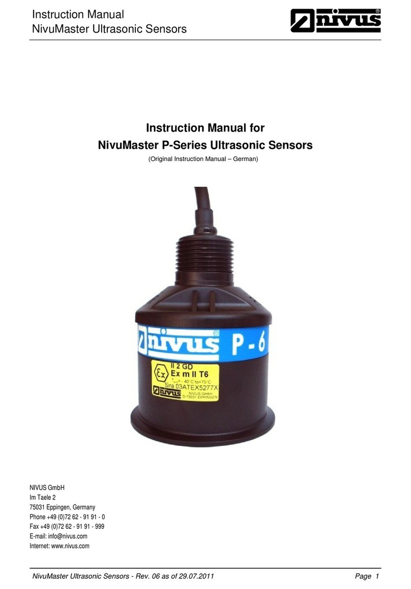
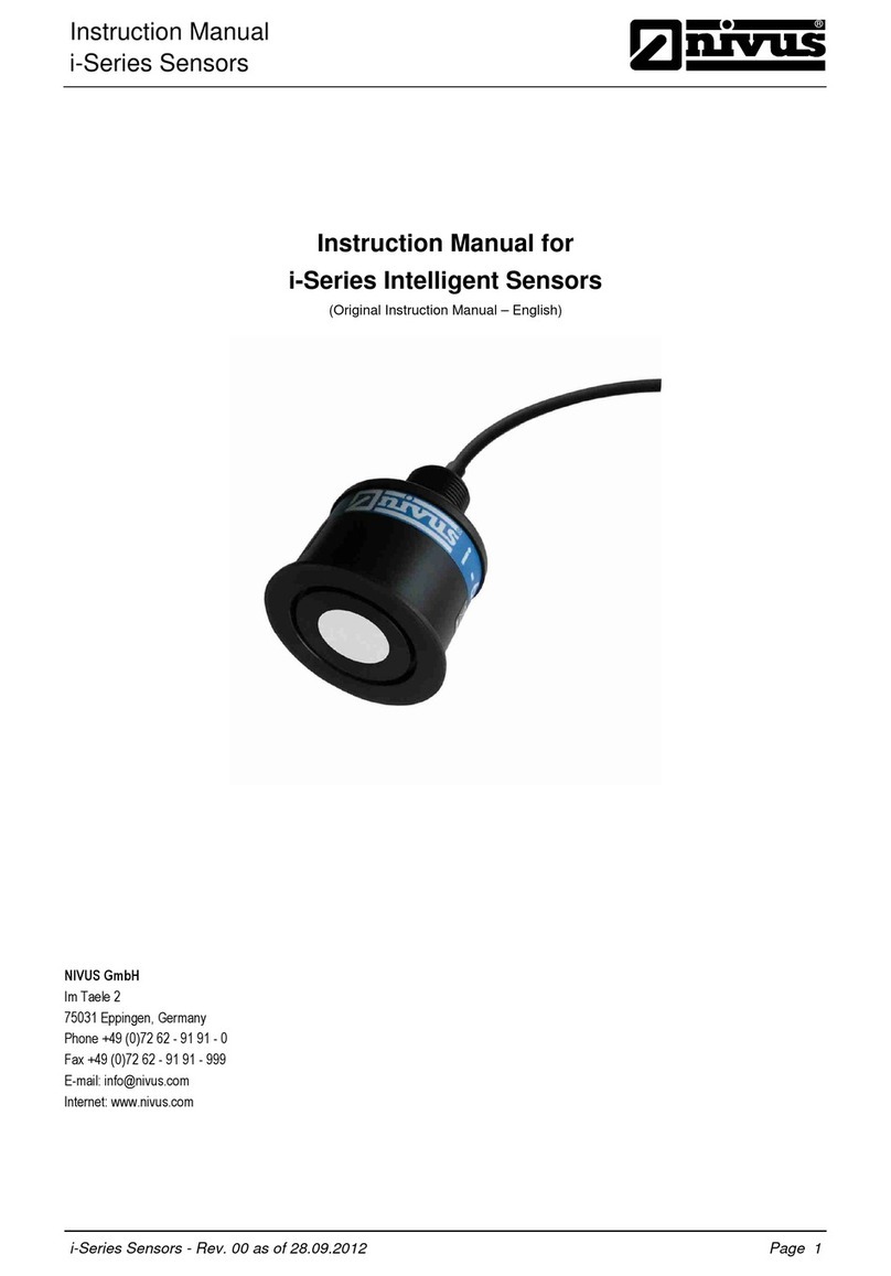
Nivus CSM Series Owner's manual

Technical Instructions for
Correlation Sensors
®
Correlation Sensors – Rev. 07 as of 20.04.2016 Page 1
Technical Instructions for
Correlation Sensors and external Electronic Box
(Original technical instructions – German)
as of Firmware Version:
1.58 (POA
-V2)
1.59 (OCL
-L1)
1.58
(CS2)
1.
64 (EBM)
NIVUS GmbH
Im Taele 2
75031 Eppingen, Germany
Phone: +49 (0) 72 62 / 91 91 - 0
Fax: +49 (0) 72 62 / 91 91 - 999
Internet: www.nivus.com

Branch offices
page 2
®
NIVUS AG
Hauptstrasse 49
8750 Glarus, Switzerland
Phone: +41 (0)55 6452066
Fax: +41 (0)55 6452014
E-mail: swiss@nivus.com
Internet: www.nivus.de
NIVUS Austria
Mühlbergstraße 33B
3382 Loosdorf, Austria
Phone: +43 (2754) 567 63 21
Fax: +43 (2754) 567 63 20
Internet: www.nivus.de
NIVUS France
14, rue de la Paix
67770 Sessenheim, France
Phone: +33 (0)3 88071696
Fax: +33 (0)3 88071697
E-mail: info@nivus.fr
Internet: www.nivus.fr
NIVUS U.K. Ltd
Wedgewood Rugby Road
Weston under Wetherley
Royal Leamington Spa
CV33 9BW, Warwickshire
Phone: +44 (0)1926 632470
Internet: www.nivus.com
NIVUS U.K.
1 Arisaig Close
Eaglescliffe
Stockton on Tees
Cleveland, TS16 9EY
Phone: +44 (0)1642 659294
Internet: www.nivus.com
NIVUS Sp. z o.o.
ul. Hutnicza 3 / B-18
81-212 Gdynia, Poland
Phone: +48 (0) 58 7602015
Fax: +48 (0) 58 7602014
Internet: www.nivus.pl
NIVUS Middle East (FZE)
Building Q 1-1 ap. 055
P.O. Box: 9217
Sharjah Airport International
Free Zone
Phone: +971 6 55 78 224
Fax: +971 6 55 78 225
E-mail: Middle-East@nivus.com
Internet: www.nivus.com
NIVUS Korea Co. Ltd.
#2502 M Dong, Technopark IT Center,
32 Song-do-gwa-hak-ro,
Yeon-su-gu, INCHEON, Korea 406-840,
Phone: +82 32 209 8588
Fax: +82 32 209 8590
E-Mail: [email protected]
Internet: www.nivuskorea.com
NIVUS Vietnam
21 Pho Duc Chinh, Ba Dinh,
Hanoi, Vietnam
Mobile (VN) 012 0446 7724
E-Mail: vietnam@nivus.com

Technical Instructions for
Correlation Sensors
®
Correlation Sensors – Rev. 07 as of 20.04.2016 Page 3
Copyrights and property rights
This document and its contents are proprietary to NIVUS GmbH and are
not to be reproduced or copied without the express written permission of
NIVUS GmbH.
Violations oblige to compensation.
Important Note
This instruction manual may exclusively - even in parts - be copied or translated in any
other way with the express written consent of NIVUS GmbH.
Translation
If the device is sold to a country in the European Economic Area (EEA)
this instruction handbook must be translated into the language of the
country in which the device is to be used.
Should the translated text be unclear, the original instruction handbook
(German) must be consulted or the manufacturer contacted for clarifica-
tion.
Copyright
No part of this publication may be reproduced, transmitted, sold or dis-
closed without prior permission. Damages will be claimed for violations.
All rights reserved.
Names
The use of general descriptive names, trade names, trademarks and the
like in this handbook does not entitle the reader to assume they may be
used freely by everyone. They are often protected registered trademarks
even if not marked as such.

Technical Instructions for
Correlation Sensors
Page 4 Correlation Sensors – Rev. 07 as of 20.04.2016
®
1General.................................................................................5
2Safety Instructions ..............................................................7
2.1 Used signs and definitions ............................................................7
2.2 Safeguards and precautions .........................................................8
2.3 Liability Disclaimer.........................................................................8
2.4 User’s Responsibilities..................................................................9
2.5Device Identification....................................................................10
2.6 Sensor Versions..........................................................................13
3Overview and Intended Use..............................................19
3.1 Overview .....................................................................................19
3.2 Intended Use...............................................................................25
4Specifications ....................................................................27
4.1 Water-ultrasonic sensor, type CSM-V100...................................27
4.2 Water-ultrasonic sensor, type CSM-V1D0..................................27
4.3 Electronic Box, type: EBM...........................................................28
4.4 Air Ultrasonic-Sensor Mini, type DSM.........................................28
4.5 Water-ultrasonic combi sensor, type POA..................................29
4.6 Air Ultrasonic-Sensor, type OCL-L1............................................30
4.7 Water-ultrasonic combi sensor, type CS2...................................31
4.8 Equipment...................................................................................32
4.8.1 Delivery .......................................................................................32
4.8.2 Receipt ........................................................................................32
4.8.3 Transport.....................................................................................33
4.8.4 Return..........................................................................................33
4.8.5 Installation of Spare Parts and Parts subject to wear and tear...33
5Installation..........................................................................34
5.1 Installation Instructions................................................................34
5.2 Electrical Installation....................................................................34
5.3 Sensor Design and Dimensions..................................................35
5.4 Sensor Installation.......................................................................44
5.5 Mounting the protection hose for the sensor, type CS2..............44
5.6 Plug wiring and Sensor Cable.....................................................45
5.7 Cable extension...........................................................................48
5.8 Pressure compensation element for CSM Sensors....................50
5.9 Pressure compensation element for POA- and CS2- sensors ...52
6Table of Resistiveness......................................................56
6.1 Resistiveness Legend.................................................................58
7Maintenance and Cleaning ...............................................59
7.1 Water-US Combi Sensor with Pressure Measurement...............59
7.2 Air-Ultrasonic Sensor ..................................................................61
7.3Pressure Compensation Element for CSM Sensors...................61
7.4 Pressure Compensation Element for POA and CS2 Sensor......62
7.5 Customer Service Information.....................................................62
8Dismantling/Disposal........................................................62
9Accessories (optional)......................................................63
10 Table of Pictures................................................................64
11 Certificates and approvals................................................66

Technical Instructions for
Correlation Sensors
®
Correlation Sensors – Rev. 07 as of 20.04.2016 Page 5
1 General
Important
READ CAREFULLY BEFORE USE
KEEP IN A SAFE PLACE FOR LATER REFERENCE
This Technical instruction is an original instruction for Correlation Sensors and
external Electronic Box is intended for the initial start-up or the connection of the
sensors. This manual is oriented exclusively to qualified expert personnel.
Read this Technical instruction carefully and completely prior to installation and
connection since it contains relevant information on this product. Observe the
notes and particularly follow the warning notes and safety instructions.
Keep this manual in a safe place and make sure it is available for the users of
this product at any time.
If you should have problems to understand information contained within this
Technical Instruction either contact the manufacturer or one of the distributors
for further support. The manufacturer cannot be held responsible for damage to
persons or material due to incorrectly understood information in this instruction.
In case of selling the sensors, this Technical instruction shall be provided to the
purchaser since it is a part of the standard delivery.
The sensor installation is described in the separate >Installation Instructions for
Correlation and Doppler Sensors<. This document is part of the standard deliv-
ery and must be read necessarily prior to sensor installation.
Detailed information on how to operate the complete system can be found in the
accompanying instruction transmitter instruction manual.

Technical Instructions for
Correlation Sensors
Page 6 Correlation Sensors – Rev. 07 as of 20.04.2016
®
Personnel requirements
Installation, commissioning and maintenance shall be executed only by person-
nel meeting the demands as follows:
- Expert personnel with relevant training an appropriate qualification
- Personnel authorised by the plant operator
Qualified personnel
within the context of this documentation or the safety notes on the product
itself are persons who are sufficiently familiar with installation, mounting, start-
ing up and operation of the product and who have the relevant qualifications
for their work; for example.
- Training, instruction or authorisation to activate/deactivate, isolate, ground,
and mark electric circuits and devices/systems according to the safety en-
gineering standards.
- Education and instruction according to the standards of safety engineering
regarding the maintenance and use of adequate safety equipment.
- First aid training
Applicable documentation
For the installation and operation of the complete system extra instruction man-
uals or technical descriptions may be required apart from this manual.
- Instruction manual for the flow measurement unit NivuFlow 750
- Technical Instructions for iXT or MPX
- Installation Instruction for correlation and Doppler sensors
These manuals are provided with the auxiliary units or sensors.

Technical Instructions for
Correlation Sensors
®
Correlation Sensors – Rev. 07 as of 20.04.2016 Page 7
2 Safety Instructions
2.1 Used signs and definitions
The general warning symbol indicates the risk of personal injuries or death.
In the text section the general warning symbol is used in conjunction with the
signal words described below.
DANGER
Warning of danger to persons
Indicates an immediate high risk which may result in death or severe personal
injury if not avoided.
DANGER
Danger of electric shock
Indicates a possible danger by electrical power with moderate risk which may
result in death or severe personal injury if not avoided.
WARNING
Warning of danger to persons
Indicates a possible danger with moderate risk which may result in death or
(severe) personal injury if not avoided.
CAUTION
Warning of personal injuries or material damage
Indicates a possible danger with moderate risk which may result in minor or
moderate personal injury or material damage if not avoided.
Important Notes
Indicates situations that may result in damage to property and/or loss of data,
if not avoided.
Contains information that needs to be highlighted.
Notes
Indicates situations that do not result in personal injury.

Technical Instructions for
Correlation Sensors
Page 8 Correlation Sensors – Rev. 07 as of 20.04.2016
®
2.2 Safeguards and precautions
WARNING
Preventing electromagnetic discharge
It is indispensable to eliminate the risk of explosive atmospheres by using a
gas warning unit prior to executing installation or maintenance works.
Please observe to avoid electrostatic charge during this procedure!
Avoid unnecessary movements to reduce the risk of building up electrostatic
energy.
Make sure to discharge static electricity from your body before you begin to
install the sensors.
WARNING
Germ contamination
Please note that due to the operation in the waste water field the measure-
ment system and cables may be loaded with dangerous disease germs. Re-
spective precautionary measures must be taken to avoid damage to one’s
health.
Wear protective clothing.
WARNING
Observe regulations for health and safety at work
Before starting installation work, observing the work safety regulations need
to be checked.
Failure to do so may cause personal injury.
WARNING
Do not disable safety devices!
It is strictly prohibited to disable the safety devices or to change the way they
work.
Failure to observe may cause personal injury as well as to sys-tem damage.
2.3 Liability Disclaimer
The manufacturer reserves the right to change the contents of this document
including this liability disclaimer without prior notice and cannot be held respon-
sible in any way for possible consequences resulting from such changes.
For connection, initial start-up and operation as well as maintenance of the sen-
sors the following information and higher legal regulations of the respective
country (e.g. VDE regulations in Germany) such as applicable Ex regulations as
well as safety requirements and regulations in order to avoid accidents shall be
observed.
The safety-related values of the connected the sensors shall comply with the
technical specifications or the specifications contained in the according EC type
examination certificate.
Interconnecting several active devices within an intrinsically safe circuit may re-
sult in different safe maximum values. In such cases the intrinsic safety may be
impaired!

Technical Instructions for
Correlation Sensors
®
Correlation Sensors – Rev. 07 as of 20.04.2016 Page 9
All operations on the device which go beyond installation or connection
measures in principle shall be carried out by NIVUS staff or personnel author-
ised by NIVUS due to reasons of safety and guarantee.
Operate the sensors only in technically perfect working order.
Improper Use
Not being operated in accordance with the requirements may impair the safety.
The manufacturer is not responsible for failures resulting from improper use.
2.4 User’s Responsibilities
In the EEA (European Economic Area) national implementation of the frame-
work directive 89/391/EEC and corresponding individual directives, in particu-
lar the directive 89/655/EEC concerning the minimum safety and health re-
quirements for the use of work equipment by workers at work, as amended,
are to be observed and adhered to.
In Germany the Industrial Safety Ordinance must be observed.
The customer must (where necessary) obtain any local operating permits re-
quired and observe the provisions contained therein. In addition to this, he must
observe local laws and regulations on
- personnel safety (accident prevention regulations)
- safety of work materials and tools (safety equipment and maintenance)
- disposal of products (laws on wastes)
- disposal of materials (laws on wastes)
- cleaning (cleansing agents and disposal)
- environmental protection.
This technical description is part of the standard delivery and must be availa-
ble to the user at any time.
The safety instructions contained therein must be followed.

Technical Instructions for
Correlation Sensors
Page 10 Correlation Sensors – Rev. 07 as of 20.04.2016
®
2.5 Device Identification
The instructions in this manual apply only for the type of sensor or the units de-
picted on the title page.
The article number can be found where the cable enters the sensor body as well
as on a nameplate on the end of the cable. This nameplate is protected against
weathering and abrasion by using a transparent shrunk-on hose and contains
the following:
- name and address of manufacturer
- CE label
- type and serial number
- year of manufacture
- Ex label (on Ex-version sensors only) as mentioned in chapter 3.2.
In case of enquiries and ordering replacement parts it is important to specify ar-
ticle number as well as the serial number of the respective transmitter or sensor.
This ensures correct and quick processing.
ëYou can find the declaration of conformity at the end of this manual.
Fig. 2-1 Nameplate flow velocity sensor, type CSM
Fig. 2-2 Nameplate flow velocity sensor, type CSMD

Technical Instructions for
Correlation Sensors
®
Correlation Sensors – Rev. 07 as of 20.04.2016 Page 11
Fig. 2-3 Nameplate Electronic Box, type EBM
Fig. 2-4 Nameplate level sensor, type DSM
Fig. 2-5 Nameplate flow velocity sensor, type POA

Technical Instructions for
Correlation Sensors
Page 12 Correlation Sensors – Rev. 07 as of 20.04.2016
®
Fig. 2-6 Nameplate level sensor, type OCL-L1
Fig. 2-7 Nameplates flow velocity sensor, type CS2
Fig. 2-8 Ex-label for each sensor; type POA, CS2, OCL-L1

Technical Instructions for
Correlation Sensors
®
Correlation Sensors – Rev. 07 as of 20.04.2016 Page 13
2.6 Sensor Versions
The sensors are available in various constructions (wedge and pipe sensors)
and additionally vary in terms of Ex-Version, cable lengths, sensor connection
(cable end for direct connection or configured plug / plug-on filter element) as
well as various special versions and materials.
The article number can be found where the cable enters the sensor body as well
as on a nameplate on the end of the cable. This nameplate is protected against
weathering and abrasion by using a transparent shrunk-on hose.
Fig. 2-9 Type key for water-ultrasonic sensors, type CSM
CSM- Type Sensor with spatial allocation of flow velocities
V100 Without Level Measurement
KT Wedge sensor made of PVDF; ground plate 1,4571
XX Special construction
V1D0 mit Druckmesszelle
KT
XX Special construction
Approvals (ATEX)
0none
EEx zone 1
Cable Length
07 7 m
15 15 m (only type V1D0)
C
D
CSM-
Sensor Connection
Connection to electronic box, type
RD incl. pressure compensation
element
Connection to electronic box,
type RD
Wedge sensor made of PPO with PEEK
sensor face; ground plate 1.4571

Technical Instructions for
Correlation Sensors
Page 14 Correlation Sensors – Rev. 07 as of 20.04.2016
®
Fig. 2-10 Type key for Electronic Box, type EBM
Fig. 2-11 Type key for air-ultrasonic sensors, type DSM
EBM-V1L1
Construction
RD Wedge sensor
XX Special construction
Approvals (ATEX)
0none
EEx zone 1
Cable Lengths
03 3 m
10 10 m
15 15 m
20 20 m
30 30 m
50 50 m
99 100 m
XX Special length upon request
SConnection to PCM Pro and PCM 4
K
EBM-V1L1
Cable end pre-configured for
connection to OCM Pro CF
Sensor Connection
Electronic box for connection of 1x CSM and 1x DSM Sensor
incl.suspension bracket and mounting plate, IP 68
DSM-L0 Air-ultrasonic sensor for non-contact level measurement
Construction
KWedge sensor
X Special construction
Sensor Version
SStandard version made of PPO, ground plate 1.4571
XSpecial construction
Transmitting Frequency
12 Standard frequency
XX Special construction
Approvals (ATEX)
0none
EEx zone 1
Cable Lengths
07 7 m
15 15 m
BConnection to electronic box
DSM-L0 B
Sensor Connection

Technical Instructions for
Correlation Sensors
®
Correlation Sensors – Rev. 07 as of 20.04.2016 Page 15
POA- Type
V200 without Level Measurement
KT Wedge sensor made of PPO with PEEK sensor face; ground plate 1.4571
KP Wedge sensor made of high resistant full PEEK, ground plate 1.4571
KX
RT Pipe sensor made of PPO with PEEK sensor face; pipe body 1.4571
RP Pipe sensor made of high resistant full PEEK; pipe body 1.4571
RX Pipe sensor, special construction
V2H1 with ultrasound from bottom up for Level Measurement
KT Wedge sensor made of PPO with PEEK sensor face; ground plate 1.4571
KP Wedge senor made of high resistant full PEEK, ground plate 1.4571
KX
RT Pipe sensor made of PPO with PEEK sensor face; pipe body 1.4571
RP Pipe sensor made of high resistant full PEEK; pipe body 1.4571
RX Pipe sensor, special construction
V2D0 with Pressure Measurement Cell for Level Measurement
KT Wedge sensor made of PPO with PEEK sensor face; ground plate 1.4571
KX Wedge sensor, special construction
V2U1
KT Wedge sensor made of PPO with PEEK sensor face; ground plate 1.4571
KX Wedge sensor, special construction
Approvals (ATEX)
0none
EZone 1
10 10 m
15 15 m
20 20 m
30 30 m
50 50 m
99 100 m
XX Special length upon request
1B 10 m, FEP coated*
2B 20 m, FEP coated*
3B 30 m, FEP coated*
5B 50 m, FEP coated*
9B 100 m, FEP coated*
XB Special length / special construction*
Sensor with spatial allocation of flow velocities
covering a maximum of 16 scan layers
Wedge sensor, special construction (e.g. made of high resistant full PEEK
with ground plate made of Hastelloy or Titanium).
Wedge sensor, special construction (e.g. made of high resistant full PEEK
with ground plate made of Hastelloy or Titanium).
Cable Length (max. 150 m /
with pressure measurement cell up to 30 m)
with Pressure Measurement Cell and ultrasound from
bottom up for Level Measurement

Technical Instructions for
Correlation Sensors
Page 16 Correlation Sensors – Rev. 07 as of 20.04.2016
®
Fig. 2-12 Type key for water-ultrasonic sensors, type POA (V+H)
Fig. 2-13 Type key for water-ultrasonic sensors, type for NFP (V)
Sensor Connection
K
L
F
S
Pipe Length
0(only for wedge sensor)
2
20 cm (standard)
330 cm (minimum length for ball stop valve)
440 cm (minimum length for retractable fitting)
XSpecial pipe length in dm, price per dm
G20 cm + extension thread
POA-
* = Cable not possible for sensor type V2D0 and V2U1
Connection to PCM Pro and PCM 4 for Types
V2D and V2U, portable version incl. plug and
exchangeable filter element
Connection to PCM Pro and PCM 4 for Types
V20 and V2H, portable version incl. Plug
Cable end pre-configured for connection to
OCM Pro CF type V20 and V2H
Cable end pre-configured for connection to
OCM Pro CF Type V2D and V2U
POA- Sensor with spatial allocation of flow velocities covering a maximum of 16 scan layers
V200
RT Pipe sensor made of PPO with PEEK sensor face; pipe body 1.4571
RP Pipe sensor made of high resistant full PEEK; pipe body 1.4571
RX Pipe sensor, special construction
Approvals (ATEX)
0none
EZone 1
Cable Length - max. 150 m (FEP coated upon request)
10 10 m
15 15 m
20 20 m
30 30 m
50 50 m
99 100 m
XX Special length upon request
Sensor Connection
K
Pipe Length
2
20 cm (standard)
330 cm (minimum length for ball stop valve)
440 cm (minimum length for retractable fitting)
XSpecial pipe length in dm, price per dm
G20 cm + extension thread
POA- K
Cable end pre-configured for connection to
OCM Pro CF type V20 and V2H

Technical Instructions for
Correlation Sensors
®
Correlation Sensors – Rev. 07 as of 20.04.2016 Page 17
Fig. 2-14 Type key for air-ultrasonic sensors, type OCL-L1
OCL-L1 Active air-ultrasonic sensor
Construction
KWedge sensor
X Special construction
Sensor Version
S
Standard version made of PPO, cable: PUR
XSpecial construction
Transmitting Frequency
12 120 kHz
XX Special construction
Approvals
0none
EEx zone 1
Cable Length (max. 150 m)
10 10 m
15 15 m
20 20 m
30 30 m
50 50 m
99 100 m
XX Special length upon request
Sensor Connection
K
S
OCL-L1 K
Cable end pre-configured for
connection to OCM Pro CF
Connection plug for PCM Pro
and PCM 4

Technical Instructions for
Correlation Sensors
Page 18 Correlation Sensors – Rev. 07 as of 20.04.2016
®
Fig. 2-15 Type key for water-ultrasonic sensors, type CS2
CS2- Type Correlation sensor for large dimensions
V100 without level measurement
RP Pipe sensor made of high resistant full PEEK; pipe body 1.4571
RX Pipe sensor, special construction
SP Rod sensor made of highly resistant full PEEK, pipe material 1.4571
V200 without level measurement
KT Wedge sensor made of PPO with PEEK sensor face; ground plate 1.4571
V2H1 with ultrasound from bottom up for level measurement
KT Wedge sensor made of PPO with PEEK sensor face; ground plate 1.4571
V2D0 with pressure measurement cell for level measurement
KT Wedge sensor made of PPO with PEEK sensor face; ground plate 1.4571
V2U1 with pressure measurement cell and ultrasound from bottom up for level measurement
KT Wedge sensor made of PPO with PEEK sensor face; ground plate 1.4571
Approval (ATEX)
0none
EZone 1
Cable Length (max. 150 m / with pressure measurement cell up to 30 m)
10 10 m
15 15 m
20 20 m
30 30 m
50 50 m
99 100 m
XX Special length upon request
Sensor Connection
KConnection to OCM Pro CF, Type V20 and V2H
LConnection to OCM Pro CF, Type V2D and V2U
Rfor pipe sensors for connection to OCM Pro CF, Type V10
F
S
Pipe Length
0(only for wedge sensor)
220 cm (standard)
330 cm (minimum length for stop ball valve)
440 cm (minimum length for retractable fitting)
XSpecial pipe length in dm, price per dm
G20 cm + extension thread
CS2-
Connection to PCM Pro and PCM 4 for type V2D and V2U,
incl. plug and replaceable filter element
Connection to PCM Pro and PCM 4 for type V20 and V2H,
incl. plug

Technical Instructions for
Correlation Sensors
®
Correlation Sensors – Rev. 07 as of 20.04.2016 Page 19
3 Overview and Intended Use
3.1 Overview
1. Flow velocity wedge sensor, type POA-V2H1/V2U1
2. Flow velocity wedge sensor, type POA-V200/V2D0
3. Flow velocity wedge sensor, type CS2
4. Pipe sensor, type CS2, with sensor screw connection and retaining element
5. Pipe sensor, type POA, with sensor screw connection and retaining element
6. Air-ultrasonic sensor, type OCL-L1
7. Flow velocity wedge sensor, type CSM
8. Flow velocity wedge sensor, type CSMD
9. Air-ultrasonic sensor, type, DSM
10. Electronic Box, type EBM
Fig. 3-1 Sensor overview and Electronic Box

Technical Instructions for
Correlation Sensors
Page 20 Correlation Sensors – Rev. 07 as of 20.04.2016
®
1. Ground plate
2. Sensor for flow velocity measurement
3. Sensor body
4. Cable gland
5. Sensor cable
6. Plug with spigot nut
Fig. 3-2 Overview wedge sensor, type CSM
1. Ground plate
2. Sensor for flow velocity measurement
3. Sensor body
4. Cable gland
5. Sensor cable
6. Sensor for level measurement using pressure
7. Pressure compensation element
8. Plug with spigot nut
Fig. 3-3 Overview wedge sensor, type CSM-D
This manual suits for next models
12
Table of contents
Other Nivus Accessories manuals
Popular Accessories manuals by other brands
Huawei
Huawei RRU3268 installation guide

Sunshower
Sunshower PURE WHITE installation guide
Siemens
Siemens SITRANS FSS200 installation manual
Rockwell Automation
Rockwell Automation Allen-Bradley Photoswitch Bulletin 45FVL... installation instructions

Beurer
Beurer HD 100 Instructions for use

Lincoln Electric
Lincoln Electric COOLARC 21 Operator's manual
