Nivus P-Series User manual

Instruction Manual
NivuMaster Ultrasonic Sensors
®
NivuMaster Ultrasonic Sensors - Rev. 06 as of 29.07.2011 Page 1
Instruction Manual for
NivuMaster P-Series Ultrasonic Sensors
(Original Instruction Manual – German)
NIVUS GmbH
Im Taele 2
75031 Eppingen, Germany
Phone +49 (0)72 62 - 91 91 - 0
Fax +49 (0)72 62 - 91 91 - 999
Internet: www.nivus.com

®
Representatives
Page 2
NIVUS AG
Hauptstrasse 49
CH - 8750 Glarus
Tel.: +41 (0)55 6452066
Fax: +41 (0)55 6452014
E-Mail: swiss@nivus.com
Internet: www.nivus.de
NIVUS Austria
Mühlbergstraße 33B
A – 3382 Loosdorf
Tel.: +43 (0)2754 567 63 21
Fax: +43 (0)2754 567 63 20
Internet: www.nivus.de
NIVUS Sp. z o.o.
ul. Hutnicza 3 / B-18
PL - 81-212 Gdynia
Tel.: +48 (0) 58 7602015
Fax: +48 (0) 58 7602014
Internet: www.nivus.pl
NIVUS France
14, rue de la Paix
F - 67770 Sessenheim
Tel.: +33 (0)3 88071696
Fax: +33 (0)3 88071697
Internet: www.nivus.com
NIVUS U.K.
P.O. Box 342
Egerton, Bolton
Lancs. BL7 9WD, U.K.
Tel.: +44 (0)1204 591559
Fax: +44 (0)1204 592686
Internet: www.nivus.com
NIVUS U.K.
Wedgewood Rugby Road
Weston under Wetherley
Royal Leamington Spa
CV33 9BW, Warwickshire
Tel.: +44 (0)1926 632470
Internet: www.nivus.com
NIVUS U.K.
1 Arisaig Close
Eaglescliffe
Stockton on Tees
Cleveland, TS16 9EY
Phone: +44 (0)1642 659294
Internet: www.nivus.com
NIVUS Middle East (FZE)
Building Q 1-1 ap. 055
P.O. Box: 9217
Sharjah Airport International
Free Zone
Tel.: +971 6 55 78 224
Fax: +971 6 55 78 225
E-Mail: Middle-East@nivus.com
Internet: www.nivus.com
NIVUS Korea Co. Ltd.
#411 EZEN Techno Zone,
1L EB Yangchon Industrial Complex,
Gimpo-Si
Gyeonggi-Do 415-843,
Tel. +82 31 999 5920
Fax. +82 31 999 5923
E-Mail: kor[email protected]
Internet: www.nivus.com
NIVUS GmbH
10520 Yonge Street,
Unit 35B, Suite 212
Richmond Hill, Ontario
L4C 3C7 Canada
Phone: + 1 647 860 8844
Internet: www.nivus.com

Instruction Manual
NivuMaster Ultrasonic Sensors
®
NivuMaster Ultrasonic Sensors - Rev. 06 as of 29.07.2011 Page 3
Translation
If the device is sold to a country in the European Economic Area (EEA)
this instruction handbook must be translated into the language of the
country in which the device is to be used.
Should the translated text be unclear, the original instruction handbook
(German) must be consulted or the manufacturer contacted for clarifica-
tion.
Copyright
No part of this publication may be reproduced, transmitted, sold or dis-
closed without prior permission. Damages will be claimed for violations.
All rights reserved.
Names
The use of general descriptive names, trade names, trademarks and the
like in this handbook does not entitle the reader to assume they may be
used freely by everyone. They are often protected registered trademarks
even if not marked as such.

®
Instruction Manual
NivuMaster Ultrasonic Sensors
Page 4 NivuMaster Ultrasonic Sensors - Rev. 06 as of 29.07.2011
1 Contents
1.1 Table of Contents
1Contents...............................................................................4
1.1 Table of Contents..........................................................................4
1.2 Ex-Approval sensors (option)........................................................6
2Overview and use in accordance with the requirements.7
2.1 Overview .......................................................................................7
2.2 Use in accordance with the requirements.....................................8
2.3 Specifications ................................................................................9
3General Notes on Safety and Danger...............................10
3.1 Danger Notes..............................................................................10
3.1.1 General Danger Signs.................................................................10
3.1.2 Special Danger Notes .................................................................10
3.2 Device Identification....................................................................11
3.3 Installation of Spare Parts and Parts subject to wear and tear...12
3.3.1 List of Spare Parts.......................................................................12
3.4 Turn-off procedure.......................................................................12
3.5 User’s Responsibilities................................................................12
4Functional Principle ..........................................................13
4.1 General........................................................................................13
4.2 Device Versions ..........................................................................13
4.2.1 Flood protection sleeve (Option).................................................14
4.2.2 DIN-Flange Versions (Option).....................................................15
5Storing, Delivery and Transport.......................................16
5.1 Receipt ........................................................................................16
5.1.1 Delivery .......................................................................................16
5.2 Storing.........................................................................................16
5.3 Transport.....................................................................................16
5.4 Return..........................................................................................16
6Installation..........................................................................17
6.1 General........................................................................................17
6.2 Installation and Connection of NivuMaster Sensors ...................17
6.2.1 General........................................................................................17
6.2.2 Sensor Dimensions.....................................................................18
6.2.3 Sensor Installation.......................................................................21
6.2.4 Sensor Connection......................................................................24
6.3 Overvoltage Protection Precautions............................................25
7Initial start-up.....................................................................26
7.1 General........................................................................................26
8Troubleshooting ................................................................27
9Table of Resistiveness......................................................27
10 Maintenance and Cleaning ...............................................27
11 Emergency.........................................................................28

Instruction Manual
NivuMaster Ultrasonic Sensors
®
NivuMaster Ultrasonic Sensors - Rev. 06 as of 29.07.2011 Page 5
12 Dismantling/Disposal........................................................28
13 Table of Pictures................................................................28
14 Index...................................................................................29
15 Declaration of Conformity.................................................30

®
Instruction Manual
NivuMaster Ultrasonic Sensors
Page 6 NivuMaster Ultrasonic Sensors - Rev. 06 as of 29.07.2011
1.2 Ex-Approval sensors (option)
The approval is only valid in connection with the respective indication on the
sensor nameplate.
The complete EC-Type Examination Certificate is available on the Internet at
www.nivus.com.

Instruction Manual
NivuMaster Ultrasonic Sensors
®
NivuMaster Ultrasonic Sensors - Rev. 06 as of 29.07.2011 Page 7
2 Overview and use in accordance with the requirements
2.1 Overview
1 Sensor
2 two Screw nuts G1" PVC
3 Flood protection sleeve (option)
4 Holder bracket (option)
Fig. 2-1 Overview

®
Instruction Manual
NivuMaster Ultrasonic Sensors
Page 8 NivuMaster Ultrasonic Sensors - Rev. 06 as of 29.07.2011
2.2 Use in accordance with the requirements
The NivuMaster series ultrasonic sensors are intended to be used for non-
contact fill level measurement in conjunction with the according NivuMaster
transmitters. Here the allowed maximum values as specified in chapter 2.3 shall
be adhered to. All cases varying from these conditions and not passed by
NIVUS GmbH in writing are left at owner’s risk.
The device is exclusively intended to be used for purposes as described above.
Modifying or using the devices for other purposes without the written consent of
the manufacturer will not be considered as use in accordance with the require-
ments.
Damages resulting from this are left at user’s risk.
The device is designed for a lifetime of approx. 10 years. After that period an
inspection in addition with a general overhaul shall be made.
Ex-Protection
The Ex-version of the sensor is designed to be used in areas with explosive at-
mospheres (zone 1 or zone 0).
The transmitter always has to be installed outside of Ex-zones!
Approval (option)
Sensor:
II 2GD Ex m II T6
(also available as II 1GD Ex ia IIC T6, only in con-
junction with intrinsically safe transmitter (ia))
The approval is only valid in connection with the respective indication on the
transmitter or the sensor nameplate.
For installation and initial start-up the conformity certificates and test certifi-
cates of the respective authorities must be followed.

Instruction Manual
NivuMaster Ultrasonic Sensors
®
NivuMaster Ultrasonic Sensors - Rev. 06 as of 29.07.2011 Page 9
2.3 Specifications
Type:
P-M3
P 03
P 06
P 10
P 15
P 25
P40
Measurement
range: 0.07 to
2.4 m 0.125 to
3 m 0.3 to 6 m 0.3 to
10 m 0.5 to
15 m 0.6 to
25 m 1.2 to
40 m
Frequency:
125 kHz 75 kHz 50 kHz 41 kHz 30 kHz 20 kHz
Enclosure materi-
al: Valox 357 Valox 357
PVDF Valox 357
Enclosure protec-
tion:: IP68
Temperature:
-30 °C to 95 °C
(operation in hazard-
ous area -30 °C to
75 °C)
-40 °C to 95 °C
(operation in hazardous area -40 °C to 75 °C)
Beam angle:
12° 12° 10° 9° 10° 7°
Ex-approval:
II 2GD Ex m II T6 (also available II 1GD Ex ia IIC T6, in connection with
an intrinsical transmitter (ia) only)
Cable length:
5 m, 10 m, 20 m, 30 m, 50 m and 100 m, special length on request
Option
Flange
not available - flanges for nominal diameters 80
/ 100 / 150 / 200 mm, ANSI 3" /
4" / 6" / 8" with Teflon-coated
sensor face for aggressive me-
dia, max. 70 °C
not available
Coating
not available
with soft foam sensor face for
dusty bulk solids not available
Flooding
- with submergence shield
- to generate echo loss in flooded condition
- no soiling if sensor face is getting flooded, no need to
clean the sensor face
not available
additional
-
with insulation adapter for decoupling if sensor thread is screwed directly into
metal threads (P 03 with thread on cable side)
- sensor aiming kit for bulk material applications

®
Instruction Manual
NivuMaster Ultrasonic Sensors
Page 10 NivuMaster Ultrasonic Sensors - Rev. 06 as of 29.07.2011
3 General Notes on Safety and Danger
3.1 Danger Notes
3.1.1 General Danger Signs
Cautions
are framed and labelled with a warning triangle.
Notes
are framed and labelled with a “hand“.
Danger by electric voltage
is framed and labelled with the Symbol on the left.
Warnings
are framed and labelled with a “STOP“-sign.
For connection, initial start-up and operation of the NivuMaster Ultrasonic-
Sensors the following information and higher legal regulations (e.g. in Germany
VDE), such as Ex-regulations as well as safety requirements and regulations in
order to avoid accidents, must be observed.
All operations, which go beyond steps to install, to connect or to program the
device, must be carried out by NIVUS staff only due to reasons of safety and
guarantee.
3.1.2 Special Danger Notes
Please note that due to the operation in the waste water field, transmitter, sen-
sors and cables may be loaded with dangerous disease germs. Respective
precautionary measures must be taken to avoid damage to one’s health.

Instruction Manual
NivuMaster Ultrasonic Sensors
®
NivuMaster Ultrasonic Sensors - Rev. 06 as of 29.07.2011 Page 11
3.2 Device Identification
The instructions in this manual are valid only for the type of device indicated on
the title page.
The type ID label is wrapped around the sensor and contains the following
specifications:
- Name and phone number of manufacturer
- CE label
- Type and serial number
- Year of manufacture
- Ex-label (on Ex-version devices only) as mentioned in chapter 2.3.
It is important for enquiries and replacement part orders to specify article num-
ber as well as serial number of the respective transmitter or sensor. This en-
sures correct and quick processing.
Fig. 3-1 Nameplate of sensors
Fig. 3-2 Ex-label zone 0 and 1 for sensors, type P03 / PM3
Fig. 3-3 Ex-label zone 0 and 1 for sensors, type P06, P10….
This instruction manual is a part of the device and must be available for the
user at any time.
The safety instructions contained within must be followed.
It is strictly prohibited to disable the safety contrivances or to change the way
they work.
®
Instruction Manual
NivuMaster Ultrasonic Sensors
Page 12 NivuMaster Ultrasonic Sensors - Rev. 06 as of 29.07.2011
3.3 Installation of Spare Parts and Parts subject to wear and tear
We herewith particularly emphasize that replacement parts or accessories,
which are not supplied by us, are not certified by us, too. Hence, the installation
and/or the use of such products may possibly be detrimental to the device’s abil-
ity to work.
Damages caused by using non-original parts and non-original accessories are
left at user’s risk.
3.3.1 List of Spare Parts
1. sensor complete
2. counter nut
3. holder bracket
3.4 Turn-off procedure
For maintenance, cleaning and repairs (authorised staff personnel only) the
device shall be disconnected from mains and shall be prevented from being
turned on again unintentionally.
3.5 User’s Responsibilities
In the EEA (European Economic Area) national implementation of the frame-
work directive 89/391/EEC and corresponding individual directives, in particular
the directive 89/655/EEC concerning the minimum safety and health require-
ments for the use of work equipment by workers at work, as amended, are to be
observed and adhered to.
In Germany the Industrial Safety Ordinance must be observed.
The customer must (where necessary) obtain any local operating permits re-
quired and observe the provisions contained therein.
In addition to this, he must observe local laws and regulations on
- personnel safety (regulations on safety at work)
- safety of work materials and tools (safety equipment and maintenance)
- disposal of products (laws on wastes)
- disposal of materials (laws on wastes)
- cleaning (cleansing agents and disposal)
- environmental protection
Connections:
Before operating the device the user has to ensure, that the local regulations
(e.g. for operation in channels) on installation and initial start-up are taken into
account, if this is both carried out by the user.
Instruction Manual
NivuMaster Ultrasonic Sensors
®
NivuMaster Ultrasonic Sensors - Rev. 06 as of 29.07.2011 Page 13
4 Functional Principle
4.1 General
The ultrasonic sensor sends ultrasonic impulses, where the amplitude of the
sonic energy sent will exhibit reciprocally proportional decrease to the square of
the measurement distance. The maximum performance is sent along a vertical
line off the sensor face and the tapered border of the sonic lobe is defined at
50 % performance (-3dB). The measured angle is called the beam angle. The
medium to be measured will reflect these sonic impulses as echoes and trans-
mits this signal to the transmitter. Now the distance is calculated from the sonic
transit time.
For special applications there are special constructions and versions (such as
Teflon-coated flange versions for aggressive media, flood protection sleeves for
applications where sensors may be immersed or sensors with Ex approval for
use in Ex zone 1 or zone 0) available.
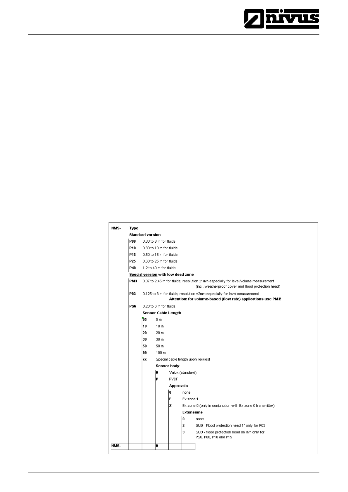
4.2 Device Versions
The NivuMaster Sensors are available in different versions. The tables below
give a brief overview on the various possibilities.
Fig. 4-1 Type key for ultrasonic sensors
®
Instruction Manual
NivuMaster Ultrasonic Sensors
Page 14 NivuMaster Ultrasonic Sensors - Rev. 06 as of 29.07.2011
4.2.1 Flood protection sleeve (Option)
The flood protection sleeve causes an air cushion to form in front of the sensor
face in case of immersion. Electronic components detect this defined condition.
Please observe that measuring however is not possible until the flood situation
has been reached as soon as material is getting into the blanking distance area!
There is a risk of measurement errors if foam should get into the sleeve!
The flood protection sleeve is also available as upgrade kit.
Please observe the following during installation of the flood protection
sleeve (here: P 06/P 10):
1. Clean sensor and flood protection sleeve (surface must be oil-
free).
2. Put sensor into sleeve.
3. Seal remaining gap between sleeve and sensor with silicone.
4. Allow approx. 48 hrs. at 20 °C (68 °F) for hardening.
Fig. 4-2 Flood protection sleeve for P-Series sensors

Instruction Manual
NivuMaster Ultrasonic Sensors
®
NivuMaster Ultrasonic Sensors - Rev. 06 as of 29.07.2011 Page 15
4.2.2 DIN-Flange Versions (Option)
NivuMaster sensors are available in various DIN-Flange versions.
If you should have questions please contact the NIVUS head office.
Fig. 4-3 Dummy flanges according to DIN 2527 for P-Series sensors

®
Instruction Manual
NivuMaster Ultrasonic Sensors
Page 16 NivuMaster Ultrasonic Sensors - Rev. 06 as of 29.07.2011
5 Storing, Delivery and Transport
5.1 Receipt
Please check your delivery according to the delivery note for completeness and
intactness immediately after receipt. Any damage in transit must be instantly re-
ported to the carrier. An immediate, written report must be sent to NIVUS GmbH
Eppingen as well.
Please report any delivery incompleteness in writing to your representative or di-
rectly to NIVUS Eppingen within two weeks.
Mistakes cannot be rectified later!
5.1.1 Delivery
The standard delivery of the NivuMaster Ultrasonic-Sensors contains:
- the instruction manual with the certificate of conformity. Here, all necessary
steps to correctly install and to operate the measurement system are listed.
- 1 Ultrasonic-Sensor
- 2 x screw nuts (G1“ PVC)
Additional accessories depending on order. Please check by using the delivery
note.
5.2 Storing
The following storing conditions must be strictly adhered to:
NivuMaster Sensor:
max. temperature: + 95 °C (203 °F)
min. temperature: - 40 °C (-40 °F)
The devices must be protected from corrosive or organic solvent vapours, radio-
active radiation as well as strong electromagnetic radiation.
5.3 Transport
The Sensors are conceived for harsh industrial conditions. Despite this do not
expose them to heavy shocks or vibrations.
Transportation must be carried out in the original packaging.
5.4 Return
The units must be returned at customer cost to NIVUS Eppingen in the
original packaging.
Otherwise the return cannot be accepted!

Instruction Manual
NivuMaster Ultrasonic Sensors
®
NivuMaster Ultrasonic Sensors - Rev. 06 as of 29.07.2011 Page 17
6 Installation
6.1 General
For electric installation the local regulations in the respective countries
(e.g. VDE 0100 in Germany) must be referred to.
NivuMaster sensor power supply is allowed to be carried out via the NivuMaster
transmitter exclusively.
Before feeding the rated voltage the transmitter and sensor installation must be
correctly completed. The installation should be carried out by qualified personnel
only. Further statutory standards, regulations and technical rulings have to be
taken into account.
The sensor protection rating is IP 68.
Please check if the power supply of the accompanying transmitter must be inte-
grated into the facility’s emergency shutdown conception.
6.2 Installation and Connection of NivuMaster Sensors
6.2.1 General
The sensors mounting place has to be selected according to certain criteria.
Please strictly avoid:
- heat emitting objects (max. ambient temperature: +95 °C (203 °F))
- objects with strong electromagnetic fields (e.g. frequency converters, electric
motors with high power consumption or similar)
- corrosive chemicals or gas
- mechanical shocks
- vibrations
- radioactive radiation
- installation close to footpaths or travel ways
Removing or loosening cable glands results in leakage and causes a failure in
the measurement / the sensor.
No sensor parts are allowed to be removed on principle!
To avoid disturbances from electrical interferences, the sensor cable must not
be laid close to (or parallel to) engine (motor) lines or main power lines.

®
Instruction Manual
NivuMaster Ultrasonic Sensors
Page 18 NivuMaster Ultrasonic Sensors - Rev. 06 as of 29.07.2011
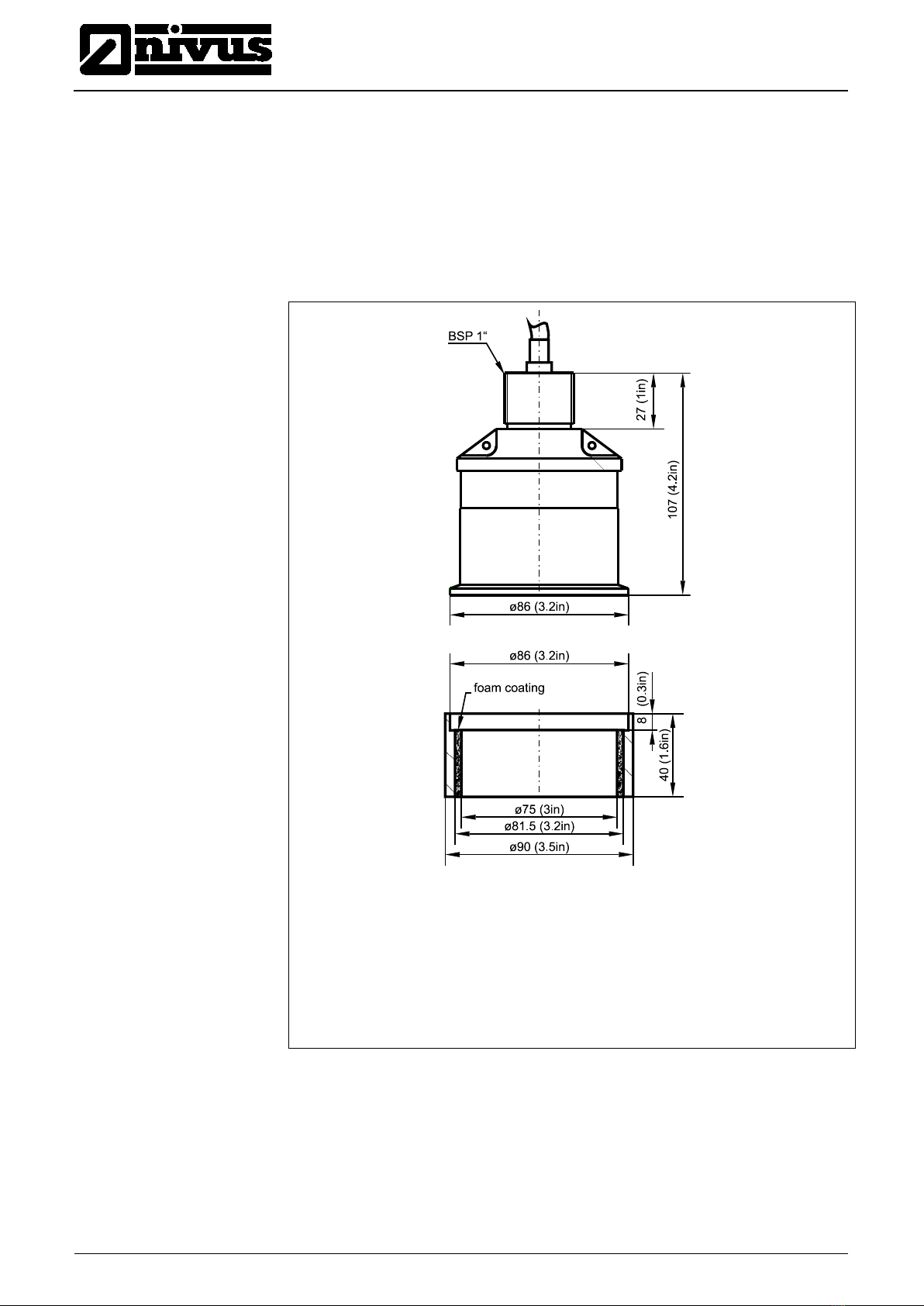
6.2.2 Sensor Dimensions
Dimensions in mm (inch)
1 Protective cover
2 Flood protection sleeve
3 Fastening screws
Fig. 6-1 P-M3 ultrasonic sensor dimensions
Fig. 6-2 P 03 ultrasonic sensor dimensions

Instruction Manual
NivuMaster Ultrasonic Sensors
®
NivuMaster Ultrasonic Sensors - Rev. 06 as of 29.07.2011 Page 19
Fig. 6-3 P 06 and P 10 ultrasonic sensor dimensions
Fig. 6-4 P 15 ultrasonic sensor dimensions

®
Instruction Manual
NivuMaster Ultrasonic Sensors
Page 20 NivuMaster Ultrasonic Sensors - Rev. 06 as of 29.07.2011
Fig. 6-5 P 25 ultrasonic sensor dimensions
Fig. 6-6 P 40 ultrasonic sensor dimensions
Table of contents
Other Nivus Accessories manuals


