Nivus NivuBar Plus II User manual

Instruction manual for
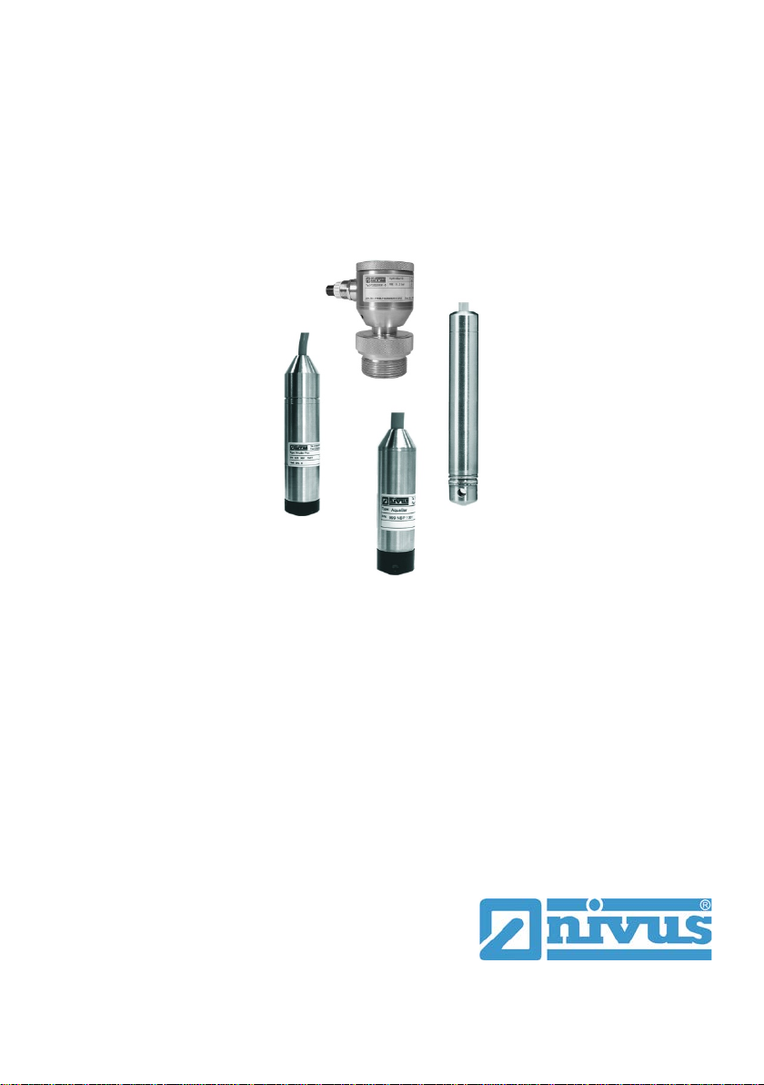
Pressure and Level Sensors:
NivuBar Plus II, NivuBar G II, NivuBar H III,
HydroBar G II, UniBar E II, AquaBar II
rev. 09 / 12.10.2017
Original Instruction Manual – German / rev. 09 / 20.03.2017
NIVUS GmbH
Im Täle 2
75031 Eppingen, Germany
Tel.: 072 62 - 91 91 - 0
Fax: 072 62 - 91 91 - 999
www.nivus.com

page 2 Pressure and Level Sensors - rev. 09 / 12.10.2017
NIVUS AG
Burgstraße 28
8750 Glarus, Switzerland
Phone: +41 (0)55 6452066
Fax: +41 (0)55 6452014
www.nivus.de
NIVUS Austria
Mühlbergstraße 33B
3382 Loosdorf, Austria
Phone: +43 (0) 2754 567 63 21
Fax: +43 (0) 2754 567 63 20
www.nivus.de
NIVUS Sp. z o.o.
ul. Hutnicza 3 / B-18
81-212 Gdynia, Poland
Phone: +48 (0) 58 7602015
Fax: +48 (0) 58 7602014
www.nivus.pl
NIVUS France
14, rue de la Paix
67770 Sessenheim, France
Phone: +33 (0)3 88071696
Fax: +33 (0)3 88071697
www.nivus.fr
NIVUS U.K. Ltd.
Wedgewood Rugby Road
Weston under Wetherley
Royal Leamington Spa
CV33 9BW, Warwickshire
Phone: +44 (0)8445 3328 83
www.nivus.com
NIVUS Middle East (FZE)
Building Q 1-1 ap. 055
P.O. Box: 9217
Sharjah Airport International
Free Zone
Phone: +971 6 55 78 224
Fax: +971 6 55 78 225
www.nivus.com
NIVUS Korea Co. Ltd.
#2502 M Dong, Technopark IT Center,
32 Song-do-gwa-hak-ro, Yeon-su-gu,
INCHEON, Korea 21984
Phone: +82 32 209 8588
Fax: +82 32 209 8590
www.nivus.com
NIVUS Vietnam
21 Pho Duc Chinh, Ba Dinh
Hanoi, Vietnam
Phone: +84 12 0446 7724
www.nivus.com
NIVUS Chile
Viña Cordillera Oriente 4565
Puente Alto, Santiago
Phone: +562 2266 8119
www.nivus.com

Copyrights and property rights
Pressure and Level Sensors - rev. 09 / 12.10.2017 page 3
Copyrights and property rights
This document and its contents are proprietary to NIVUS GmbH and are
not to be reproduced or copied without the express written permission of
NIVUS GmbH.
Violations oblige to compensation.
Important Note
This instruction manual may exclusively - even in parts - be
copied or translated in any other way with the express writ-
ten consent of NIVUS GmbH.
Translation
If the device is sold to a country in the European Economic Area (EEA)
this instruction manual must be translated into the language of the coun-
try in which the device is to be used. Should the translated text be un-
clear, the original instruction manual (German) must be consulted or the
manufacturer contacted for clarification.
Copyright
No part of this publication may be reproduced, transmitted, sold or dis-
closed without prior permission. Damages will be claimed for violations.
All rights reserved.
Names
The use of general descriptive names, trade names, trade-marks and the
like in this manual does not entitle the reader to assume they may be
used freely by everyone. They are often protected registered trademarks
even if not marked as such.

Instruction manual
Pressure and Level Sensors
page 4 Pressure and Level Sensors - rev. 09 / 12.10.2017
1General....................................................................................5
2Safety Instructions.................................................................7
2.1 Used symbols and signal words.........................................................7
2.2 Safeguards and Precautions..............................................................8
2.3 Liability disclaimer..............................................................................9
2.4 User’s Responsibilities.....................................................................10
3Overview and use in accordance with the requirements 11
3.1 Overview..........................................................................................11
3.2 Use in accordance with the requirements ........................................12
3.4 Device identification .........................................................................14
4Technical Data......................................................................16
5Delivery and Transport........................................................19
5.1 Reception inspection........................................................................19
5.2 Delivery............................................................................................19
5.3 Transport..........................................................................................19
5.4 Return ..............................................................................................19
5.5 Installation of spare parts and parts subject to wear and tear..........20
6Construction and Function.................................................21
6.1 Construction.....................................................................................21
6.2 Functional principle ..........................................................................22
6.2.1 General ............................................................................................22
6.2.2 Sensor versions ...............................................................................22
7InstallationInstallation and Connection ............................29
7.1 General Installation Instructions.......................................................29
7.2 Installation........................................................................................29
7.2.1 General ............................................................................................29
7.2.2 Dimensions ......................................................................................31
7.2.3 Connection.......................................................................................40
7.2.4 Pin configuration ..............................................................................42
7.2.5 Circuit...............................................................................................42
7.2.6 Power supply....................................................................................43
8Initial Start-up.......................................................................44
9Maintenance and Cleaning .................................................45
9.1Interval .............................................................................................45
9.2 Cleaning...........................................................................................45
9.3 Dismantling/Disposal........................................................................46
10 Index......................................................................................47
11 Certificates and Approvals.................................................48

General
Pressure and Level Sensors - rev. 09 / 12.10.2017 page 5
1 General
Important
READ CAREFULLY BEFORE USE!
KEEP IN A SAFE PLACE FOR LATER REFERENCE.
Read this instruction manual carefully and completely prior to installation
and connection since it contains relevant information on this product.
Observe the notes and particularly follow the warning notes and safety
instructions.
This Instruction Manual for Pressure and Level Sensors is intended for
the initial start-up or the connection of the sensors and probes depicted
on the title page to NIVUS transmitters.
This Instruction Manual is part of the pressure and level sensor standard
delivery and shall be available to users at any time. The safety instruc-
tions contained therein must be followed.
Keep this manual in a safe place and make sure it is available for the us-
ers of this product at any time.
In case of selling the sensors this instruction manual shall be provided to
the purchaser.
If you should have problems to understand information contained within
this instruction manual either contact the manufacturer or one of the dis-
tributors for further support. The manufacturer cannot be held responsi-
ble for damage to persons or material due to incorrectly understood in-
formation in this instruction.
Detailed information on how to operate the pressure and level sensors in
connection with NIVUS transmitters can be found in the accompanying
transmitter instruction manual.

Instruction manual
Pressure and Level Sensors
page 6 Pressure and Level Sensors - rev. 09 / 12.10.2017
Personnel requirements
Installation, commissioning and maintenance shall be executed only by
personnel meeting the demands as follows:
−Expert personnel with relevant training and appropriate qualification
−Personnel authorised by the plant operator
Qualified personnel
within the context of this documentation or the safety notes
on the product itself are persons who are sufficiently famil-
iar with installation, mounting, starting up and operation of
the product and who have the relevant qualifications for
their work; for example:
−Training, instruction or authorisation to acti-
vate/deactivate, isolate, ground, and mark electric cir-
cuits and devices/systems according to the safety engi-
neering standards.
−Education and instruction according to the standards of
safety engineering regarding the maintenance and use of
adequate safety equipment.
−First aid training
Applicable documentation
For the installation and operation of the complete system extra instruc-
tion manuals or technical descriptions may be required apart from this
manual.
−Instruction Manual for the Transmitter NivuCont Plus
−Instruction Manual for the Transmitter NivuCont S
These manuals are provided with the auxiliary units or sensors and/or
are available as download on the NIVUS homepage.

Safety Instructions
Pressure and Level Sensors - rev. 09 / 12.10.2017 page 7
2 Safety Instructions
2.1 Used symbols and signal words
The general warning symbol indicates the risk of personal
injuries or death. In the text section the general warning
symbol is used in conjunction with the signal words de-
scribed below.
DANGER Warnings against personal damage
Indicates a high-risk, imminently hazardous situation
which will result in death or serious injury if not avoided.
DANGER Danger by electric voltage
Indicates a hazard with a high risk of electric shock which
may result in a life-threatening situation or severe bodily
injury if it is not avoided.
WARNING Warnings against personal injury
Indicates a possible danger with medium risk which may
result in a life-threatening situation or (severe) bodily inju-
ry if it is not avoided.
CAUTION Warnings in low-risk or property damages
Indicates a possible danger with moderate risk which may
result in minor or moderate personal injury or material
damage if not avoided.
Important Note
Indicates a situation which may result in damage at this
instrument if not avoided.
Contains information that should be highlighted.

Instruction manual
Pressure and Level Sensors
page 8 Pressure and Level Sensors - rev. 09 / 12.10.2017
Note
Indicates a situation which not results in personal injury.
2.2 Safeguards and Precautions
WARNING Germ contamination
Please note that due to the operation in the waste water
field the measurement system and cables may be loaded
with dangerous disease germs. Respective precautionary
measures must be taken to avoid damage to one’s health.
Wear protective clothing.
WARNING Observe occupational safety regulations
Before starting installation work, observing the work safe-
ty regulations need to be checked.
Disregarding may lead in personal injury.
WARNING Do not disable safety devices
It is strictly prohibited to disable the safety devices or to
change the way they work.
Disregarding may lead in personal injury.
Important Note
The entire measurement system shall be installed and put
into operation only by trained expert personnel.

Safety Instructions
Pressure and Level Sensors - rev. 09 / 12.10.2017 page 9
2.3 Liability disclaimer
The manufacturer reserves the right to change the contents of this doc-
ument including this liability disclaimer without prior notice and cannot be
held responsible in any way for possible consequences resulting from
such changes.
For connection, initial start-up and operation as well as maintenance of
the unit the following information and higher legal regulations of the re-
spective country (in Germany e. g. VDE regulations) such as applicable
Ex regulations as well as safety requirements and regulations in order to
avoid accidents shall be observed.
The sensors have been constructed considering the standards
EN 60079-0, EN 60079-11 and EN 60079-26.
The safety-related values of pressure/level probes shall be compatible
with the values as specified in the technical data or the Ex approval/EG
type examination certificate.
Interconnecting more than one active equipment unit within one intrinsi-
cally safe circuit may result in different safety-related values. This may
impair intrinsic safety!
All operations on the device which go beyond installation or connection
measures in principle shall be carried out by NIVUS staff or personnel
authorised by NIVUS due to reasons of safety and guarantee.
Operate the Pressure and Level Sensors only in technically perfect work-
ing order.
Improper Use
Not being operated in accordance with the requirements may impair the
safety. The manufacturer is not responsible for failures resulting from im-
proper use.

Instruction manual
Pressure and Level Sensors
page 10 Pressure and Level Sensors - rev. 09 / 12.10.2017
2.4 User’s Responsibilities
Important Note
In the EEA (European Economic Area) national imple-
mentation of the frame-work directive 89/391/EEC and
corresponding individual directives, in particular the di-
rective 2009/104/EC concerning the minimum safety and
health requirements for the use of work equipment by
workers at work, as amended, are to be observed and
adhered to.
In Germany the Industrial Safety Ordinance must be ob-
served.
Make sure to have a local operating permit available and observe the
associated conditions.
In addition to this you must observe environmental requirements and lo-
cal laws on the following points.
−Personnel safety (accident prevention regulations)
−Safety of work materials and tools (safety equipment and mainte-
nance)
−Disposal of products (laws on wastes)
−Disposal of materials (laws on wastes)
−Cleaning (cleansing agents and disposal)
−Environmental requirements
Connections
Operators shall make sure prior to operating the Pressure and Level
Sensors that during installation and initial start-up the local regulations
(such as regulations for electrical connection) are observed.

Overview and use in accordance
with the requirements
Pressure and Level Sensors - rev. 09 / 12.10.2017 page 11
3 Overview and use in accordance with the requirements
3.1 Overview
1 NivuBar Plus II
2 NivuBar G II
3 NivuBar H III
4 HydroBar G II
5 AquaBar II
6 AquaBar BS
7
UniBar E II (stainless steel enclosure)
8
UniBar E II (with plug)
Fig. 3-1 Overview of pressure and level sensors

Instruction manual
Pressure and Level Sensors
page 12 Pressure and Level Sensors - rev. 09 / 12.10.2017
3.2 Use in accordance with the requirements
Note
The sensors for pressure and level measurement are
exclusively intended to be used for purposes as described
above. Modifying or using the devices for other purposes
without the written consent of the manufacturer will not
be considered as use in accordance with the require-
ments.
Damages resulting from this are left at user’s risk.
The sensors are used for pressure and level measurements (depending
on type, i. e. submersible or screw-in sensor). Here the allowed maxi-
mum values, as specified in chapter “4 Technical Data”, must be strictly
kept. All cases which vary from these conditions and are not passed by
NIVUS GmbH in writing are left at owner’s risk.
Ex Approval
The sensors (except for AquaBar BS) are designed to be used in areas
with explosive atmospheres (zone 0).
Important note
Necessarily observe point [17] of the according Ex certifi-
cate/EG type examination certificate.
Point [17] stipulates particular conditions for intrinsically
safe operation.

Overview and use in accordance
with the requirements
Pressure and Level Sensors - rev. 09 / 12.10.2017 page 13
Approval
AquaBar II,
UniBar E II
NivuBar H III
NivuBar Plus II,
NivuBar G II,
HydroBar G II
II 1G Ex ia IIC T4 Ga
II 1D IIIC T85°C Da
II 1G Ex ia IIB T4 Ga
II 1D Ex ia IIIC T85°C
Da
II1G, II 1/2G or II 2G
Ex ia IIC/IIB T6/T4 Ga
Ga/Gb or Gb
II1D Ex ia IIIC T85°C
Da
Approval number:
IBExU11ATEX 1046X
Approval number:
IBExU11ATEX 1047X
Approval number:
IBExU05ATEX 1193X
Ui = 28 V
Ii = 93 mA
Pi = 660 mW
Ci = can be ignored
Li = can be ignored
C GND = 27 nF
Ui = 28 V
Ii = 93 mA
Pi = 660 mW
Ci = 13,2 nF
Li = 5 µH
C GND = 27 nF
Ui = 28 V
Ii = 93 mA
Pi = 660 mW
Ci = 27 nF
Li = 5 µH
C GND = 27 nF
DANGER
Risk of explosion due to zone entrainment
The cable duct between probe and transmitter shall be
gas-tight.
To avoid zone entrainment always ensure gas-tight instal-
lation of probes featuring 1/2G approval in the zone parti-
tion wall.
Otherwise there is a risk of explosion.
Note
The Ex approvals are only valid in connection with the
respective indication on the probes or the sensor name-
plate.
For installation and initial start-up the conformity certifi-
cates and test certificates of the respective authorities
must be followed.

Instruction manual
Pressure and Level Sensors
page 14 Pressure and Level Sensors - rev. 09 / 12.10.2017
3.4 Device identification
The instructions contained within this manual are valid only for the types
of sensors specified on the title page.
The name plate is fixed on the side of the enclosure and contains the fol-
lowing:
−Name and address of the manufacturer
−CE label
−Information on type and series, serial no. if available
−Year of construction
−Ex-version probes are additionally labelled with the Ex protection ID
as specified in chapter “3.2 Use in accordance with the require-
ments”.
In case of enquiries and ordering replacement parts it is important to
specify article number as well as the serial number of the respective sen-
sor. This ensures correct and quick processing.
Note
Check the delivered instrument for accordance with your
order by identifying the nameplate.
Check the nameplate for correct specification of the pow-
er supply.

Overview and use in accordance
with the requirements
Pressure and Level Sensors - rev. 09 / 12.10.2017 page 15
Abb. 3-1 Nameplates of the Pressure and Level Sensors

Instruction manual
Pressure and Level Sensors
page 16 Pressure and Level Sensors - rev. 09 / 12.10.2017
4 Technical Data
NivuBar Plus II
NivuBar G II
NivuBar H III
Submersible sensors
Power supply (U
B
)
12…36 V DC
intrinsically safe current circuit 14…28 Volt / 93 mA
(Pi= 660 mW)
Measurement range
See nameplate
Measurement signal
(2-wire-technology)
4…20 mA
Load (max. 24 Volt)
600 Ohm / R
max
= (U
B
- 12) / 0.02 A
Connection cable
Polyurethane cable shielded 2x 0.14 mm²; d = 9 mm
Enclosure
Material: V4A
Protection: IP68
Measurement membrane
Ceramics 96 % Al
2
O
2
Ex-Approval
See permissible EC-certificate/EG-type examination
certificate in chapter “11 Certificates and Approvals“
Operation temperature
Ex:
Zone 0 = -10…+60 °C at Patm 0.8…1.1 bar
Zone 1 (and higher) = -10…+70 °C
None-Ex:
-25…+125 °C
Storage temperature
-25…+125 °C
Max. humidity
80 %, non condensing
Store the probes in a safe place protected from corro-
sive or organic solvent vapours, radioactive radiation
and strong electromagnetic fields.

Technical Data
Pressure and Level Sensors - rev. 09 / 12.10.2017 page 17
AquaBar II
AquaBar BS (none-Ex)
Submersible sensors
Power supply (U
B
)
12…36 V DC
intrinsically safe current circuit 14…28 Volt / 93 mA
(Pi= 660 mW)
Measurement range
See nameplate
Measurement signal
(2-wire-technology)
4…20 mA
Load (max. 24 Volt)
600 Ohm / R
max
= (U
B
- 12) / 0.02 A
Connection cable
Polyurethane cable shielded 2x 0.14 mm²; d = 9 mm
Enclosure
Material: V4A
Protection: IP68
Measurement membrane
Stainless steel
Ex-Approval
See permissible EC-certificate/EG-type examination
certificate in chapter “11 Certificates and Approvals“
Operating temperature
AquaBar II:
Zone 0 = -20…+60 °C at Patm 0.8…1.1 bar
Zone 1 (and higher) = -20…+70 °C
AquaBar BS (none-Ex):
-10…+70 °C
Storage temperature
-25…+70 °C
Max. humidity
80 %, non-condensing
Store the probes in a safe place protected from corro-
sive or organic solvent vapours, radioactive radiation
and strong electromagnetic fields.

Instruction manual
Pressure and Level Sensors
page 18 Pressure and Level Sensors - rev. 09 / 12.10.2017
HydroBar G II
UniBar E II
Pressure sensors
Power supply (U
B
)
12…36 V DC
intrinsically safe current circuit 14…28 Volt / 93 mA
(Pi = 660 mW)
Measurement range
See nameplate
Measurement signal
(2-wire-technology)
4…20 mA
Load (max. 24 Volt)
600 Ohm / R
max
= (U
B
- 12) / 0.02 A
Enclosure
Material: V4A
Protection: IP67 (field enclosure), IP65 (enclosure
with plug connection DIN 43650);
cable gland: PG13.5 (field enclosure), PG9 (with plug
connection DIN 43650)
Measurement membrane
Ceramics 96 % Al
2
O
2
(HydroBar G II);
Stainless steel V4A (UniBar E II)
Ex-Approval
See permissible EC-certificate/EG-type examination
certificate in chapter “11 Certificates and Approvals“
Operation temperature
HydroBar GII (Ex):
Zone 0 = -20…+60 °C at Patm 0.8…1.1 bar
Zone 1 (and higher) = -25…+70 °C
HydroBar GII (None-Ex):
-40…+85 °C
UniBar EII (Ex):
Zone 0 = -20…+60 °C at Patm 0.8…1.1 bar
Zone 1 (and higher) = -20…+70 °C
UniBar EII (None-Ex):
-40…+85 °C
Storage temperature
-40…+100 °C
Max. humidity
80 %, non condensing
Store the probes in a safe place protected from corro-
sive or organic solvent vapours, radioactive radiation
and strong electromagnetic fields.

Delivery and Transport
Pressure and Level Sensors - rev. 09 / 12.10.2017 page 19
5 Delivery and Transport
5.1 Reception inspection
Check the packaging for visible damage immediately after receipt. Any
possible damage in transit shall be instantly reported to the carrier.
Furthermore a written report shall be sent to NIVUS GmbH in Eppingen.
Incomplete deliveries shall be reported in writing either to your local rep-
resentative or directly to the NIVUS head office in Eppingen within two
weeks.
Note
Mistakes cannot be rectified later.
5.2 Delivery
The standard delivery of the Pressure and Level Sensors contains:
−Pressure or Level Sensor corresponding to the shipping documents
−Instruction manual including the certificate of conformity and approv-
als; it contains any relevant information on how to operate the Pres-
sure and Level Sensors
Additional accessories are depending on your order. Please check by us-
ing the delivery note.
5.3 Transport
Sensor and Transmitter are conceived for harsh industrial conditions.
Despite this do not expose them to heavy shocks or vibrations. Transpor-
tation must be carried out in the original packaging.
5.4 Return
In case of a required reshipment return the unit at customer cost to
NIVUS GmbH in Eppingen using the original packaging.
Insufficiently franked shipments will not be accepted.

Instruction manual
Pressure and Level Sensors
page 20 Pressure and Level Sensors - rev. 09 / 12.10.2017
5.5 Installation of spare parts and parts subject to wear and
tear
We herewith particularly emphasise that replacement parts or accesso-
ries not supplied by NIVUS moreover are not certified and approved by
NIVUS too. Installation and/or the use of such products hence may nega-
tively influence predetermined constructional characteristics of the
measurement system or even lead to instrument failures.
NIVUS cannot be held responsible for any damage resulting due to the
use of non-original parts and non-original accessories.
This manual suits for next models
5
Table of contents
Other Nivus Accessories manuals
Popular Accessories manuals by other brands

Slazenger
Slazenger S000154 Assembly, Installation, Care, Maintenance, and Use Instructions

PCB Piezotronics
PCB Piezotronics ICP 208C02 Installation and operating manual

TEKTELIC Communications
TEKTELIC Communications Kona All-in-One Home Sensor user guide

SunSetter
SunSetter EASYSHADE Replacement

AND
AND Weighing Indicator AD-4329 OP-02 instruction manual

Rittal
Rittal SK 3303.470 Assembly and operating instructions