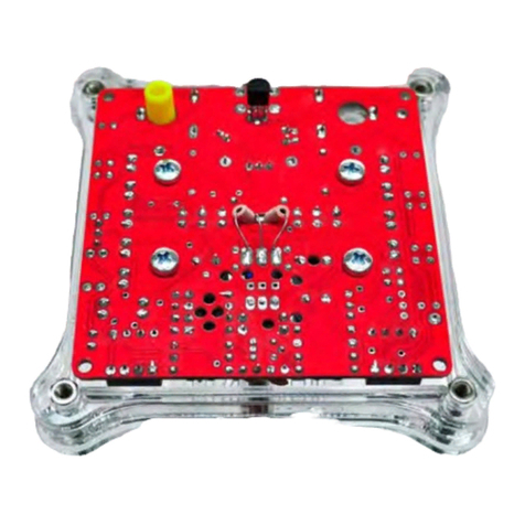
Nixie Temp n Glow IN-16 User manual

Temp’n’GlowIN‐16NixieThermometerDocumentation
1
"Temp'n'Glow",thenewsecretamongnixie
enthusiasts,isaNixietubethermometerfortheslim,beautifulIN‐16tubes.
Fast,secureinstallationwithoutanyadjustmentarethefeaturesofthiskitas
wellasitsmodernlook.
Butthetechnologyisstateoftheart,too.
Asmartmenusystemmakesoperationeasy.
Adjustablechangeinterval,errordetectionandmanyotherfeaturesarestandardon
"Temp'n'Glow".
Ahigh togo
lightistheso‐called"CathodePoisoningPrevention".Thisfeatureallowsthedigits
throughcertainperiods(slot‐machineeffect).
Thiswillprotectthecathodedepositsandasaresultofthatyourtubeslivelonger.
Enjoyyour"Temp'n'Glow"Nixietubethermometer!
This document is copyrighted.
No parts of this documentation may be used commercially.

Temp’n’GlowIN‐16NixieThermometerDocumentation
2
Tableofcontents
1SafetyandLegalWarnings .....................................................................................................3
2Features ........................................................................................................................................4
3Functions ......................................................................................................................................4
4Settings..........................................................................................................................................5
5Displaylimits ..............................................................................................................................6
6Errorindication..........................................................................................................................6
7SpecialNotesontheIN16tubes..........................................................................................6
8PartList .........................................................................................................................................8
9Soldering.......................................................................................................................................9
10 MountingoftheNeonglowlamp.................................................................................... 10
11 Solderthetubes.................................................................................................................... 11
12 SoldertheLeds...................................................................................................................... 12
13 SwitchingofftheundersideLEDillumination........................................................... 13
14 Mountingthetemperaturesensors............................................................................... 14
15 Maximumlengthofsensorcables.................................................................................. 14
16 Connectingthethermometertopower........................................................................ 14
17Specifications......................................................................................................................... 15

Temp’n’GlowIN‐16NixieThermometerDocumentation
3
1 Safety and Legal Warnings
DANGER:Thiscircuitdesignincludesaswitching‐modevoltageconverterwhichgenerates170VDC.
experiencedin
Therefore,assemblyshouldbeattemptedonlybycompetentqualifiedpersonnel
electronicsassemblyandhighvoltagesafety.
Safeassemblyandoperationofthiskitiscompletelythereader’sresponsibility.
Readinstructions:Allthesafetyandoperatinginstructionsshouldbereadcarefullyandcompletelybefore
hethermometerisoperated.Heedwarnings:Allwarningsontheapplianceandintheoperating
nstructionsshouldb
t
ieadheredto.
RetainInstructions:Thesafetyandoperatinginstructionsshouldberetainedforfuturereference.
nd
•Ifoneofthetubesisbrokenordamaged,immediatelypullthepowerplugoutofthethermometera
contactthecustomersupport.
•Thetubesaremadeofglassandareconsequentlyveryeasytobreak.Becauseoftheirfragility,itis
ofbeingstruck
importantthatyoukeepthethermometerinasafeplacefreefromthepossibility
inadvertently.
•Nopartofthethermometermaybeswallowedorinsertedintobodyopenings.
•Thepowersupplymaynotbeswallowedorinsertedintobodyopenings.
n
•Nopartofthethermometerorthepowersupplymaybeusedforotherpurposeotherthandescribedi
thisusermanual.
•Waterandmoisture:Thethermometershouldbekeptinadryroomfreefromhumidityanddust.The
thermometershouldnotbeusednearwater–forexample,nearabathtub,washbowl,kitchensink,
d
laundrytub,inawetbasement,nearaswimmingpool,inasauna,etc.Inadditionthethermometershoul
bekeptoutofdirectsunlightandhightemperatures.
orhave
•Objectandliquidentry:Careshouldbetakensothatthethermometerdoesnotfallintoliquids
themspilledoverthethermometer.
•Donotusethisapplianceforanythingotherthantheintendeduseasdescribedinthemanual.
•Immediatelypullthepowerplugoutofthethermometerandcontactthecustomersupportifthe
mance.Inthiscase
appliancedoesnotappeartooperatenormallyorexhibitsamarkedchangeinperfor
donotrunthethermometeragain!
•Thisthermometerisnotatoy!Keepthisthermometeroutofthereachofchildren.
Payattentionthatthisthermometershallonlybetouchedbypeoplewhohavecompletelyreadand
•
understoodtheusermanual.
IMPORTANT:Pleasefollowtheassemblystepswithextremecare.Pleaseoperatethethermometeronly
inanenclosedhousingwhichpreventscontactwiththedangerousvoltagespresentonbothprinted
circuitboards(PCB).
DISCLAIMER:Theinformationinthisdocumentisprovidedstrictly'asis'.Itisherebystatedthatthiskitis
tobeassembledonlybyexperiencedelectronicsengineers.Notroubleshootinginformationisprovided.
Readersshouldnotattempttobuildthiskitand/ordesignunlesstheyarecompetentatelectronics
assemblyandunderstandthedangersofmainsvoltages.Further,www.nixieclocks.detakesno
responsibilityforanypossiblepersonalorpropertydamage.Noresponsibilityisacceptedforanydamage,
injury(howeverserious)ordeath.Innoeventshallwww.nixieclocks.debeheldliabletoyouoranythird
partiesforanyspecial,punitive,incidental,indirect,consequential,oranyotherdamagesresultingfrom
heassemblyoruseofthiskitand/ordesign.Theassembledunitshouldbeproperlyencasedtoprevent
t
contactwithhighvoltages.
AllapplicableUL,CCE,VDEandlocalregulationsmustbeconsidered.Commercialuseofthekit,circuit
designs,softwareoranypartsthereofrequiresexpresswrittenpermission.

Temp’n’GlowIN‐16NixieThermometerDocumentation
4
2 Features
‐Inputvoltagefrom10‐14VoltDC
‐Lowcurrentconsumptionis150mA
forworldwideuseavailable
ersupplytechnology
‐Standardpoweradapter
‐veryhighefficiencybyusingmodernswitchingpow
orlighting
ionbyLEDlight(canbeswitchedoff)
‐switchableflo
‐pcbilluminat
‐easytobuild
‐nosmdparts
ermenu
sortobeswitchedoff
‐sophisticatedsoftwarewithus
‐Crossfadingselectablein5differentlevel
prevention
‐Cathodepoisoning
‐Upto2temperaturesensorsconnectable
‐"minussigntube"
replacedbyleftdecimaldot
peraturesensororfaultysignal
‐"minussigntube"canalsobe
m
‐Errordetectionforfaultyte
‐small,compactcircuitboard
‐Simple2‐buttonoperation
mperatureselectable
‐includingmountingspacers
insideandoutsidete
‐alternatingcyclebetween
‐Allsettingsarestoredincaseofpowerfailure
ssary
F
‐noadjustmentnece
‐measuringrangefrom‐55°Cto+85°C/‐67°Fto+99°
‐Displayin°Cor°F
Longcablesavailableforexternalsensorupto10m
Pre‐assembledtemperaturesensorcableavailablefromwebshop
‐
‐
3 Functions
Preliminaryhint:
emperaturesensor1=insidetemperature
emperaturesensor2=outsidetemperature
T
T
Leftdecimaldotofthelefttube:
asnofunctioniftheminussignneonlampandR42areinstalled.
howsanegativesignofthetemper inus‐neonlampisinstalledbutR42isinstalled.
H
Satureifnom
ightdecimaldotofthelefttube:
RNofunction
Leftdecimaldotoftherighttube:Nofunction
isdisplayed.
Rightdecimaldotoftherighttube:
e
.
Itshowswhethertheinsideortheoutsidetemperatur
tlightsupwhentheoutsidetemperatureisdisplayed
tisnotlitwhentheindoortemperatureisdisplayed.
I
I
Display:
°Cor°F,dependingonwhichunitinthemenuis
Thetwotubespermanentlyshowthetemperaturein
set.
Thedisplayistwodigits–nodisplayof½adegree.
Atnegativetemperature,theminussign(neonlamporleftofthedecimaldotoflefttube)ison.

Temp’n’GlowIN‐16NixieThermometerDocumentation
5
T
(
heinsideandoutsidetemperatures(orviceversa)areshownintheintervalthatissetinthemenu
changeinterval)
Menu/Settings:
"Menu"buttonintheusermenuisasfollows(circlemenu):
emperatureDisplay>>Changeinterval>>crossfadingvalue>>numberofprobes>>unit>>CP
T
Prevention
fter"CPPreventionisshownthemenugoesbacktoTemperaturedisplayifyoupresstheMenubutton
gain.
A
a
Themenuisshownby
thelefttubeasfollows:
1=changeinterval
Fadingvalue
es
2=Cross
3=numberofprob
=Unit
4
5=CPPrevention
Whi yo
le uareinthemenuthefollowingsettingsare:
ds
‐CrossfadingandCPPreventionaregenerallydeactivated.
‐Thedecimaldotoftherighttubeflasheswithanintervalof0.25secon
.
‐Theminussignresp.theleftdecimaldotofthelefttubeisturnedoff
Afterselectingthemenuitem,the"Set"buttonisusedtochangethevalues.
Thisvalueisindicatedintherighttube.Eachpressofthebutton"Set"incrementsthevaluebyonestep.
fterhavingreachedthehighestvalue,thevalueserieswillstartagainfromthebeginning.Subsequently,
llsettingsaredescribed.
A
a
4 Settings
„1“=changeinterval
rebythevalueofxistherange1‐9(inseconds).
nside/outside/oronlyoneofthem)isupdatedatarangeof1‐9seconds.
Thedisplayshows"1x"whe
aluex=Thetemperature(i
actorysetting=2seconds.
V
F
astherangefrom0‐5.
„2“=CrossFadingvalue
wherebythevaluexh
ollowingmeanings:
Thedisplayshows"2x"
Thevaluesofxhavethef
f
0=CrossFadingisof
1=veryfastcrossfading
rysetting)
2=CrossFadingfast
3=Crossfadingfast(facto
=slowcrossfading
4
5=veryslowcrossfading
Thecross‐fadingaffectsalldigitsofthetubes,theminussign(ortheleftdecimaldotofthelefttube)and
therightdecimaldotoftherighttube.
heCrossFadingisgenerallynotactivewhenscrollingthroughduringtheCPProtection,orwhileyouare
nthemenuandwhileanerrorisdisplayedbytheleftdecimaldot.
T
i
„3“=Numberofsensors
Thedisplayshows"3x",wherebythevaluexhastherangefrom1‐2.
Thevaluesofxhavethefollowingmeanings:
1=onetemperaturesensorisconnectedtosocket1orsolderedonthepcb
2=onetemperaturesensorisconnectedtoasocketorsolderedonthepcbandasecondtemperature
ensorisalsoconnectedtosocket2orsolderedonthepcb(theusualwayforoutdoortemperature
easurement)‐(factorysetting)
s
m

Temp’n’GlowIN‐16NixieThermometerDocumentation
6
4=Units
Thedisplayshows"4x",wherebythevaluexhastherangefrom1‐2
(factorysetting)
.
Thevaluesofxhavethefollowingmeanings:
=Thetubesshowthetemperatureintheunit°C
=Thetubesshowthetemperatureintheunit°F
1
2
astherangefrom0‐1.
5=CPPrevention
x"wherebythevaluexh
ngs:
Thedisplayshows"5
Thevaluesofxhavethefollowingmeani
=Preventionisoff
0
1=CPPreventionison(factorysetting)
IfCPpreventionisswitchedon,theCathodePoisoningPreventionisexecutedevery5minutes.
Thisisdoneasfollows:
ttubeandtherightdecimaldotoftherighttubeis
Theminussignortheleftdecimaldotofthelef
switchedon.
Thedigits0‐9arescrolledthroughbothtubes.
urationofthescrolloperation:4seconds
fterhavingdonethatthedisplaywillshowthetemperaturesagain.
D
A
5 Display limits
I
fthe(theoretical)temperatureisbelow‐99orover+99°Cor°Fthedisplaystillshows‐99to+99.
6 Error indication
Ifoneofthesensorisnotconnectedorproducesabadsignal,then"99"isdi
heleftdecimalpointblinksleftintherhythmof0.25seconds(nocross‐fadi
herightdecimalpointoftherighttuberemainsunchangedinitsfunction.
splayedandtheminussignor
ng).
t
T
7 Special Notes on the IN-16 tubes
ThereareseveralvariantsoftheIN‐16tubes.OnehasaholewithØ4mminthespacer,theotherhasnot.
Hereyoucanseethisdifference:
Withhole:withouthole
fyoufitanyunderbodylightingtubes,thisdifferenceisnotimportanttoyou.However,ifyouinstallan
I
underbodylighting,youhavetorefertothefollowing.
Ifyouusetheversionwithaholeinthespacer,thereisnoneedtochangeanything,becausetheLED
exactlyfitsintothishole.
Butifyouusetheversionwithoutthehole,thenyouhavetodrillaholeofØ4,5mmintothemiddleofthe
spacer.Todoso,slideawaythespacerfromthetubeanddrillthehole.
Note:FromNocrotecyougetmatchedtubesetsWITHholeinspacerfortheLEDs(HERE)

Temp’n’GlowIN‐16NixieThermometerDocumentation
7
Alittlehinttomountthetubes:
holesinthespacer.
Afteryouhavedrilled,youneedtoconnectthetubewiresthroughthe
hiscaneasilybedonebya„spiralstaircasecut“ofthewires.
henthethreadingintothespacerandtheboardwillbemucheasier.
T
T
PinoutIN‐16seenfromtop
Stepcutofwires

Temp’n’GlowIN‐16NixieThermometerDocumentation
8
8 Part List
Part No Pieces Description
BRD1 1 pcb
ASP 2 Adhesive pads
C01 1 Capacitor 1 nF
C10-C16 7 Capacitor 100 nF
C31 1 Electrolytic-Capacitor 4.7µF, U=250V
C23 1 Capacitor-Capacitor 220µF/25V
CR1 1 Resonator, 3-pin, 4MHz
D1 1 Diode UF4004
D2 1 Diode, 1N4004
H1-H4 10 Screw M3x6mm
H1-H4 4 Distance holder M3 15 mm
IC5 2 Bolt, M3
IC1-2 2 74141 or similar
IC3 1 ATtiny461-20PU
IC3 1 IC-socket 20 pin
IC4 1 MC34063A
IC5 1 Regulator, 5Volt, 1A, 7805
IC6 1 DS18S20 Temperature sensor with cable (1 meter)
L1 1 Coil 330 µH / 1,4 A
R10-R11 2 Resistor, 180 Ohm
R20 1 Resistor, 390 Ohm
R30-R31 2 Resistor, 2,2k
R32-R33 2 Resistor, 4,7k
R38 1 Resistor, 8,2k
R40-R43 4 Resistor, 16k - R42 resistor not needed if you do not use left decimal point in left tube
R50-R51 2 Resistor, 68k
R60 1 Resistor, 180k
R70 1 Resistor, 1,1M
S1-S2 2 Push button 3.5x8, 35mm
T1-T2 2 Transistor MPSA42
T3 1 FET IRF630, mounted on pcb
X1-X2 2 Connector for temperature sensors, angled, 2,54mm, 3 pin
JP1 1 Jumper Header, 2 pin, angled
JP1 1 Jumper black, 2,54 mm
X3 1 Socket for power supply plug (5,5mm / 2,5 mm)
You get a complete set of 2 IN-16 tubes with hole in spacer, 2 LEDs and the Minus
Glow Lamp from www.nocrotec.com

Temp’n’GlowIN‐16NixieThermometerDocumentation
9
9 Soldering
Attention:Ifyouhavepurchasedtheacryliccasefor
documentati
thethermometer,pleasereadthat
onfirst!
Firstsolderalltheflatcomponentssuchasresistorsanddiodes.
ResistorR42:Thisisonlyusedifnoglowlamp(GL1),buttheleftdecimalpointofthelefttubeisusedas
anegativeindicator.
IfyouusetheGL1glowlamp,R42isnotmounted.
ThensoldertheICs.IC3issocketed,sosolderthesocketherefirst.WhensolderingtheICspleasewatch
utforthemarkingthatyoufindontheICandonthepcb.ThenL1,thecapacitors,theresonatorCR1and
hecoilaresolderedin.Theresonatorhasnopolarity.
o
t
Figure1resistoranddiodesmounted
Figure2jumperpins,capacitorsmounted
NowsolderthetransistorsT1,T2,T3andIC5.T3andIC5haveaheatsink.Thecomponentsareinstalled
horizontallyandaresecuredwithM3x6screwsandM3nutsonto the board. This is to cool the
components.Thentheconnectionsforthetemperaturesensors,thepushbuttonsandthepowersupply
connectoraresoldered.Whenyousolderthepowersupplyconnectormakesurethatitisflushtotheback
ofthepcb.Thisisimportant,ifyouconsidertouseouracrylichousing.

Temp’n’GlowIN‐16NixieThermometerDocumentation
10
Figure3pcbnearlyready
Nowturnthecircuitboardandsoldertheholderfortheglowlamp,ifyouwish.Youcanmounttheneon
lowlampwithouttheholder.Thewiresoftheneonglowlampshouldbeisolatedwithshrinkingtubeto
reventashortcircuit.
g
p
10 Mounting of the Neon glow lamp
‐Cutfuseholdertab
ts
ter1mm)
‐Cutthefuseholdercontac
ire(diame
‐Stretchsilverw
‐Solderwirefromtherear
‐Bendthewires
‐Pull2piecesofshrinkingtube(21mm)overtheglowlampwiresandshrink
erandshrink
kertopreventamirroreffect.
‐Pullapieceofshrinkingtube(18mm)overthewireofthehold
Blackenthefronttabsoftheholderwithablackpermanentmar
Solderholderintotheboard(distanceissetbyshrinkingtube)
‐
‐
Buildingtheglowlampholder

Temp’n’GlowIN‐16NixieThermometerDocumentation
11
11 Solder the tubes
Next,thetubesaresoldered.Thetubeisnowgettinga"stepcut"sothewirescanbeputintotheholeson
thepcbmoreeasily.Tobesurethatthetubeissolderedcorrectlyintotheboarditisimportanttoknow
wheretheanodeis.
Figure4The"stepcut"
Theanodeismarkedwhiteandyoufinditatthebackofthetube.Youcanseethiseasilyinthepicture
below.
Figure5Anodemarkedwhite–tubelayoutIN‐16
Thelongestwireafterthe“stepcut”shouldbetheanodewire.Seewherethiswiregoes:
Figure6Anodemarkedonthepcb

Temp’n’GlowIN‐16NixieThermometerDocumentation
12
Sostartwiththiswireandputtherestofthemintotheotherholesontheboard.Donotcrossanywires
Allholesholdwiresafterthetubehasbeenmounted.Noholeisfree!
lignthetubesrectangular.Youshouldfirstsolderonlytwowiresandchecktheangle.Nowsolderthe
estofthewiresandcutherestnottooclosetothepcb.
.
A
r
Figure7tubesandglowlampmounted
12 Solder the Leds
B
eforeyousoldertheLeds,youhavetobendtheaccordingtothefollowingsketch.

Temp’n’GlowIN‐16NixieThermometerDocumentation
13
Figure8LEDbent
SoldertheLed’ssothattheanodegoesinthehole"A"andthecathodeinthehole"K".Theanodeisthe
longerwireoftheLED.Thediodemustlookthroughtheholeintheboard.Ithastobeplacedentirelyon
thetubefloorsothatthebluelightcanbeclearlyseen.Ifthedistanceistoolong,thebluelig tscannotbe
seenwell.
h
PleasebecarefulthatthewiresoftheLEDdonottouchthetubecontacts!!
Figure9LEDsoldered
13 Switching off the underside LED illumination
TheLedsilluminatetheundersideoftheboard,creatingabeautifuleffectinanacrylicenclosureatnight.
fyoudonotwanttheeffect,youcaneasily„switch“thatoff.Withthekityouhavereceived2adhesive
I
pads. Theycansealthelightstowardsthebottomandthusisblockingthelightdownwards.
Toturnofftheunderbodylightingyoukneadtheadhesivepadsforhalfaminuteinyourfingersandthen
formthemintoaball.PresstheballscarefullytotheLEDasshownintheFigurebelow.
ecarefulnottopressthewiresfromtheLEDtothepinsoftheNixietubes.Makesurethatthepinsofthe
ubesarecutshort.
B
t
Figure10adhesivepadsmountedtopreventunderbodylighting

Temp’n’GlowIN‐16NixieThermometerDocumentation
14
14 Mounting the temperature sensors
Youcanconnectoneortwosensorstoyourboard.
Thetemperaturesensor(IC6ontheboard)shouldnotbesolderedbecausethetemperatureishigherin
heimmediatevicinityoftheboardthantheroomtemperatureandthusthetemperaturewouldbe
t
incorrect.Thiscomponentpositionisonlyfortestingpurposes.
readings.
lwaysconnectthetemperaturesensorsusingshieldedcabletotheboardforaccurate
nsorandaplugconnected.
A
Withyourkityougetareadymadecable(1meter)withase
Thecable(s)areconnectedtotheterminalsX1and(or)X2.
oucanalsomakeacableyourself.Pleasedothataccordingtoaspecialdocumentationthatisavailable
ordownloadfromourwebsite.
Y
f
15 Maximum length of sensor cables
Thethermometerisdesignedforamaximumcablelengthof10meters.
Pleaseonlyusethecablesfromtheshop.Otherwiseyoumightgetdisturbancesinthecapacityofthe
cabledatatransfer.
orshortcables(1meter),youcanuseyourown2pin,fullyshieldedcable.Butwerecommendthecable
romourwebshop.
F
f
16 Connecting the thermometer to power
Allnecessarysettingscanbemadeusingthemenusystem.Thethermometermustbemountedina
housingsothatthePCBandthecomponentsareprotectedagainstcontact.
nstallthe4spacersasfeet.Pleasecheckallsolderjointsclosely.Pluginthepowersupplyanddonot
I
touchanythingontheboard(170voltsDC).
Theinitializationshouldstartnowandthetemperature(s)shouldappear.
Duringpowerupthecircuitneedsabout2secondstoinitialize.Duringthistime,thedisplayshowsan
ndefinitenumberofvalues.Thenthecorrecttemperatureisdisplayed.Ifnot,refertotheerror
escription(chapter3ofthisdocumentation)
i
d
ThethermometermustbemountedinahousingsothatthePCBandthecomponentsareprotected
againstcontact.

Temp’n’GlowIN‐16NixieThermometerDocumentation
15
17 Specifications
Minimuminputvoltage:10V
Nominalinputvoltage:12V
A
Maximuminputvoltage:14V
m
Maximuminputcurrentat12V:150
12V:1.8W
Maximuminputpowerat
Measuringrange:‐55°Cto+99°C
eof‐10°Cto+85°C
Range:‐67°Fto+99°F
g
Tolerance:±0.5°Cintheran
Overallwidthmodule:97mm
otaldepthModule:67mm
otalheightmodule:65mm
T
T
allrightsreserved–www.nixiekitworld.com ‐April2012
Table of contents
Other Nixie Thermometer manuals
Popular Thermometer manuals by other brands

Steak Champ
Steak Champ 3-COLOR quick start guide

Kyoritsu Electrical Instruments Works, Ltd.
Kyoritsu Electrical Instruments Works, Ltd. KEW 5515 instruction manual
Unit
Unit UT321 operating manual
Master cool
Master cool 52228 operating instructions
Unit
Unit UT301A operating instructions

MasterChef
MasterChef VRD919102100 user manual
