NJ PHILLIPS Powermaster User manual

15ml Variable Dose Powered Injector

PAGE 2
IMPORTANT SAFETY WARNING
The injector, associated equipment and injectable chemicals
each pose inherent risks to human health and safety if used
incorrectly and without appropriate safety precautions.
All owners of the injector, including employers and self-
employed persons, are reminded of their strict obligations
to ensure the health and safety of employees and all other
persons in the place (ie workplace) in which the injector,
associated equipment, and veterinary chemicals are used
and stored.
In particular, employers and self-employed persons MUST
make appropriate arrangements to ensure safety and the
absence of risks to health in connection with the use, handling,
storage, maintenance and transport of the injector, associated
equipment, and all chemicals.
Such arrangements include but are not limited to the provision
of appropriate protective gloves, clothing, eye wear and
respirators, ensuring the injector, associated equipment and
all chemicals are stored at all times safely out of the reach
of unauthorised persons, and ensuring that the injector and
associated equipment is assembled, used, cleaned and
maintained strictly in accordance with the directions in this
Handbook.
In addition, employers and self-employed persons MUST
provide such information, instruction, training and supervision
in connection with the use, handling, storage and transport
of the injector, associated equipment and chemicals as is
necessary to ensure the health and safety in the workplace
of employees and all other persons.
Employers and self-employed persons MUST take particular
care to ensure the appropriate instruction, training and
supervision of employees and others who are under-age,
inexperienced, unskilled and/or have difculties reading or
speaking the English language.
Employers and self-employed persons MUST ensure that
this Handbook is kept with the injector at all times, and that
its warnings and instructions are referred to each time the
injector is used.
INTRODUCTION
The Powermaster, is designed for the administration of
selected injectable animal health pharmaceutical products,
within the injector’s dose range. The injector must not be
used for the treatment of horses, as injury or danger to
the health of the animal may occur.
The injector is product specic, and is NOT suitable for use
with EVERY type of animal health product available. For further
information about the product you wish to use with this injector,
please contact your stockist, local distributor or NJ Phillips
customer service.
All information contained in this handbook relating to the use
of compressed air or gas ttings is applicable, and must be
strictly adhered to.
No liability will be accepted by the manufacturer if the injector
is used for any purpose other than for the injectable treatment
of livestock.
Prior to setting up the injector for the injectable treatment of
livestock, for the protection of the injector operator and livestock,
please carefully read this handbook, the pharmaceutical/
chemical manufacturer’s product instructions for use, material
safety data sheets, or safety instructions on label of the
chemical container.
To ensure continued high performance from the injector,
attention to cleanliness is essential. Cleaning and care
instructions must be adhered to.
The WARNING STATEMENTS shown below covering use
of the injector in this handbook, MUST be read and applied
prior to use of the injector by the operator.
All products produced by NJ Phillips Pty Limited, are identied
by a unique batch number. This identication number is afxed
to the product to allow traceability by the manufacturer and must
not be removed or claims may not be able to be processed.
As our policy is one of continuous improvement the
manufacturer reserves the right to alter these specications
at any time.
WARNING STATEMENT
1. As this injector may be dangerous in the hands of children, it MUST be kept in a safe place, out of the reach
of children and to stop use by unauthorised persons.
2. Do not place the injector near any heat source.
3. Lubricants other than those indicated may damage rubber components in this injector.
4. Setting of the injector dose levels, and use of the animal health injectable products should be carried out
in strict accordance with the pharmaceutical manufacturer’s administration instructions, otherwise injury to
livestock may occur, and the health of the injector operator may be at risk.
5. Components in this injector may be affected by some commonly used farm chemicals. No responsibility
or liability will be accepted by the manufacturer, should the injector be used with any product other than
injectable chemicals recommended by your stockist/local distributor or NJ Phillips.
6. Care must be taken to ensure the air or gas pressure supplied from the compressor or gas cylinder does
not exceed 690 Kpa (100 psi) otherwise damage to the regulator, and or injector may occur.
7. Unless an approved in line compressed air lter/lubricator is installed, moisture and or foreign matter will
enter the trigger valve system of the injector, which will cease to operate in a satisfactory manner.
8. Care must be taken to ensure the pharmaceutical/chemical manufacturer’s instructions and material safety
data sheets (MSDS) or any other product or health or safety information are followed in regard to safe
use and storage of injectable chemicals, otherwise injury to the health of personnel and/or livestock may
occur.

PAGE 3
Contents
PAGE NO.
Important Safety Warning, Introduction & Warning Statements 2
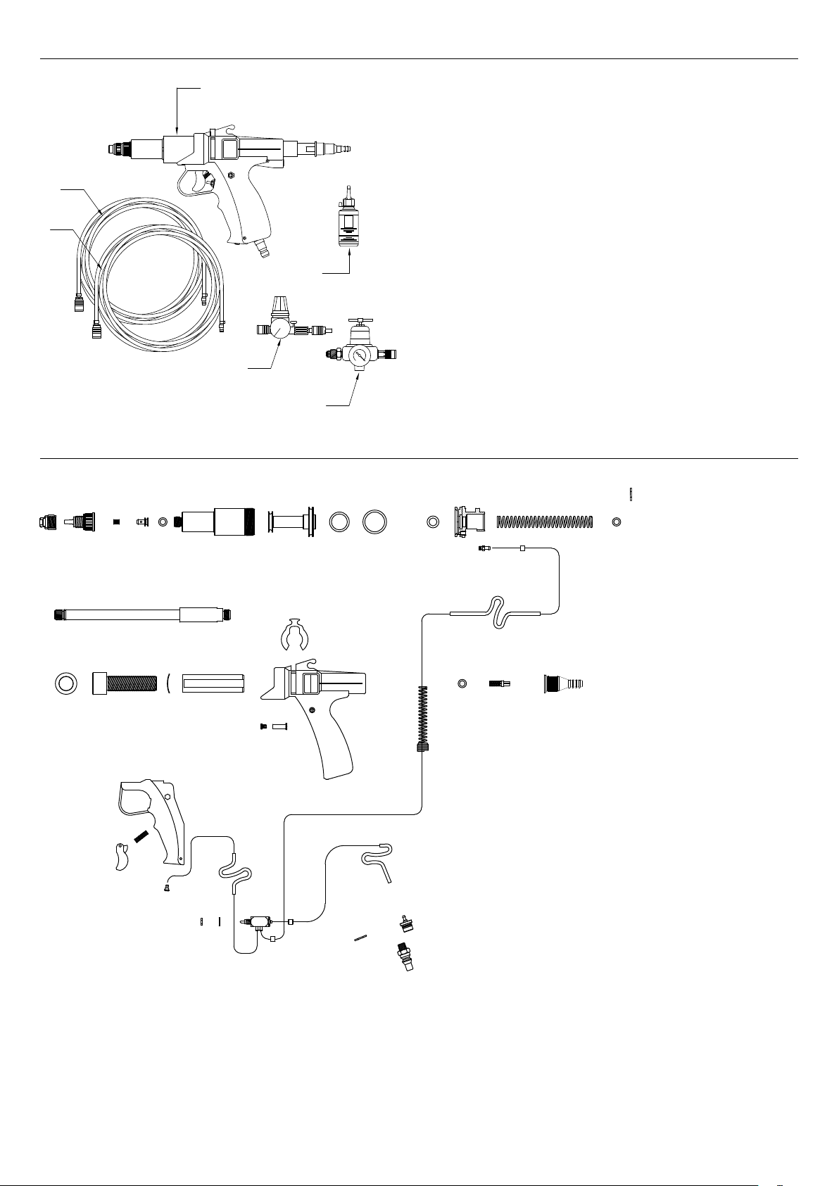
SECTION 1: INJECTOR PARTS IDENTIFICATION AND SCHEMATIC DIAGRAMS
Schematic Diagram No 1: NJ Phillips15ml Powered Injector. 4
SECTION 2: SETTING UP THE INJECTOR READY FOR USE
Schematic Diagram No 2: Handpiece Component Breakdown. 4
1. Handpiece Injectable Products 5
2. Injector Operated by LP-GAS Portable or Processor 5
Schematic Diagram No 3: Injector setup for operation by LP-Gas Portable or Processor 6
3. Injector Operated by Compressed Air 7
Schematic Diagram No 4: Injector setup for operation by Compressed Air 6
SECTION 3: CARE AND MAINTENANCE OF INJECTOR 8
SECTION 4: TROUBLE SHOOTING GUIDE 9
SECTION 5: WARRANTY AND SERVICE 10
PAGE 4
35
30
34
33
28
27
29
36
32
36
40
38
31
188
17 19
18
4
15
22 23
21
20
23567
39
16 26
37
24 25
11
35
9
36
10 12 13
14
1
2
6
3
4
5
SECTION 1: INJECTOR PARTS IDENTIFICATION AND SCHEMATIC DIAGRAMS
Schematic Diagram No 1: NJ Phillips15ml Powered Injector.
SECTION 2: SETTING UP THE INJECTOR READY FOR USE
Schematic Diagram No 2: Handpiece Component Breakdown.
1. NEEDLE NUT
2. NEEDLE MOUNT
3. VALVE SEAT
4. FRONT VALVE RETAINER
5. SEAL RING
6. CYLINDER
7. PISTON
8. SEAL RING
9. SEAL RING
10. HANDLE PLUG
11. AIR FITTING
12. RETURN SPRING
13. CIRCLIP
14. SEAL RING
15. PUSHROD
16. SPACER BUSH
1. 15ml Powered Injector
2. 10 metre Air Line
3. 10 metre Gas Line
4. Air Regulator Assembly
5. Gas Regulator Assembly
6. NJ Phillips Lubricant
17. DOSE ADJUSTOR - THREADED
18. WAVE WASHER
19. DOSE ADJUSTOR SLEEVE
20. HANDLE CLIP
21. HANDLE
22. LOCK SCREW
23. HANDLE LOCK SLEEVE
24. SEAL RING
25. REAR VALVE
26. INLET FITTING
27. TRIGGER
28. TRIGGER RETURN SPRING
29. LEVER
30. EXHAUST ADAPTOR
31. AIR TUBE - EXHAUST
32. TRIGGER VALVE ASSEMBLY
33. WASHER - TRIGGER
34. TRIGGER VALVE LOCK NUT
35. AIR TUBE - INLET
36. AIR TUBE RETAINER
37. ANTI KINK SPRING
38. CIRCLIP
39. ADAPTOR - AIR FITTING
40. MALE GAS FITTING

PAGE 5
1. HANDPIECE INJECTABLE PRODUCTS
Refer schematic diagram No 2: Handpiece component
breakdown.
Before commencing, attention must be given to following
the chemical manufacturer’s safety instructions at all times
and gloves must be worn at all times to prevent chemicals
contacting the hands. Please ensure the handpiece and
feed tube have been thoroughly cleaned and ushed out as
covered by section III of this booklet, care and maintenance
of injector.
a. The injector has been supplied with a 15ml injectable
cylinder.
Please refer to the pharmaceutical manufacturer’s
administration instructions for selection of needle to be
used.
b. Fit the selected needle as specied in the pharmaceuticals
manufacturer’s administration instructions, to the luer
tting (diag. 2 -1).
c. Using pliers and 9/16” AF open ended spanner, unscrew
the inlet adaptor (diag. 2 - 26) from the handpiece
and check that the inlet valve and spring (diag. 2 -
25) are clean, and facing in the direction as shown in
the handpiece diagram. Re-t the inlet adaptor to the
handpiece and hand tighten with pliers and open ended
spanner.
dThe handpiece is now set up ready for connection
to the draw off system for the injectable treatment of
livestock.
2. INJECTOR OPERATED BY LP-GAS PORTABLE
OR PROCESSOR
Refer Schematic Diagram No 3: Applicator setup for
operation by LP-Gas Portable or Processor.
WARNING: You must not t or use faulty, poor quality
or incompatible associated parts or components, and in
particular the use of a gas regulator and valve assembly
other than those components supplied with the product.
You must not repair, alter or modify the product, other
than those carried out by NJ Phillips Pty Limited or it’s
authorised agent, and in particular interference with or
modication in any way to the injector gas tube or other
components relating to the use of LP gas to operate the
product. Any occurence of these issues will VOID the
warranty. See warranty statement page 10.
a. Fill the gas cylinder with liquid propane gas (LPG).
WARNING: Gas cylinders must only be lled by
authorised lling agents.
NOTE: DO NOT OVERFILL GAS CYLINDER: It is
important not to overll the gas cylinder as liquid gas
may enter the injector and freeze the trigger valve. When
lling, shut off the lling exhaust valve as soon as the
rst cloudy vapour is observed coming from the valve.
Do not ll until liquid gas is pouring out and freezing up.
If liquid gas enters the gas tube, release the regulator
tting on the gas tube, and the liquid will vaporise.
b. Connect the gas regulator and valve assembly to the gas
cylinder as covered by the instruction leaet supplied
with the regulator and valve assembly, and detailed in
sections 1 to 5 of that procedure.
c. Connect the gas tube to both the injector and the outlet
port on the regulator, and hand tighten.
Set the gas operating pressure at 414 to 550 Kpa (60-80
psi) on the pressure gauge as covered by sections 6 and
7 in the instruction leaet supplied with the regulator and
valve assembly.
NOTE: The gas pressure may require adjustment by the
regulator within the specied limits to achieve satisfactory
delivery of injectable products, and may vary depending
on climatic conditions, use of the injectable product in the
upright or inverted position, or the type of needle used.
d. The injector is now set up ready for the vaccine bottle to
be connected to the appropriate feed tube and the feed
tube to the injector.
e. Connect the one end of the feed tube to the inlet adaptor
on the applicator and the other to the draw off system.
Ensure the feed tube springs are securely screwed over
the feed tube in an anticlockwise direction. This will
prevent the feed tube kinking.
i. NOTE: The injector must only be used with the gas
cylinder placed in the upright or vertical position, so
that gas and NOT liquid LPG passes through the
valve on the gas tube. Otherwise the liquid LPG
will freeze up the valve and the injector will cease
to operate. In this case, release the regulator tting
on the gas tube for the liquid LPG to vaporise, then
re-tighten.
ii. It is essential, to prevent injury to the user, that you
refer to the WARNING STATEMENTS relating to
the use of the injector when operated by LP gas, as
covered in the Powermaster handbook page 2, and
the instruction leaet supplied with the regulator and
valve assembly, instructions for connection of gas
regulator to LP gas cylinder.
f. To prime the injector set the dose at 15ml and with the
instrument held vertically with the needle pointed upwards
depress the trigger a number of times until the injectable
product is expelled from the needle in an unbroken
stream and all air bubbles have been eliminated from
the cylinder.
g. To Set Required Dose:
iDose levels and application of the injectable product
must be set in accordance with the pharmaceutical
manufacturer’s administration instructions.
ii. Turn the dose adjustor in an anticlockwise direction to
decrease dose, and a clockwise direction to increase
the dose, as indicated by graduations on the dose
adjustor sleeve.
iii. To be sure of complete accuracy, the dose must be
checked with a calibrated measuring cylinder.
iv. Cylinder ll rate and delivery pressure can be varied
with adjustment to the gas pressure on the regulator
between 414 to 550 Kpa (60 - 80 psi).
The minimum pressure should be used to achieve
acceptable lling rate and delivery speed.
h. The injector is now set up ready for the injectable
treatment of livestock.
i. WARNING: Care must be taken to ensure the liquid
does NOT come into contact with any part of the
operators body. Chemicals may injure the operator.
WARNING: At the close of each days work, or
on completion of treatment of livestock, to avoid
possible unsafe or hazardous situations, the
regulator valve must be fully closed by turning in a
clockwise direction, as indicated

PAGE 6
Schematic Diagram No 3: Injector setup for operation by LP-Gas Portable or Processor
TO AIR COMPRESSOR
10 METRE AIR LINE
TO INJECTABLE
CHEMICAL. VIA
PORTABLE OR
GAS LINE
TO INJECTABLE
CHEMICAL. VIA
TO GAS CYLINDER
PROCESSOR
FEED TUBE
FEED TUBE
Schematic Diagram No 4: Injector setup for operation by Compressed Air
TO AIR COMPRESSOR
10 METRE AIR LINE
TO INJECTABLE
CHEMICAL. VIA
PORTABLE OR
GAS LINE
TO INJECTABLE
CHEMICAL. VIA
TO GAS CYLINDER
PROCESSOR
FEED TUBE
FEED TUBE

PAGE 7
3. APPLICATOR OPERATED BY COMPRESSED AIR
Refer Schematic Diagram No 4 page 6: Applicator setup
for operation by compressed air.
When compressed air is used to operate the injector for the
treatment of livestock, to prevent moisture and or other foreign
matter entering the applicator and affecting the operation of the
trigger valve system, the manufacturer strongly recommends
that an approved lter/lubricator suitable for compressed
air systems, MUST be installed in the compressed air line
connected to the regulator and applicator. Otherwise, moisture
and or foreign matter will enter the trigger valve system
(diag. 2-32) of the applicator, which will cease to operate in
a satisfactory manner. Warranty claims will not be accepted
for damage caused by moisture or foreign matter entering the
trigger valve system due to the installation of an unapproved
lter/lubricator.
The manufacturer recommends 10mm inside diameter
compressed air hose and suitable 10mm ttings should be
used for connection of the applicator pressure regulator to
the compressed air supply hose, and the compressor unit
supplying the compressed air to the applicator be set to
operate at a maximum of 690 Kpa (100 psi).
a. Connect the regulator assembly to one end of the
compressed air hose by a suitable hose clamp, and
connect an approved compressed air in line lter/lubricator
to the other end of the compressed air hose at the outlet
from the air compressor.
b. Connect the 10m air line (diag. 1-2) to both the applicator
and the outlet port on the regulator and hand tighten.
c. Turn on the air compressor, and when the air pressure
has reached its operating level (max 690 Kpa - 100 psi),
fully open the brass inlet valve on the regulator by turning
in an anticlockwise direction.
d. Set the air operating pressure of the applicator at 414 to
550 Kpa (60 - 80 psi) on the pressure gauge by turning the
black control knob on the regulator in a clockwise direction
to increase pressure. If the pressure is too high, reduce
by turning the black control knob in an anticlockwise
direction, operate the applicator a few times, and adjust
for optimal pressure setting. When the optimal air pressure
is achieved, fasten the lock nut on the black control knob
screw against the regulator body with a 12mm AF open
ended spanner.
NOTE: The air pressure may require adjustment by the
regulator within the specied limits to achieve satisfactory
delivery of injectable products, and may vary depending
on climatic conditions, use of the injectable product in the
upright or inverted position, or the type of needle used.
e. The injector is now set up ready for the vaccine bottle to
be connected to the appropriate feed tube and the feed
tube to the injector.
f.Connect the one end of the feed tube to the inlet adaptor
on the applicator and the other to the draw off system.
Ensure the feed tube springs are securely screwed over
the feed tube in an anticlockwise direction. This will
prevent the feed tube kinking.
g. To prime the injector set the dose at 15ml and with the
instrument held vertically with the needle pointed upwards
depress the trigger a number of times until the injectable
product is expelled from the needle in an unbroken
stream and all air bubbles have been eliminated from the
cylinder.
h. To Set Required Dose:
i. Dose levels and application of the pour-on product
must be set in accordance with the pharmaceutical
manufacturer’s administration instructions.
ii. Turn the dose adjustor (diag. 2-17) in an anticlockwise
direction to decrease dose, and a clockwise direction
to increase the dose, as indicated by graduations on
the push rod (diag. 2-15).
iii. To be sure of complete accuracy, the dose should be
checked with a calibrated measuring cylinder.
iv. Cylinder ll rate and delivery pressure can be varied
with adjustment to the compressed air pressure on
the regulator between 414 to 550 Kpa (60 - 80 psi).
The minimum compressed air pressure should be used to
achieve acceptable lling rate and delivery speed.
i. The applicator is now set up ready for the injectable
treatment of livestock.
j. WARNING: Care must be taken to ensure the liquid
does NOT come into contact with any part of the
operators body. Chemicals may injure the operator.
WARNING: At the close of each days work, or on
completion of the pour-on treatment of livestock,
to avoid possible unsafe or hazardous situations,
the regulator valve must be fully closed by turning
in a clockwise direction, as indicated by arrow on
the valve, and turn off the air compressor. Failure
to do this may result in excess pressure build up in
the regulator causing it to fail which may injure the
operator.

PAGE 8
To ensure continued high performance from the injector, attention to cleanliness is essential, both for the protection of the
user and livestock. On completion of each use of the injector the injector and feed tube MUST be thoroughly cleaned in
accordance with the following procedure.
WARNING: For the protection of the operator, gloves must be worn at all times whilst carrying out
this procedure. Also avoid skin, body contact or inhalation of chemicals, which may cause injury to
the health of the operator.
1. Leave the power source connected to the instrument.
2. Place the injector feed tube into a clean container with a mix of approximately 1 litre of warm water and 0.5ml of non-
corrosive detergent.
3. Set dose of injector to 15ml and pump the solution through the injector and feed tube by depressing trigger a number
of times until the injector cylinder and feed tube are clean.
4. Hand wash exterior of injector, feed tube and springs with a soft brush.
5. Rinse the injector and feed tube by ushing through with clean water and pump dry by depressing trigger a number
of times.
6. Wipe injector, feed tube and springs dry, disconnect the feed tube from injector and place aside.
7. Using the NJ Phillips Lubricant supplied in the tool box, immerse the injector inlet tting into a small clean container
of Lubricant and draw a small quantity of Lubricant into the cylinder by depressing the trigger several times.
Fully close regulator valve by turning in a clockwise direction, disconnect the air or gas tube from both the regulator
and injector, and place aside.
8. Switch off the air compressor or gas cylinder and release pressure in hose. Disconnect the tting adaptor from the
snap-in barb coupling on the hose. Disconnect the tting adaptor from the regulator and valve assembly and place
both parts into toolbox.
9.
a. Remove the cylinder assembly from the injector handpiece by unscrewing in an anticlockwise direction, taking
care not to damage the seal rings on piston and place cylinder assembly aside.
b. Check seal rings (diag. 2-8) for any sign of wear or damage and replace if necessary.
c. Take the cylinder assembly, check the inside is thoroughly clean, otherwise wash out with a mixture of warm
water and detergent, rinse with clean water and wipe dry. Lubricate inside of the cylinder, piston rings, and push
rod shaft behind the piston, with a small quantity of NJ Phillips Lubricant . Carefully place the cylinder over the
piston and screw into handle in a clockwise direction and hand tighten. Place the injector with cylinder attached,
into tray of toolbox.
SECTION 3: CARE AND MAINTENANCE OF INJECTOR

PAGE 9
SECTION 4: TROUBLE SHOOTING GUIDE
CORRECTIVE ACTION - CHECK POINTSPROBLEM PROBABLE CAUSE
Injector lacks power or not
functioning
Bottle Gas. Check:
i. gas
ii. No leaks in gas hose.
iii. Check gas bottle is full and set to 414 to
550kpa (60-80psi)
Inadequate gas pressure. Reset pressure on regulator. Wind black knob
fully out and then wind in until pressure on gauge
reaches 414 to 550 kpa (60-80 psi).
Regulator outlet port and
ttings not rmly attached to
the regulator.
Ensure outlet port and brass ttings are rmly
screwed into regulator.
Injector leaking Fault in tube connections
from pressure regulator to
trigger on injector
Fully close regulator valve, disconnect injector from
regulator and return injector to stockist or local
distributor for service.
Injector will not deliver full
dose
Injector not primed or dose
not set correctly
Prime the injector and set dose as covered by
instructions .
Inlet valve and seal ring not
sealing, caused by foreign
matter lodged under the inlet
valve
Remove the inlet adaptor and inlet valve from
injector, clean with water and replace in injector.
Foreign matter lodged in
the delivery valve assembly
or a blockage in the needle
mount.
Remove needle mount and delivery valve
assembly from the injector, clean the delivery valve
assembly, and re-assemble .
Slow injector (ll and/or
delivery rate of product)
Incorrect pressure setting on
regulator (diag 1-4 or 5)
Check and adjust regulator pressure to operate
injector between 414 to 550 kpa (60 – 80 psi).
Kinking or restriction of the
feed tube
Remove the restriction or re-position the feed tube
to avoid kinking.
Piston seal rings are dry or
have not been lubricated
Remove cylinder from handpiece and lubricate the
piston seal rings with NJ Phillips Lubricant.
Spitting of product from
needle or air being drawn
into the cylinder from
the needle mount end of
injector
Foreign matter lodged in the
delivery valve and assembly.
Remove needle mount and delivery valve
assembly, clean valve by rinsing and wiping with a
soft cloth. Clean valve and re-assemble.
1.
2.
3.
4.
5.
Air compressor. Check:
i. Compressor supply adequate air pressure.
ii. No leaks in air hose.
PAGE 10
Scope of this warranty
This warranty entitles you to repairs or replacement (at no charge) of any parts
of the NJ Phillips 15ml powered injector (“Product”) found to be defective in
materials or workmanship. Repair or replacement is at the option of NJ Phillips
Pty Limited (“Company”) or its authorised agent. This warranty is in addition
to any rights and remedies extended to the owner under applicable laws, and
is not intended to negate or restrict such rights and remedies except where it
is competent to do so.
What is not covered by this warranty
Repair or replacement under this warranty is not available for faults or failure
due to:
• ordinary wear and tear;
• accident, contamination, misuse, neglect, abuse or tampering;
• incorrect installation or maintenance;
• failure to follow the Company’s warnings, instructions, and recommendations
for safe and effective use;
• the tting or use of faulty, poor quality or incompatible associated parts or
components, and in particular the use of a gas regulator and valve assembly
and/or gas cylinder other than those component parts supplied with the
Product;
• use of the injector other than for its designed purpose;
• use of the injector with any product other than products specically
recommended by your stockist/local distributor or NJ Phillips Pty Limited.
• repairs, alterations or modications carried out other than by the Company
or its authorised agent; or
• any other cause occurring after the Product left the Company’s, stockist’s
or local distributor’s control.
Subject to the operation of any laws to the contrary, this warranty does not
cover:
• the costs of travelling or transportation of the Product or parts to and/or
from the Company or its authorised agent;
• loss of the injector or parts while in transit to or from the Company or its
authorised agent; or
• personal injury, property damage, or economic and consequential loss or
damage, howsoever caused.
The Company and its authorised agents reserve the right to charge their
reasonable costs in investigating and correcting faults and failure caused other
than by defects in materials or workmanship.
How to claim under this warranty
If service is necessary, contact the Company or an authorised agent, and
provide details of the alphanumeric batch code number located on the handle
of the Product, and the date of purchase.
SECTION 5: WARRANTY AND SERVICE
QL520-R3
NJ PHILLIPS Pty Limited ABN 36 000 082 002
44 Gindurra Road Somersby NSW 2250, Australia
Locked Bag 8 Gosford NSW 2250, Australia.
Thank you for purchasing this NJ Phillips Pty Limited precision
instrument. Norman Phillips founded the Phillips reputation on
reliability, accuracy and innovation in 1931. It is by not deviating
from these original ethics that NJ Phillips Pty Limited is able to
guarantee this instrument is not only the best you can buy today,
but that tomorrow’s NJ Phillips instrument will be even better.
N. John Phillips
EXECUTIVE CHAIRMAN
Table of contents
Other NJ PHILLIPS Laboratory Equipment manuals


