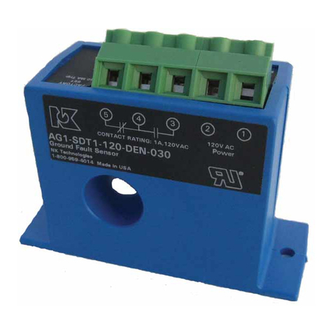
NK TECHNOLOGIES AGV Series User manual

INSTRUCTIONS
1. Pass all current carrying conductors include neutral
return not ground return through sensor window.
2. Mount the sensor to a surface if needed.
3. Connect output & power wiring to unit.
A. Use 22-14 AWG copper wires rated for 75°C mini-
mum.
B. Make sure power and load matches those shown on
the senors’ label.
C. Set the desired trip point using the slide switch to
choose 30, 50, or 100 mA setting.
4. Energize the monitored circuit. Add delay before
the output changes state as required by turning pot
clockwise, arrow pointing to the seconds added.
5. Test
A. Pressing the “TEST” button tests the sensor’s
internal circuits. CAUTION: The output and any
connected loads will switch! The LED shows red
when a fault is detected or test button is pressed.
B. For latching output models (-LA), momentarily
shorting between the “reset” terminals will release
the latched output contact. Do not apply voltage to
the reset terminals.
AGV 3 - SDT - 24U - LA - TR3
Model Number KeySpecifi cations
Know Your Power
Quick “How To” Guide
Power Supply Notes
AGV Series
Ground Fault Sensors
For VFD Driven Loads
490061007 Rev 1
Output Type
SDT - Single Pole, Double Throw
(Form C SPDT Relay)
Power Supply
24U - 24 VAC/DC
120 - 120 VAC
Setpoint Range
3 - Tri-Set, 30, 50, & 100 mA, Slide Switch
Select
AGV Series Ground Fault
Output
DEN - Normally De-energized
ENE - Normally Energized
LA - Latching
Power Supply 24 VAC/DC (19-24V)
120 VAC (90-130V)
Power Consumption 2.4 VA max. (24V power)
3 VA max. (120V Power)
Trip point Range 30, 50 & 100 mA, Switch Select
Voltage Range Up to 600 VAC (Monitored Circuit)
Frequency Range 12-398Hz (Monitored Circuit)
Relay Output SPDT 1A@120 VAC, 2A@30 VDC
Frequency of Monitored Circuit Response Time
<17 Hz <140 ms
17-32 Hz <75 ms
>32 Hz <45 ms
Time Delay 0-10 seconds plus response time
Isolation Voltage 1240 VAC, tested to 5KV
Sensor Power Indication Green LED = Power untripped
Output Tripped Status Red LED = Output tripped
Dimensions 2.91”Hx3.86”Wx1.45”D
(73.9x98.0x36.8 mm)
Aperture 0.75” (19.1 mm) inside diameter
Case UL 94V-0 Flammability Rated
Environmental -4 to 122°F (-20 to 50°C)
System Grounding
3511 Charter Park Drive, San Jose, CA 95136
Phone: 800-959-4014 or 408-871-7510
Fax: 408-871-7515
[email protected], www.nktechnologies.com
Know Your Power
Other NK Technologies Products Include:
AC & DC Current Transducers
AC & DC Current Operated Switches
1 & 3Power Transducers
Current & Potential Transformers (CTs&PTs)
All low-current Ground-Fault Sensors are sensitive devices
that require reasonable care in system design to avoid false
trips caused by high electrical noise levels. Keep in mind
that the best way to reduce noise in a system is to suppress
it at its source.
1. Keep the sensor power isolated from noisy circuits.
2. Do not power the sensor with the same circuit that switches
contactors or other high current, inductive loads.
Good design practice and code require that all AC power
systems be grounded. AGV Series sensors are designed to
work on grounded AC power systems. They will not operate
properly on ungrounded systems.
Setpoint
TR3 - Tri-Set, 30/50/100 mA
Switch Select

Description
Operation
Principal of Operation
Under normal conditions, the current in one wire of a two
wire load is equal in strength but opposite in direction. The
two wires together create cancel magnetic fi elds, a condi-
tion known as “Zero Sum Current”. If any current leaks to
ground (Ground Fault), the two currents become unbalanced
and there is a net resulting magnetic fi eld. The AGV sensor
detects this minute fi eld and changes the output state. This
concept extends to three phase systems such as 3 wire Delta
(grounded) and also 3 or 4 wire Wye.
AGV Series sensors work in the same environment as mo-
tors, contactors, heaters, pull-boxes, and other electrical
enclosures. They can be mounted in any position or hung
directly on wires with a wire tie. Just leave at least one inch
distance between sensor and other magnetic devices. Run
all current carrying conductors through the opening in the
sensor. (See “Principal of Operation”) Be Sure all wires
in a three phase system are oriented so current fl ows in the
same direction.
Installation & Wiring
AGV Series sensors monitor all current carrying wires in
single or three phase systems to detect ground faults. They
provide a contact output that can operate relays, contactors
or signal automation systems. The design goal is to provide
a reliable detection with less spurious tripping.
Wiring to unit
Use 22-14 AWG copper wire and tighten terminals to 5-7
inch-pounds torque. See Diagram.
Power
Connect power wiring to Terminals 1 & 2. Be sure that
the power supply matches the power supply limits on the
sensor label.
Output
Connect output wiring to Terminals 3&4 (NC) or 4&5 (NO).
Reset Switch (Latching Models) Terminals 6&7
Momentary Reset
The sensor will not work properly if the reset terminals are
closed (shorted) continuously. Only close the reset terminals
momentarily.
Parallel Reset Connection
Multiple sensors may be connected to the same reset switch
in parallel. Only the sensors that have detected a fault and
have latched will be reset. A sensor will not reset unless the
fault has dropped below setpoint.
AGV Series Latching Ground fault sensors operate in one of
two states: Reset or Latched. If control power is removed,
the sensor remains in it’s last state (latched or reset).
Reset
The sensor has not detected a fault and the output is in the
“normal” position.
Latched
Upon detecting a fault or when the TEST switch is pressed,
the output will switch (NO 4&5 closes and NC 3&4 opens),
and “latches”. The output will remain latched until the ground
fault is removed and the output is reset by a momentary dry
contact on Terminals 6 &7.
With DEN type models, the NO contact (4&5) closes on a
fault and the NC (3&4) contact opens.
With ENE type models, the NO contact (4&5) closes when
power is applied to the sensor, opens on a fault and the NC
(3&4) contact opens when power is applied, and closes on
a fault. The sensor contacts also revert to “shelf state” when
power is removed from the ENE type models.
Testing
To test operation, gently press the TEST button. This
simulates a fault and tests the internal switching circuits.
After the test is complete, reset the sensor with a momentary
dry contact on Terminals 6 & 7. CAUTION: Any circuit
connected to the sensor will be operated. Do not apply
voltage to the reset terminals.
Monitored Circuit
Feed the wires carrying the monitored circuit current through
the sensing aperture. The same sensor can monitor a single
phase (hot and neutral), two phases (two hot) or three phase
load up to 600 VAC. If the monitored load uses the neutral,
it must pass through the aperture. The bond or ground wire
should never be included.
Output table
Normally Energized Models( -ENE Option)
Protection from faults and control power loss.
Control Power Applied
No Power No Fault Fault
N.C. Normally Closed closed closed open
N.O. Normally Open open open closed
Control Power Applied
No Power No Fault Fault
N.C. Normally Closed closed open closed
N.O. Normally Open open closed open
Latching Models (-LA Option) from factory power up initially in the
reset (normal) mode. If there is a fault condition or the test button is
pushed, the output contacts will change state and latch. The output will
remain latched regardless of whether the fault is cleared or control power
is removed. To reset the output apply a momentary contact across “reset”
terminals.
Connect a momentary dry contact to the reset terminals
(6&7). Limit wire run to 200’ of 18 AWG or larger wire.
Normally De-energized Models( -DEN Option)
Protection from faults.
490061007 REV 1

Typical Installations
The AGV series ground fault detector was purposely
designed to allow the protection of a load driven with
a variable frequency drive to sense a fault to earth low
enough to keep the equipment from being damaged but
also to protect the workers using the equipment from
electrocution. They will also work in applications where
the frequency is stable.
When the auto-reset type sensor is installed on the load
side of a drive, between the motor and the controller the
sensor contact which is open when the sensor is pow-
ered (NO 4&5 with -DEN contact action, NC 3&4 with
-ENE contact action) is most often used to energize the
operating solenoid of a shunt trip breaker. The draw-
ing to the left illustrates a way these two components
connect to work as a circuit disconnect. Once a fault is
detected and the breaker has opened to de-energize the
monitored circuit the fault goes away and the sensor re-
sets to the original condition. The breaker handle acts as
the reset to re-energize the load after the fault has been
alleviated.
When the latching sensor is installed on the load side of
a drive, between the motor and the controller the sen-
sor contact the normally closed contact (3&4) is most
often used to energize the operating coil of a contac-
tor. The drawing to the left illustrates a way these two
components connect to work as a circuit disconnect.
Once a fault is detected and the sensor contact opens to
de-energize the contactor coil, which opens the contac-
tor contacts. The contacts stay open until an externally
mounted momentary pushbutton is closed across termi-
nals 6 and 7. This resets the sensor output contacts so
the monitored motor can be restarted.
490061007 REV 1
Trouble Shooting
1. During motor start, there may be an exces-
sive amount of current loss due to capacitance
leakage. This is shown as less current being
returned to the source in the same manner as
loss to ground. Field conditions will vary.
Adjust the time delay to allow the sensor output
to remain in the “no fault” condition during
this period of current loss.
2. Longer runs of submersible pump cable or
heat trace cable may create conditions with
capacitance leakage between the two parallel
conductors. This occurs constantly and the time
delay will not keep the sensor from tripping.
The solution is to raise the trip point.
3. Only the current carrying conductors pass
through the sensing aperture. If using shielded
cable, pass the shield through the sensor and
then loop back to bond to earth on the line side
of the sensor.
4. VFDs can produce quantities of electromag-
netic noise, so it is recommended to allow as
much space between the drive and the sensor.
This condition varies greatly between drive
manufacturers and drive size, so spacing is a
fi eld installation variant.
5. Latching output sensors are reset by closing
a contact between terminals 6 and 7. While
usually accomplished with a pushbutton, a solid
state transistor can also be used. The sensor
shows a (+) and (-) on the label, and this is only
important if a solid state switching arrangement
is used. No external voltage source is used.
The AGV sensor can be set to trip with a fault detected
of 30, 50, or 100 mA. There is also a 0-10 second time
delay which is adjusted by turning the potentiometer
from the zero clockwise to 10 seconds as indicated on
the label.
12345
AC
DC
M
Shunt Trip
Breaker
Power For
Shunt Trip
Internal
Contact
Sensor
Power
Output
Contacts
Other NK TECHNOLOGIES Accessories manuals
Popular Accessories manuals by other brands

Sulzer
Sulzer ABS MD 127 Installation and user manual
Leviton
Leviton 31A00-8 installation instructions
wamovo
wamovo KB35 instructions

Vega
Vega VEGAPULS 21 operating instructions

Olimpia splendid
Olimpia splendid Astomi 80 Instructions for installation, use and maintenance

ADT
ADT Pulse Interactive Solutions DBC845 installation guide


