NK TECHNOLOGIES AG1 Series User manual
INSTRUCTIONS
1. Run all current carrying conductors
through sensor window
A. Use an auxiliary CT if conductors do not fit. Con-
sult Factory for CT selection.
2. Mount the sensor to a surface if needed.
3. Connect output & power wiring.
A. Use up to 14 AWG copper wires.
B. Make sure load matches the output shown on the
sensors’ label.
•Sensors labeled “xxAC” will only switch AC.
•Sensors labeled “xxDC” will only switch DC.
C. Make sure power supply matches the power input
shown on the label.
4. Test
A. Pressing the “TEST” button tests the sensors inter-
nal circuits. CAUTION: The output and any con-
nected loads will switch!
AG1-NCAC-120 -FS - 005
Model Number KeySpecifications
Quick “How To” Guide
Power Supply Notes
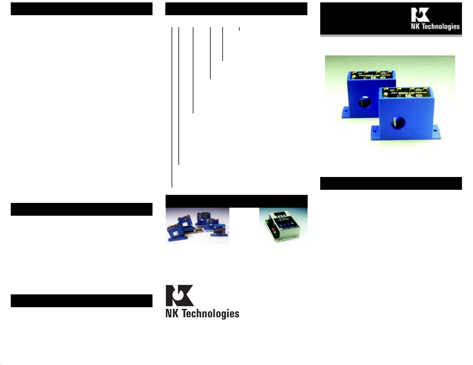
AG 1, 2 & 3 SERIES
Ground Fault Sensors
Auto-Reset
Output Type
NCAC Normally Closed 1A @ 240 VAC
NOAC Normally Open 1A @ 240 VAC
NCDC Normally Closed 0.15A @ 30 VDC
NODC Normally Open 0.15A @ 30 VDC
NCR Normally Closed, 0.5A @ 120 VAC, 0.25A
@ 240 VAC, 2A @ 30 VDC
NOR Normally Open, 0.5A @ 120 VAC, 0.25A @
240 VAC, 2A @ 30 VDC
Power Supply
24U 24 VAC/DC
120 120 VAC
240 132-264 VAC
Setpoint Range
1 5-100mA, Adjustable
2 80-950mA, Adjustable
3 Tri-Set, 5, 10 & 30 mA, Jumper Select
AG Series Ground Fault Sensor
Setpoint Range AG1 Series: 5-100mA Field Adjustable
AG2 Series: 80-950mA Field Adjustable
AG3 Series: Tri-Set, 5, 10 & 30 mA, Jumper
Select
Voltage Range Up to 1,500 VAC (Monitored Circuit)
Frequency Range 50-400Hz (Monitored Circuit)
OutputOptions (See Product Label)
Solid State AC Switch 1A @ 240 VAC (2A for 10 Min)
Solid State DC Switch 0.15A 30 VDC (500mA
momentary)
Relay Output 0.5A @ 120 VAC, 0.25A @ 240
VAC, 2A @ 30 VDC
Response Time 150 mS @ 5% above setpoint.
100 mS @ 50% above setpoint.
Power Supply Operates from 55-110% of nominal voltage
NominalVoltages 120, 240 VAC (50-400 Hz)
Green LED=Power
Optional Power 24VAC or 24 VDC Operates +/- 20%
Power Consumption 2.5 Watts
Dimensions 2.5"H x 2.8"W x 1.5"D, (64x71x38mm),
aperture 0.75" (19mm) dia. (See Diagram)
Case UL 94V-O Flammability Rated
Environmental 5 to158 DegF (-15 to 70 DegC), 0-95% RH,
Non Condensing
Listings UL 1053, Class 1 Recognized, CE Certified
(Not all option combinations are recognized.
See product label)
System Grounding
Know Your Power
Other NK Technologies Products Include:
AC & DC Current Transducers
AC & DC Current Operated Switches
1φ& 3φPower Transducers
Current & Potential Transformers (CTs&PTs)
All low-current Ground-Fault Sensors are sensitive devices
that require reasonable care in system design to avoid false
tripscausedbyhighelectricalnoiselevels. Keepinmindthat
the best way to reduce noise in a system is to suppress it at its
source.
1. Keep the sensor power isolated from noisy circuits.
2. Do not power the sensor with the same circuit that
switchescontactorsorotherhighcurrent,inductiveloads.
Good design practice and code require that all AC power
systems be grounded. AG Series sensors are designed to
workongroundedACpowersystems. Theymaynotoperate
properly on ungrounded systems.
Setpoint
005 to 950 Factory Adjusted
Setpoint in mA (specify
when ordering)
TR3 Tri-Set, 5, 10 & 30 mA,
Jumper Select
Options
FS Normally Energized
NF Normally De-energized

Normally Energized Models (-FS) Detects Ground Faults and loss of control power
CONTROL POWER APPLIED
NO POWER No Fault Fault Detected
Output Style Output LED Output LED Output LED
N.C. Normally Closed CLOSED Off OPEN ON CLOSED OFF
N.O. Normally Open OPEN Off CLOSED ON OPEN OFF
Normally De-Energized Models (-NF) Detects Ground Faults only.
CONTROL POWER APPLIED
NO POWER No Fault Fault Detected
Output Style Output LED Output LED Output LED
N.C. Normally Closed CLOSED Off CLOSED OFF OPEN ON
N.O. Normally Open OPEN Off OPEN OFF CLOSED ON
Description
Operation
Principal of Operation
AG Series sensors work in the same environment as mo-
tors, contactors, heaters, pull-boxes, and other electrical en-
closures. They can be mounted in any position or hung
directly on wires with a wire tie. Just leave at least one inch
distance between sensor and other magnetic devices.
Run all current carrying conductors through the sensor
apeture in the same direction. (See “Principal of Opera-
tion)
Connect power wiring to the sensor. Be sure that the power
supply matches the power rating on the sensor label. Use
up to 14 AWG copper wire and tighten terminals to 7 inch-
pounds torque.
Installation & Wiring
Connect output wiring to the sensor. Be sure that the out-
put load is less than or equal to than the output rating on
the sensor label. Use up to 14 AWG copper wire and tighten
terminals to 7 inch-pounds torque.
Totestoperation,gentlypressthe
TEST button. This simulates a
faultandtests theinternalswitch-
ing circuits.You should observe
the following operation.
CAUTION: Any circuit con-
nected to the sensor will be op-
erated.
Power Output
G
X
Control Power
Match Sensor Rating
(See Label)
Setpoint Adjust
Factory calibrated &
covered. Remove cover,
adjust & relabel if required.
Load
Contactor, Relay, Shunt Trip Breaker, etc.
Do not exceed Rating (See Label)
Output Power
Match Sensor Rating
(See Label)
TEST
(+)
(_)
For DC Output Version
ObservePolarity
Setpoint Adjustment
AG1 & AG2 Series sensors are factory calibrated to trip at
the setpoint specified at the time order. We highly recom-
mend leaving this factory calibrated setpoint alone. If you
must change the factory setpoint, follow these steps:
A. Setup
Connectcontrolpowerandoutputcircuits. Runaconductor
through the aperture with current equal to your desired set
point .
B. Adjust Setpoint to Maximum
Remove the Setpoint Cover. Turn the adjustment pot 4
revolutionsCCW(CounterClockwise)tothemaximum (least
sensitive) setpoint. The Status LED should be OFF. The
adjustment pothasaslipclutchsoyoucannotfeelordamage
the end point.
C. Dial in new Setpoint
Turn the pot slowly CW (Clockwise) until the LED turns
ON. The sensor is now adjusted to trip at the current that is
passing through the aperture. Reset the sensor.
D. Relabel Sensor
Relabel the sensor with the new setpoint. Use a label maker
or tape with a permanent marker.
AG3 Move the jumper to the desired setpoint as shown on
the label.
Under normal conditions, the current in one wire of a two
wire load is equal in strength but opposite in sign to the
current in the other wire. The two wires create magnetic
fields that cancel, a condition known as “Zero Sum Cur-
rent”. If any current leaks to ground (Ground Fault), the
two currents become unbalanced and there is a net resulting
magnetic field. The AG sensor detects this minute field and
changes the output state. This concept extends to three
phase systems such as 3 wire Delta and to 4 wire Wye.
AG Series sensors monitor all current carrying wires in
single or three phase systems to detect ground faults. They
provide a contact output that can operate relays, contactors
or signal automation systems.
Contact Status LED
Power Supply LED
This manual suits for next models
3
Other NK TECHNOLOGIES Accessories manuals


Popular Accessories manuals by other brands


Pepperl+Fuchs
Pepperl+Fuchs NJ10-30GM50-E2-V1-3G-3D instruction manual

Hukseflux
Hukseflux FHF05 Series user manual

IMI SENSORS
IMI SENSORS HT640B02 Installation and operating manual

Keysight Technologies
Keysight Technologies N6841A user guide

Sercomm
Sercomm SD-DWS07 installation guide

Kohler
Kohler K-4709 Homeowner's guide