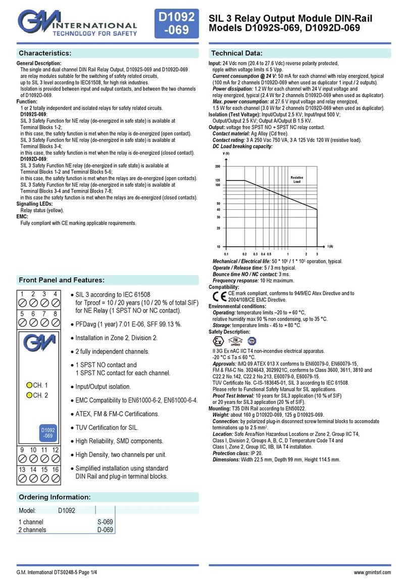
NK TECHNOLOGIES ATS Series User manual

1. Mount the sensor to a suitable surface if required.
2. Run the wire to be monitored through aperture.
3. Connect output wiring.
A. Use 30-12 AWG copper conductors only.
B. Ensure the power supply voltage matches the
model you are installing.
C. Energize the power to the sensor.
4. Adjust Setpoint.
A. LED will display the RMS value of AC current
which will cause the output to change state.
B. Turn the potentiometer until your target current
value is displayed.
5. Analog Signal Output
A. The analog outputs are powered from the sensor
power source.
B. The signal is proportional to the sensor range
selected.
ATS 1- 420 - NOAC - 24U - FL
CASE STYLE:
FL - Solid-Core
OUTPUT:
NOAC - Normally Open solid-state contact,
1 A @ 240 VAC maximum
NCAC - Normally Closed solid-state contact,
1 A @ 240 VAC maximum
SENSOR TYPE:
ATS - AC current operated switch, LED display of the
adjustable trip point.
Model Number KeySpecifi cations
Power Supply 24 VAC/VDC (18-28 V)
Power Consumption 160 mA
Output Operations Isolated solid-state switch and
Analog signal output combination
Output Rating (Switch) 1 A @ 240 VAC maximum (general use)
Response Time <500 ms for 5% over setpoint
(Switch Output) <200 ms for 50% over setpoint
<150 ms for 100% over setpoint
Hysteresis 5%
Setpoint Range ATS1: 1-50 A (adjustable)
ATS2: 4-200 A (adjustable)
Setpoint Adjustment Single turn potentiometer
Setpoint displayed on sensor
Analog Signal 4-20 mA - 500 ohm max impedance
0-5 VDC -5K ohm min impedance
0-10 VDC -5K ohm min impedance
Response Time Average responding
(Analog Output) <250 ms 90% step change
<500 ms 99.5% step change
<2000 ms 100% step change
Accuracy +/-1%, FS
Isolation Voltage Tested to 1480 VAC
Frequency Range 40-100 Hz
Sensing Aperture 0.75” (19.1 mm)
Operating -4 to122°F (-20 to 50°C)
Environmental Surrounding air
0-95% RH, Non-condensing
Pollution Degree 2
Altitude to 6561 ft (2000 meters)
Listings UL/cUL, CE
Quick “How To” Guide
893020010 Rev 3
3511 Charter Park Drive, San Jose, CA 95136
Phone: 800-959-4014 or 408-871-7510
Fax: 408-871-7515
[email protected], www.nktechnologies.com
Know Your Power
POWER SUPPLY:
24U - 24 VAC/VDC
RANGE:
1 - 0-50 Amps AC (setpoint 1-50 A)
2 - 0-200 Amps AC (setpoint 4-200 A)
ANALOG OUTPUT:
420 - 4 to 20 mA
005 - 0-5 VDC
010 - 0-10 VDC
INSTRUCTIONS
ATS SERIES
AC Current Operated Relay
Single Range with Solid State Output and
Analog Signal
Caution! Risk of danger
Safe operation can only be guaranteed if the
transducer is used for the purpose for which it was
designed and within the limits of the technical speci-
fi cations When this symbol is used, it means you
should consult all documentation to understand the
nature of potential hazards and the action required to
avoid them.
Caution! Risk of electrical shock
When operating the transducer certain parts may
carry hazardous live voltage (e.g. Primary conductor,
power supply). The transducer should not be put into
operation if the installation is not complete.
For products intended for the EU market, the following is ap-
plicable to the CE compliance of the product:
The ATS Series may comply with EN 61010-1 CAT III 300 V
max line-to-neutral measurement category. If insulated cable is
used for the primary circuit, the voltage rating of the measure-
ment category can be improved according to the characteristics
given by the cable manufacturer.
Use twisted pair for all connections.
24 Volt AC or DC Power Supply
Fuse at 5 amps maximum
Overvoltage Category I

ATS Series are externally powered, current-operated switches with
0-50 A or 0-200 A analog signal. The contact trips when sensed cur-
rent level exceeds the adjusted setpoint. The normally open contact
closes on current rise, the normally closed contact opens on current
rise. The output resets when current falls 5% below the set point.
The contact alarm point can be used by itself, or the analog signal
can be used alone or both can be used together. There is no need to
short the analog output if it is not used.
ATS sensors can be located in the same environment as motors,
contactors, heaters, pull-boxes, and other electrical enclosures. The
sensor can be installed in any position using the screw holes in the
mounting tabs, or hung directly on wires using a wire tie. Ensure at
least one inch clearance exists between sensor and other magnetic
devices.
Run wire to be monitored through aperture (opening) in the sen-
sor. The direction that the wire passes through the opening is not
important.
Connect the output contact to the load to be switched, being sure
that the load does not exceed the capacity of the output contact. The
contact is solid-state, and will be able to control any AC circuit from
2 to 240 VAC, and up to one amp at any voltage.
Connect the power supply voltage to the appropriate terminals, being
sure that the supplied power matches the sensor designed voltage.
Energize the sensor power supply.
Initially the LED display will show the range maximum.
Set the desired trip point by turning the potentiometer counter-
clockwise. The display will show the amount of AC current needed
to trip the output.
A normally open contact will close at this setpoint, and a normally
closed contact will open.
If used, connect a panel meter or controller input module to the analog
output terminals of the ATS sensor. The sensor output will produce a
signal proportional to the AC current fl owing in the monitored circuit.
The ATS1-420-NOAC-24U-FL will give an output signal of 4mA
with the monitored circuit off , rising to 20 mA at 50 amps.
The ATS2-420-NOAC-24U-FL will give an output of 4 mA with the
monitored circuit off , rising to 20 mA at 200 amps.
Installation Output Wiring
ATS Series setpoint is adjusted using a a single turn poten-
tiometer. The LED three digit display will show the amount
of current needed to cause the output to change state. The
setpoint adjustment can be done before the monitored load
is energized, improving the safety of the installation. The
sensor must be powered to operate the display.
The adjustment is made by turning the screw clockwise to
raise the setpoint, counter clockwise to decrease the setpoint.
The ATS1 models can be set to trip at any current level
from one to 50 amps. The ATS2 or models can be set to trip
between four and 200 amps.
1. Sensor is always tripped
A. The setpoint may be too low. Turn the potentiometer
CW to a higher setting.
B. Switch has been overloaded and contacts are burned
out. Check the output load, remembering to include
inrush on inductive loads (coils, motors, ballasts).
2. Sensor will not trip
A. The setpoint may be too high. Turn the potentiometer
CCW to a lower value.
B. Monitored current is below minimum required. This
sensor can be set to trip at a minimum of 1 amp (ATS1)
or 4 amps (ATS2). Loop the conductor through the
sensing window twice to reduce the trip point to 0.5
(or 2) amps.
C. Switch has been overloaded and “contacts” are burned
out. Check the output load, remembering to include
inrush on inductive loads (coils, motors, ballasts).
D. Current is DC or of a lower frequency than 40 hertz
The sensor can be used to monitor 40-100 hertz AC
current only.
3. Sensor analog signal stays at 4mA (zero voltage)
A. The connection to the load (panel meter, PLC etc.) may
be reversed. Try reversing polarity.
B. The monitored load is not on. Check to be sure there
is voltage at the load terminals.
C. The monitored load is DC or the frequency is below
40 hertz. The ATS can only be used to monitor AC
current.
D. There is more than one phase through the aperture.
Thread only one current carrying conductor through
the aperture, or multiple conductors connected to the
same phase. Do not pass the grounding wire through
the sensor. The neutral can be monitored if the load is
single phase, but do not install both hot and neutral.
Trouble Shooting
Setpoint Adjustment
Connect control or monitoring wires to the sensor. Use
30-12 AWG copper wire rated 75/90°C, and tighten termi-
nals to 5-7 inch-pounds torque. Be sure the output load
does not exceed the switch rating.
CAUTION Incandescent lamps can have “Cold Filament
Inrush” current of up to 10 times their rated amperage. Use
caution when switching lamps with solid-state “contacts”.
Analog Signal
The analog output is proportional to the full range of the
sensor, either 0-50 or 0-200 amps AC. This signal is powered
from the sensor power and no other external (loop) power
is needed. Once the sensor is powered with no primary AC
current through the sensing window, the output will read 4
mA (or 0 VDC). The output signal will rise as the current
increases, up to 20 mA (or 5 VDC or 10 VDC). The ATS1
will produce this signal at 50 amps, and the ATS2 will pro-
duce the signal at 200 amps.
The zero and span calibration is done at the factory, and there
is no need to make any adjustments in the fi eld.
The analog signal is RMS responding, with accuracy of
+/-1% of scale when the current wave shape is sinusoidal.
893020010 Rev 3
The ATS series current relays are externally powered
AC current sensors which utilize a revolutionary meth-
od to set the point where the primary current actuates
the solid-state output. By turning a potentiometer, the
set point will be changed. An LED display on the top of
the sensor shows the value in amps where the contact
will change.
In addition, the ATS sensor produces an analog signal
(choice of 4-20 mA, 0-5 or 0-10 VDC) to be used as an
input to a PLC, panel meter, data acquisition system
or similar. Models with output ranges of 0-50 or 0-200
amps can be selected.
Description
This manual suits for next models
1
Popular Relay manuals by other brands

IFM Electronic
IFM Electronic G1501S Original operating instructions

Emerson
Emerson White-Rodgers 829A-832 installation instructions

Eaton
Eaton ESR5-NV3-30 manual
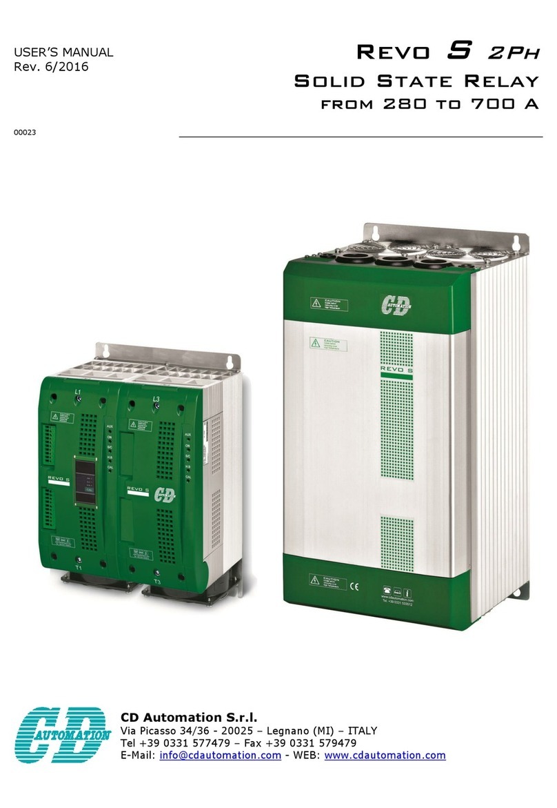
CD Automation
CD Automation Revo S user manual
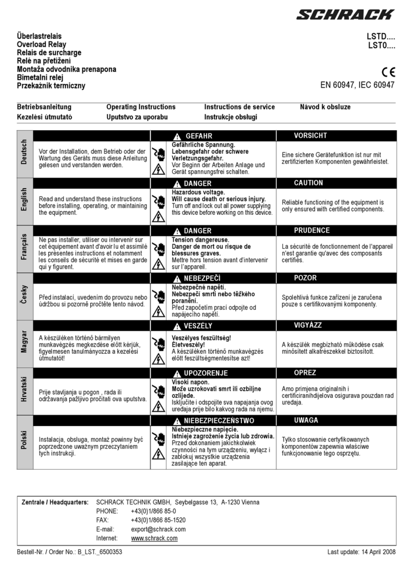
Schrack
Schrack LSTD Series operating instructions

Mitsubishi Electric
Mitsubishi Electric CBV2-A01D1 instruction manual

