manuals.online logo
Brands
  1. Home
  2. •
  3. Brands
  4. •
  5. Contrel
  6. •
  7. Relay
  8. •
  9. Contrel ELRC-B User manual

Contrel ELRC-B User manual

Relè differenziale di terra elettronico con
riduttore toroidale incorporato per montaggio
su profilato DIN
Earth Leakage Relay with internal current
transformer for DIN rail mounting
Il relè ELRC-B è un dispositivo differenziale che, pur
mantenendo l' ampiezza della taratura in corrente e tempo dei
relè della serie ELR, è inserito in un contenitore modulare DIN
da 6 moduli (modulo base 17,5 mm), unitamente al riduttore
toroidale avente un diametro utile di passaggio cavi di 28 mm.
Tutto questo permette di ridurre al minimo il cablaggio, gli
ingombri e di annullare totalmente i disturbi dovuti a campi
elettromagnetici che normalmente si accoppiano sui fili di
collegamento tra toroide e differenziale.
Il relè ELRC-B è inoltre dotato di un microinterruttore che
permette la selezione del funzionamento del relè finale
normalmente diseccitato a riposo (condizione di non
intervento) o normalmente eccitato (sicurezza positiva o fail
safe).
Come per tutta la gamma dei relè ELR questo modello
incorpora degli opportuni filtri sui circuiti di ingresso
rendendolo praticamente immune dai disturbi esterni ed un'
elettronica di controllo dell' efficienza dei circuiti interni e del
riduttore toroidale.
Sul fronte sono programmabili la corrente di intervento (0,025
÷ 25 A), il tempo di intervento (0 ÷ 5 sec.) ed la modalità di
funzionamento del reset (automatico o manuale).
Il dispositivo è inoltre dotato di due contatti in scambio in uscita
e una apposita calotta trasparente di protezione frontale
sigillabile.
Sono disponibili due modelli che si differenziano in base
all’alimentazione ausiliaria :
- ELRC-B 110-230-400V 50-60 Hz 110 Vcc
- ELRC-B 24-48V 50-60 Hz 24-48 Vcc
The Earth Leakage Relay ELRC-B is a device which keeps a wide
possibility of regulation both for time and current.
The housing of ELRC-B is DIN a six module (one module is
17.5mm) together with the internal CT with a diameter of 28mm.
This technique allows to optimize the size of the ELR and reduce
the electromagnetic fields which normally are due when CT and
ELR needs to be wired to each other.
ELRC-B has a micro switch which allows to select output relay
normally not energized or normally energized (positive security or
fail safe).
As all the family range of ELR, this one has implemented several
filters on the input section, making this type of ELR insensible to
external disturbances with a self diagnostic check of the internal
circuits.
On the front panel it is possible to program the trip current (0.025 ÷
25A), trip time (0 ÷ 5 sec.)and the automatic reset modality.
The device is also equipped with two changeover trip contacts and
a plastic cover with possibility to seal it.
Depending on the power supply are available two models :
- ELRC-B 110-230-400V 50-60 Hz 110 Vdc
- ELRC-B 24-48V 50-60 Hz 24-48 Vdc
Manuale istruzioni / user manual. IM 201-IU
Tensione di alim entazion e ausilia ria
Power supply voltage
1) 110 – 230 – 400V 50-60Hz - 110Vcc\dc
2) 24 – 48V 50-60Hz - 24 – 48V cc\dc
Consumo max
Max consumption 3VA
Campo di taratura corrente di intervento  n
Trip current adjustement  n
0,025 ÷ 0,25 A per K = 0,1
0,25 ÷ 2,5 A per K = 1
2,5 ÷ 25 A per K = 10
Campo di taratura tempo di ritardo t
Delay time adjustement t
0,02 ÷ 0,5 sec. per K =1
0,2÷5sec. perK=10
Diametro utile riduttore toriodale incorporato
Internal diamater toroidal current transformer 28 mm
Uscite relè contatti liberi da tensione
Output contacts
2 contatti in scambio 5 A 250V carico resistivo
2 change over contacts 5 A 250 V resistive load
Temperatura di funzionamento
Operating temperature -10 ÷ 60°C
Temperatura di magazzinaggio
Storage temperature -20 ÷ 80°C
U m id ità rela tiva
Relative humidity 90 %
Prova di isolamento
Insulation te st 2,5kV 60sec.
Norme di riferimanto
References standard CEI 41-1 IEC 255 VDE 0664
C o m pa tib ilità e lettro m a gn etica
E lectrom agn etic com p atibility CEI-EN 50081-1 CEI-EN 50082-2
Posizione di montaggio
A sse m b ly p o sitio n
Indifferente
Any
Tipo di collegamento
Type of connection
Tramite morsettiera sezione cavo max 2,5 mmq
By terminal cable section max 2,5 mmq
Grado di protezione
Protection class
IP 40 frontale con calotta chiusa - IP 20 contenitore
IP40 front with cover - IP20 case
Montaggio secondo DIN 50022
Mounting according to DIN 50022
Attacco rapido su profilato da 35 mm
Snap-onfixingonsupportingbar35mm
Caratteristiche tecniche / Technical characteristics
TEST
RESET RESET
I(A)Dt (sec)
ON TRIP
AM
tx10 tx1
NF.S .
IDx1
x10 x0,1 ID
Earth Leakage Relay
ELRC-B
contrel
0,25 0,02
0,5 0,1
10,2
1,5 0,3
20,4
2,5 0,5
1
2
3
4
5
67
Foro passaggio conduttori
della linea da proteggere
hole for passage protected
line cables
Legenda:
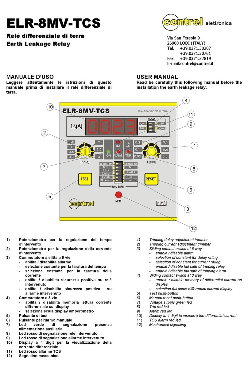
1) potenziomentro di regolazione corrente di intervento
2) potenziomentro di regolazione tempo ritardo di intervento
3) microinterruttori di programmazione:
- a. In posizione 1 riarmo automatico,
in posizione 0 riarmo manuale
- b. Scelta costante taratura costante di moltiplicazione
tempo intervento
in posizione 1 K=10 in posizione 0 K=1
- c,d scelta costante di moltiplicazione corrente di intervento
con c,d in posizione 0 K=0,1
con c in posizione 1, d in posizione 0 K=1
con c,d in posizione 1 K=10
- e in posizione 1 i relè di uscita saranno diseccitati a riposo
in posizione 0 i relè di uscita saranno eccitati a riposo
(sicurezza positiva)
4) pulsante di prova
5) pulsante per il riarmo manuale
6) LED verde di segnalazione presenza alimentazione ausiliaria
7) LED rosso di segnalazione relè intervenuto
8) morsetti di uscita relè finali
9) morsetti per alimentazione ausiliaria
8
9
RESET
AM
tx10 tx1
NF.S.
IDx1
x10 x0,1 ID
a
b
c
d
e
10
Legend:
1) tripping current adjustement potentiometer
2) delay adjustement potentiometer
3) dip switch for setup:
- a. in position 1 automatic reset
in position 0 manual reset
- b. selection of constant for delay rating
in position 1 K=10 in position 0 K= 1
- c. selection of constant for current rating
for c,d in position 0 K=0,1
for c in position 1, d in position 0 K=1
for c,d in position 1 K=10
- e. in position 1 output relays normally not energized
in position 0 output relays normally energized (fail-safe)
4) test push-button
5) manual reset push-button
6) signalling green LED of auxiliary voltage supply
7) signalling red LED of tripped relay
8) output relays terminals
9) auxiliary voltage supply terminals
Man. IM 201-IU
Descrizione - programmazione / Description - setting
elettronica s.r.l.
26900 LODI ( Italy)-ViaS.Fereolo, 9 - Tel. ( 0371 ) 30207-30761-35386
Telefax ( 0371 ) 32819 - E-mail: [email protected]
123456789
11 12 13 14 15 16 17 18
10
UTENZA
LOAD
UTENZA
LOAD
N L1 L2 L3
ALIMENTAZIONE
SUPPLY
ALIMENTAZIONE
SUPPLY
Ba
Aux
Schema di inserzione con interruttore
con bobina di apertura a lancio di
corrente e relè finali in eccitazione (N)
per l’ utilizzo in diseccitazione (F.S.)
collegare alla BA i morsetti 10 - 11
(contatto NA in condizione di NON
intervento)
Connecting diagram with breaker
with opening coil and output relay
NO FAIL SAFE (N)
for use output relay FAIL SAFE (F.S.)
connected to BA terminals 10 - 11
(contact N.O. in NO trip condition)
Terra
Earth
*
* alimentazione ausiliaria Uaux
* power
- morsetti \ 5-1= 380-415 V ac
- morsetti \ 5-3= 220-240V ac
- morsetti \ 5-4= 110-125V ac / dc
- morsetti \ 5-4= 24Vac/dc
- morsetti \ 5-3= 48Vac/dc
supply Uaux:
terminals
terminals
terminals
terminals
terminals
Schema di connessione / Connecting diagram
105
90
73
68
28
26
Caratteristiche dimensionali
Overall dimension

Other Contrel Relay manuals

Contrel ELR-3B User manual

Contrel

Contrel ELR-3B User manual

Contrel ELR-3B User manual

Contrel

Contrel ELR-3B User manual

Contrel ELR-7 User manual

Contrel

Contrel ELR-7 User manual

Contrel ELR-52AS User manual

Contrel

Contrel ELR-52AS User manual

Contrel ELR-4 User manual

Contrel

Contrel ELR-4 User manual

Contrel ELR-1D User manual

Contrel

Contrel ELR-1D User manual

Contrel ELR-3A Series User manual

Contrel

Contrel ELR-3A Series User manual

Contrel ELR-4C User manual

Contrel

Contrel ELR-4C User manual

Contrel ELR-8MV-TCS User manual

Contrel

Contrel ELR-8MV-TCS User manual

Contrel ELR-51AS User manual

Contrel

Contrel ELR-51AS User manual

Contrel ELR-D2-V User manual

Contrel

Contrel ELR-D2-V User manual

Popular Relay manuals by other brands

Siemens siprotec 7SD5 user manual

Siemens

Siemens siprotec 7SD5 user manual

Pilz PNOZ c2 operating manual

Pilz

Pilz PNOZ c2 operating manual

Areva MiCOM P921 Technical guide

Areva

Areva MiCOM P921 Technical guide

Eltako MFZ12DBT-UC manual

Eltako

Eltako MFZ12DBT-UC manual

Mastervolt Multipurpose Contact Output User and installation manual

Mastervolt

Mastervolt Multipurpose Contact Output User and installation manual

Pilz PMUT X1P operating manual

Pilz

Pilz PMUT X1P operating manual

Siemens SIRIUS 3RF22 Series operating instructions

Siemens

Siemens SIRIUS 3RF22 Series operating instructions

ABB TRB Series Instruction leaflet

ABB

ABB TRB Series Instruction leaflet

Pilz PNOZ X2 operating instructions

Pilz

Pilz PNOZ X2 operating instructions

Eaton ETR4-70B-AB Instruction leaflet

Eaton

Eaton ETR4-70B-AB Instruction leaflet

Nibe HR 10 Installer manual

Nibe

Nibe HR 10 Installer manual

Woodward ESDR 4T manual

Woodward

Woodward ESDR 4T manual

LOVATO ELECTRIC PMV55 quick start guide

LOVATO ELECTRIC

LOVATO ELECTRIC PMV55 quick start guide

Hitachi PN-150BE manual

Hitachi

Hitachi PN-150BE manual

Advanced Mxp-007 manual

Advanced

Advanced Mxp-007 manual

urmet domus 788/54 manual

urmet domus

urmet domus 788/54 manual

Zamel exta PB Series instruction manual

Zamel

Zamel exta PB Series instruction manual

Siemens 7SG12 DAD-N manual

Siemens

Siemens 7SG12 DAD-N manual

manuals.online logo
manuals.online logoBrands
  • About & Mission
  • Contact us
  • Privacy Policy
  • Terms and Conditions

Copyright 2025 Manuals.Online. All Rights Reserved.